
Subscribe to Our Youtube Channel
Related Manuals for QCT QuantaGrid Series

Summary of Contents for QCT QuantaGrid Series
- Page 1 QuantaGrid Series D51PH-1ULH Hybrid Scale-Out / High Computing Storage Server Service Guide Version: 1.0...
-
Page 2: Table Of Contents
ABLE OF ONTENTS About the System Introduction..........1-1 Package Contents . - Page 3 Installing the Top Cover........2-11 Fan Module ..........2-13 Removing a Fan Module .
- Page 4 Advanced Screen ........3-5 IntelRCSetup Screen .
- Page 5 Power System ......... . . 4-1 Front Panel User Interface .
- Page 6 Server Component ........4-19 Server identify ........4-20 BIOS POST Code .
- Page 7 Connectors Connectors ..........5-1 Mainboard .
- Page 8 EGULATORY AND OMPLIANCE NFORMATION EVISION ISTORY Revision History Refer to the table below for the updates made to this technical guide. HAPTER PDATES Copyright Copyright © 2015 Quanta Computer Inc. This publication, including all photo- graphs, illustrations and software, is protected under international copyright laws, with all rights reserved.
- Page 9 EGULATORY AND OMPLIANCE NFORMATION EVISION ISTORY About the Book This guide is written for users who want to know the system featuers. For the latest version of this guide, see www.QuantaQCT.com. Intended Application Uses This product was evaluated as Information Technology Equipment (ITE), which may be installed in offices, schools, computer rooms, and similar commercial type loca- tions.
- Page 10 ONVENTIONS Conventions Several different typographic conventions are used throughout this manual. Refer to the following eples for common usage. Bold type face denotes menu items, buttons and application names. Italic type face denotes references to other sections, and the names of the folders, menus, programs, and files.
-
Page 11: Connectors
Structure of this guide Chapter 1: About the System “This section introduces the system, its different configuration(s) and the main features.” Chapter 2: Installing Hardware “This section provides guidance information to properly service components in the system.” Chapter 3: BIOS ... -
Page 12: About The System
About the System Chapter 1 This section introduces the system, its different configuration(s) and the main features. -
Page 13: Introduction
BOUT YOUR YSTEM NTRODUCTION 1.1 Introduction Tailored for hyper scale datacenter and software defined storage, Quanta’s innovative D51PH-1ULH features a hybrid architecture and an ultra-dense hot-swappable 1U plat- form. D51PH-1ULH is a rackmount server based on Intel® Xeon® processor E5-2600 v3 product family and features up to 1TB memory capacity. - Page 14 BOUT YOUR YSTEM NTRODUCTION Specifications Table 1.1: System Specifications PECIFICATIONS ESCRIPTION Form factor 1U rack mount 17.6 x 1.7 x 35.0 inches Dimensions (W x H x D) 448.2 x 43.2 x 890.1 mm Processor type: Intel® Xeon® processor E5-2600 v3 product family Max.
- Page 15 BOUT YOUR YSTEM NTRODUCTION Table 1.1: System Specifications (Continued) PECIFICATIONS ESCRIPTION 1+1 High efficiency redundant hot-plug 700W PSU (default with one PSU only); 100-240Vac, 50-60Hz, 10-5A; Power supply 100-240Vac, 50-60Hz, 10-5A or 240Vdc, 3.5A (for China only); Detailed PSU options please refer to “ordering info”...
-
Page 16: Package Contents
BOUT YOUR YSTEM ACKAGE ONTENTS 1.2 Package Contents (1) the system (1) processor heat sink (1) power supply unit (1) power cord (optional) (1) utility CD (This Guide included) (1) rail kit Note: Note: For exact shipping contents, contact your Quanta sales representative. -
Page 17: A Tour Of The System
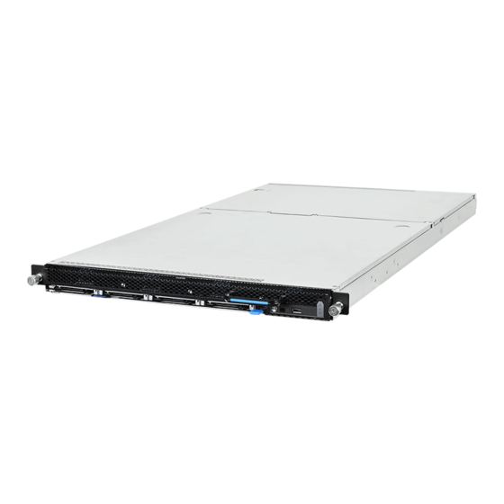
BOUT THE YSTEM OUR OF THE YSTEM 1.3 A Tour of the System System Overview Figure 1-1. System Component Overview... -
Page 18: Mainboard
BOUT THE YSTEM YSTEM VERVIEW Table 1.2: Component Overview ESCRIPTION Support storage drive: 3.5” / 2.5” ; SAS / SATA; hard disk drive (HDD) / Storage drive bay solid state drive (SSD) Storage drive board Connect to storage drive Fans (x6) Fan modules Mainboard Provide all the basic function and information for system operation... -
Page 19: System Front View
BOUT THE YSTEM YSTEM VERVIEW System Front View SSD0 SSD1 SSD2 SSD3 Figure 1-2. System Front View Table 1.3: Front Control Panel View ESCRIPTION Control Panel Control system and status display. Release lever Pull up to release the HDD tray. Hold to pull out the HDD tray from the chassis or push the HDD tray HDD tray handle into the chassis. - Page 20 BOUT THE YSTEM YSTEM VERVIEW Table 1.4: Front Control Panel View (Continued) On, selected unit ID ID LED (Blue) Off, no ID requested USB 2.0 port Connects to USB device Off, Normal Status LED (Amber) On, DC off and critical error Blinking, DC on and critical error.
-
Page 21: System Rear View
BOUT THE YSTEM YSTEM VERVIEW System Rear View Figure 1-4. System Rear View Table 1.5: Rear Panel View ESCRIPTION Redundant Power Supply Unit Expansion slot Supports Quanta mezzanine (PCIe Gen3 x16) System Rear I/O Mainboard (MB) I/O features Rear I/O Figure 1-5. -
Page 22: Psu View
BOUT THE YSTEM YSTEM VERVIEW PSU View Figure 1-6. PSU View Table 1.7: PSU View ESCRIPTION Release latch Press and hold to unlock PSU from chassis bay. AC input power connector Connect power plug. Cable clip Secure the power cord. Handle Hold to remove the PSU from the chassis bay. -
Page 23: Led Definitions
LED D BOUT THE YSTEM EFINITIONS LED Definitions Front SAS/SATA HDD/SSD LED The system features storage drive cage supporting up to 4x 2.5” SAS/SATA HDD/SSD (7mm) on front bottom chassis. Each carrier has one HDD/SSD Present / Fault LED. See the following illustration and table for details. -
Page 24: Bmc Management Port Led
LED D BOUT THE YSTEM EFINITIONS BMC Management Port LED Speed Link / Activity Figure 1-8. Management Port LED Table 1.10: Management Port LED Behavior TATUS PEED CTIVITY Unplug Plug in no access Green: on 1G Link +Active Amber: on Green: blinking 100M Link + Active Green: on... -
Page 25: Installing Hardware
Installing Hardware Chapter 2 This section provides guidance information to properly service components in the sys- tem. -
Page 26: Safety Measures
NSTALLING ARDWARE AFETY EASURES 2.1 Safety Measures WARNING! Always ask for assistance to move or lift the system. WARNING! Only perform troubleshooting as authorized by the product documentation, or as directed by a service and support team. Repairs not authorized by warranty may void the warranty and damage the system. -
Page 27: Power Supply Unit
NSTALLING ARDWARE OWER UPPLY 2.2 Power Supply Unit If your server is configured in a redundant configuration, you can replace a failed or failing power supply without powering down the server. Use the LED on the power supply to determine the status of the target PSU. Each power supply module has a single bi-color LED, see PSU View on page 1-10. -
Page 28: Installing The Power Supply Unit
NSTALLING ARDWARE NSTALLING THE OWER UPPLY Installing the Power Supply Unit CAUTION! NSURE ALL POWER IS DISCONNECTED FROM THE SYSTEM BEFORE PROCEEDING 1. Locate the target power bay. 2. Remove the new power supply from the protective packaging and place it on a clean ESD protected work surface. -
Page 29: Hdd Tray
HDD T NSTALLING ARDWARE 2.3 HDD Tray WARNING! All the service procedures for the HDD tray including hot-plug Hard Disk Drives replacement must be performed within 30 minutes without turning-off system. The HDD tray houses the HDD bay and various other components. All components other than the HDD bay require the full extension of the HDD tray before servicing. -
Page 30: Securing A Hdd Tray
HDD T NSTALLING ARDWARE ECURING A 2. Hold the tray handle and pull the tray out of the chassis smoothly until fully extend. Figure 2-3. Releasing and pulling the HDD Tray out from the chassis Securing a HDD Tray 1. Using the tray handle, gently push the tray into the chassis. Figure 2-4. -
Page 31: Hot-Plug Hdd
NSTALLING ARDWARE PLUG 2.4 Hot-plug HDD WARNING! All the service procedures for the HDD tray including hot-plug Hard Disk Drives replacement must be performed within 30 minutes without turning-off system. WARNING! Repairs should be performed by a certified service technician. Damage to the system or com- ponents due to unauthorized servicing is not covered by the warranty agreement. -
Page 32: Removing A Hdd Carrier And Hdd From The Hdd Tray
NSTALLING ARDWARE EMOVING A CARRIER AND FROM THE TRAY Removing a HDD carrier and HDD from the HDD tray Prerequisite: Prerequisite: Check the HDD Array LED on the front control panel and pull out the HDD tray from the chassis. See “Releasing the HDD Tray” on page 4. Locate the HDD carrier in the HDD array. - Page 33 NSTALLING ARDWARE EMOVING A CARRIER AND FROM THE TRAY 1. Press the release button on HDD carrier handle and pull the handle to open position as shown. Figure 2-7. Removing a HDD carrier from the HDD tray 2. Remove the HDD carrier assembly from the HDD tray on the chassis. 3.
-
Page 34: Installing A Hdd Carrier With Hdd To Hdd Tray
NSTALLING ARDWARE NSTALLING A CARRIER WITH TRAY Installing a HDD carrier with HDD to HDD tray Prerequisite: Prerequisite: Locate the HDD carrier slot on the chassis for servicing. 1. Align the screw holes on the HDD carrier assembly bracket with the wells on the HDD. - Page 35 NSTALLING ARDWARE NSTALLING A CARRIER WITH TRAY 2. Align the HDD carrier assembly with the carrier slot on the HDD tray on the chassis. Place the HDD carrier on the HDD tray on the chassis. Push the handle of HDD car- rier assembly to close position to secure the HDD carrier assembly to the HDD tray as shown.
-
Page 36: Top Cover
NSTALLING ARDWARE OVER 2.5 Top Cover Removing the Top Cover The following procedure illustrates the system. CAUTION! NSURE ALL POWER IS DISCONNECTED FROM THE SYSTEM BEFORE PROCEEDING 1. Press the top cover release button (A). 2. Slide the top cover away from the HDDs. (B) Figure 2-11. - Page 37 NSTALLING ARDWARE NSTALLING THE OVER 2. Slide the cover toward the front of the chassis until it lock in place (B). Figure 2-12. Installing the Top Cover 2-12...
-
Page 38: Fan Module
NSTALLING ARDWARE ODULE 2.6 Fan Module The system supports six dual-rotor fan modules on the system. See the following image for fan module identification. Each pair of fans consist of one primary fan and one redundant fan that serves as a backup on the event that the primary fan fails. -
Page 39: Installing A Fan Module
NSTALLING ARDWARE NSTALLING A ODULE 7. Pull the fan module up to remove it. Figure 2-14. Removing a Fan Module Installing a Fan Module CAUTION! OSITION THE FAN MODULE CORRECTLY TO AVOID SEVERE SYSTEM OVERHEATING 1. Locate the slot for the fan module. 2. - Page 40 NSTALLING ARDWARE NSTALLING A ODULE 3. Install the fan module and seat in the chassis. Figure 2-15. Installing a Fan Module 4. Guide the cable through the corresponding opening. 5. Replace the air duct. 6. Replace the chassis top cover. 7.
-
Page 41: Memory Modules
NSTALLING ARDWARE EMORY ODULES 2.7 Memory Modules WARNING! Mainboard is supplied with all DIMM slots populated with dummy DIMMs for proper air flow. When installing and replacing memory modules, only remove those dummy DIMMs that are to be directly replaced. All DIMM slots must be occupied at all times by either a memory mod- ule or dummy DIMM. -
Page 42: Installing A Memory Module
NSTALLING ARDWARE NSTALLING A EMORY ODULE WARNING! Memory modules remain hot after the system is powered down. Allow sufficient time for the memory modules to cool before handling system components. 2. Press down on the two memory module slot levers (A). The memory module par- tially ejects. - Page 43 NSTALLING ARDWARE NSTALLING A EMORY ODULE Push the memory module firmly into the memory module slot. The locking latches should automatically close over the edges of the memory board when fully inserted into the slot. Figure 2-17. Installing Memory Module 2-18...
-
Page 44: Processor Heat Sink
NSTALLING ARDWARE ROCESSOR 2.8 Processor Heat Sink Note: All the instructions and images in this section are for illustration purposes only and may not reflect the actual product. Removing a Processor Heat Sink 1. Remove the top cover. WARNING! The heatsink remains hot after the system has been powered down. Allow sufficient time to cool before handling system components. - Page 45 NSTALLING ARDWARE NSTALLING A ROCESSOR 3. Install the heat sink. Make sure the screw(s) are inserted into the screw wells. Figure 2-19. Removing the Heat Sink 4. Tighten the screw(s) in the order shown. 5. Repeat steps for the remaining heat sink. 6.
-
Page 46: Processor
NSTALLING ARDWARE ROCESSOR 2.9 Processor Note: All the instructions and images in this section are for illustration purposes only and may not reflect the actual product. CAUTION! NSURE ALL POWER IS DISCONNECTED FROM THE SYSTEM BEFORE PROCEEDING WARNING! The processor remains hot after the system has been powered down. Allow sufficient time to cool before handling system components. -
Page 47: Installing The Processor
NSTALLING ARDWARE NSTALLING THE ROCESSOR 6. Lift the load plate upright. Figure 2-22. Lifting Processor Load Plate 7. Remove the processor. Figure 2-23. Removing the processor 8. To remove the second processor, repeat the previous steps. CAUTION! VOID CONTACT WITH ANY THERMAL GREASE ON THE PROCESSOR Installing the Processor 1. - Page 48 NSTALLING ARDWARE NSTALLING THE ROCESSOR 6. Align the triangle identifying pin 1 of the processor with the triangular cutout on the socket. 7. Locate the pin1 (A) on processor and the pin1 (B) corner of the socket. 8. Locate the indents (C) on processor and corresponding tab (D) on socket. 9.
-
Page 49: Expansion Card
NSTALLING ARDWARE XPANSION 2.10 Expansion Card CAUTION! NSURE ALL POWER IS DISCONNECTED FROM THE SYSTEM BEFORE PROCEEDING The system supports the riser assembly configuration. It is designed for the installation of a mezzanine card (linking board). Removing a Riser Assembly To remove a riser assembly for the installation of a mezzanine card, follow these guide- lines: 1. -
Page 50: Installing A Riser Assembly
NSTALLING ARDWARE NSTALLING A ISER SSEMBLY Installing a Riser Assembly 1. Install the assembly on the chassis and press down firmly to connect it to the main- board (A). 2. Twist the securing plug (B) and then release to secure the assembly in place. Figure 2-27. -
Page 51: Ocp Mezzanine Board
OCP M NSTALLING ARDWARE EZZANINE OARD 2.11 OCP Mezzanine Board CAUTION! NSURE ALL POWER IS DISCONNECTED FROM THE SYSTEM BEFORE PROCEEDING Removing a OCP Mezzanine Board 1. Remove the system from the rack to power it down. 2. Remove the top cover. See Removing the Top Cover on page 2-11. 3. -
Page 52: Installing An Ocp Mezzanine Board
OCP M NSTALLING AN EZZANINE OARD NSTALLING ARDWARE 5. Remove the bracket from the chassis. Figure 2-29. Removing the Bracket 6. Place the OCP mezzanine board in an anti-static bag. 7. Replace the OCP mezzanine board. 8. Install the top cover. See Installing the Top Cover on page 2-11. 9. - Page 53 OCP M NSTALLING ARDWARE NSTALLING AN EZZANINE OARD 3. Remove the filler from the bracket. Figure 2-30. Removing the Bracket 4. Install the suitable bracket to chassis. 2-28...
- Page 54 OCP M NSTALLING AN EZZANINE OARD NSTALLING ARDWARE 5. Align the OCP assembly to the standoffs and secure with screws. Figure 2-31. Installing the Bracket 2-29...
- Page 55 OCP M NSTALLING ARDWARE NSTALLING AN EZZANINE OARD 6. Secure the OCP assembly to the chassis with screws. Figure 2-32. Installing the OCP Mezzanine Board 7. Install the top cover. See Installing the Top Cover on page 2-11. 8. Replace the system in the rack to power on. 2-30...
- Page 56 OCP M NSTALLING AN EZZANINE OARD NSTALLING ARDWARE 2-31...
-
Page 57: Bios
BIOS Chapter 3 This section provides information regarding the BIOS architecture, BIOS update utility, server management, checkpoints, and error handling found in the system. -
Page 58: Bios Setup Utility
BIOS BIOS S ETUP TILITY 3.1 BIOS Setup Utility The BIOS Setup utility is provided to perform system configuration changes and to display current settings and environment information. The BIOS Setup utility stores configuration settings in system non-volatile storage. Changes affected by BIOS Setup will not take effect until the system is rebooted. The BIOS Setup Utility can be accessed during POST by using the <DEL>... -
Page 59: Keyboard Commands
BIOS EYBOARD OMMANDS When Quiet Boot is disabled, the message “press <DEL> or <F2> to enter setup” will be displayed on the diagnostics screen. Keyboard Commands The bottom right portion of the Setup screen provides a list of commands that are used to navigate through the Setup utility. -
Page 60: Menu Selection Bar
BIOS ELECTION Table 2: Keyboard Commands (Continued) PTION ESCRIPTION The minus key on the keypad is used to change the value of the cur- Change Value rent item to the previous value. This key scrolls through the values in the associated pick list without displaying the full list. The plus key on the keypad is used to change the value of the current menu item to the next value. -
Page 61: Server Platform Setup Utility Screens
BIOS ERVER LATFORM ETUP TILITY CREENS Server Platform Setup Utility Screens The sections below describe the screens available for the configuration of a server plat- form. In these sections, tables are used to describe the contents of each screen. These tables follow the following guidelines: The text and values in the Setup Item, Options, and Help columns in the tables are ... -
Page 62: Advanced Screen
BIOS DVANCED CREEN Table 3: Main Screen Description ETUP PTIONS OMMENTS Information only. Displays the BIOS Vendor BIOS Vendor. Information only. Displays the Core Version AMI BIOS Core version. Information only. Displays the Compliancy BIOS compliancy. Information only. Displays the Project Version Project version. - Page 63 BIOS DVANCED CREEN To access this screen from the Main screen, press the right arrow until the Advanced screen is chosen. Figure 3-2. Advanced Screen Table 4: Advanced Screen Description ETUP PTIONS OMMENTS System Super IO Chip Parame- Super IO Configuration ters.
-
Page 64: Intelrcsetup Screen
BIOS DVANCED CREEN IntelRCSetup Screen The IntelRCSetup screen provides an access point to configure several options. On this screen, you can select the option that is to be configured. Configurations are performed on the selected screen, not directly on the IntelRCSetup screen. To access this screen from the Main screen, press the right arrow until the IntelRCSetup screen is chosen. -
Page 65: Server Management Screen
BIOS ERVER ANAGEMENT CREEN Table 5: IntelRCSetup Screen Description (Continued) ETUP PTIONS OMMENTS Memory Config- Displays and provides option to uration change the Memory Settings IIO Configura- Displays and provides option to tion change the IIO Settings PCH Configura- Displays and provides option to tion change the PCH Settings Server ME Con-... - Page 66 BIOS ERVER ANAGEMENT CREEN Table 6: Server Management Screen Description (Continued) ETUP PTIONS OMMENTS BMC firmware Information only. Displays the version BMC firmware version. Information only. Displays the IPMI version IPMI version. [Disabled] Enable or Disable FRB-2 timer Not available if FRB2 Timer is dis- FRB-2 Timer (POST timer) abled.
-
Page 67: Boot Options Screen
BIOS PTIONS CREEN Boot Options Screen The Boot Options screen displays any bootable media encountered during POST, and allows the user to configure desired boot device. If no boot devices are available – for example, both onboard LAN are disabled and no bootable device connected when Boot Mode is set to Legacy –... -
Page 68: Security Screen
BIOS ECURITY CREEN Table 7: Boot Options Screen Description (Continued) ETUP PTIONS OMMENTS This item decides what devices (Legacy or UEFI) BIOS should try [LEGACY] Boot mode Select boot mode LEGACY/UEFI to boot when let the system auto select [UEFI] boot up without manually select boot device. -
Page 69: Exit Screen
BIOS CREEN To access this screen from the Main screen, select the Security option. Figure 3-6. Security Screen Table 8: BIOS Screen Description ETUP PTIONS OMMENTS Administrator Set Administrator Password Password User Password Set User Password Secure Boot Customizable Secure Boot set- menu tings Exit Screen... - Page 70 BIOS CREEN the user saved earlier, instead of being restored to the factory defaults. For boot devices, BIOS only supports at most six USB boot devices. Figure 3-7. Exit Screen Table 9: Exit Screen Description ETUP PTIONS OMMENTS Discard Changes and Exit system setup without Exit saving any changes.
-
Page 71: Loading Bios Defaults
BIOS BIOS D OADING EFAULTS Loading BIOS Defaults Different mechanisms exist for resetting the system configuration to the default values. When a request to reset the system configuration is detected, the BIOS loads the default system configuration values during the next POST. The request to reset the system to the defaults can be sent in the following ways: A request to reset the system configuration can be generated by pressing <F9>... -
Page 72: Bios Update Utility
BIOS BIOS U PDATE TILITY 3.2 BIOS Update Utility The flash ROM contains system initialization routines, the BIOS Setup Utility, and runtime support routines. The exact layout is subject to change, as determined by BIOS. The flash ROM also contains initialization code in compressed form for onboard peripherals, like SCSI, NIC and video controllers. -
Page 73: Bios Setting Utility
BIOS CMOS LEAR Memory reference code. Microcode updates. ME Firmware. BIOS Setting Utility Use AMISCE to import/export BIOS setting in Linux: 1. Export BIOS setting and generate script file: /o /s NVRAM.txt 2. Import BIOS setting with script file: /i /s NVRAM.txt BIOS Revision The BIOS revision is used to identify the BIOS image and BIOS phase. -
Page 74: Bios Update Via Bmc Instructions (Optional)
BIOS BIOS U BMC I PDATE NSTRUCTIONS PTIONAL BIOS Update Via BMC Instructions (Optional) In order to prevent BIOS corruption during upgrade process due to power failure or unex- pected interrupt, “BIOS update via BMC instructions” provides a safe mechanism which allow server manager to rebuild server BIOS through BMC. -
Page 75: Server Management
BIOS ERVER ANAGEMENT 3.3 Server Management The BIOS supports many standard-based server management features and several propri- etary features. The Intelligent Platform Management Interface (IPMI) is an industry stan- dard and defines standardized, abstracted interfaces to platform management hardware. The BIOS implements many proprietary features that are allowed by the IPMI specification, but these features are outside the scope of the IPMI specification. -
Page 76: Reset
BIOS ONSOLE EDIRECTION Table 10: Keystroke Mappings (Continued) ANSI E SCAPE EQUENCE INDOWS LATFORM ESIGN <ESC>8 <ESC>9 <ESC>0 <ESC>! <ESC>@ Home <ESC>[<Shift>h <ESC>h <ESC>[<Shift>k <ESC>k <ESC>+ <ESC>- Page Up <ESC>? Page Down <ESC>/ Reset <ESC>R<ESC>r<ESC>R Standalone <Esc> Key for Headless Operation The Microsoft Headless Design Guidelines describes a specific implementation for the <Esc>... -
Page 77: Interface To Server Management (Optional)
BIOS BIOS S ETWORK UPPORT Interface to Server Management (Optional) If the BIOS determines that console redirection is enabled, it will read the current baud rate and pass this value to the appropriate management controller via the Intelligent Plat- form Management Bus (IPMB). Network BIOS Support PXE Boot The BIOS supports the EFI PXE implementation. - Page 78 BIOS HECKPOINTS b. Error code (POST Error/ MRC Fatal/Warning Code One reset switch (To trigger system reset) 3-21...
-
Page 79: Bmc
Chapter 4 This section provides information and key features of BMC (Baseboard Management Controller). -
Page 80: Server Management Software
ERVER ANAGEMENT OFTWARE 4.1 Server Management Software Server System Overview In a server system, BMC is an independent system of the host server system. This indepen- dent system has its own processor and memory; the host system can be managed by the BMC system even if the host hardware or OS hangs or is unable to function. -
Page 81: Front Panel User Interface
RONT ANEL NTERFACE Front Panel User Interface The BMC provides control panel interface functionality including indicators (Fault/status and Identify LEDs) and buttons (Power/ID). Power Button The Power buttons allow to control the system status. ID Button The control panel Chassis Identify button toggles the state of the Chassis ID LED. If the ID LED is off, then a button press will turn the LED on (blinking). -
Page 82: Session And User
ERIAL Obtain Field Replaceable Unit (FRU) information Obtain System Event Log (SEL) entries Obtain Sensor Data Records (SDR) Set Platform Event Filtering (PEF) Set LAN configurations In addition, the BMC supports LAN alerting in the form of SNMP traps that conform to the IPMI Platform Event Trap (PET) format. -
Page 83: Bmc Firmware Update
BMC F IRMWARE PDATE The action support Power off, Power Reset, Power Cycle and NMI. All Platform Event Filter Table is default disabled. PEF Startup Delay and Last Processed Event tracking is not supported. PEF table lookup isn’t correlated to log SEL to SEL Repository. ... -
Page 84: Bmc Recovery
BMC R ECOVERY 4.2 BMC Recovery This section provides guidelines on BMC recovery process in DOS and Linux systems. Recovery Process in DOS System To recover BMC on a DOS system, do as follows: 1. Copy BMC firmware package to your USB key. 2. -
Page 85: Smash
SMASH 4.3 SMASH Quanta SMASH is a tool that allows you to use Secure Shell (SSH) to login in the embedded Linux of BMC from remote terminal and gather information as well as give you control over things like power resets, power off. The basic structure is shown as below: Figure 4-1. -
Page 86: System Level Commands
SMASH Input command in Linux: ssh sysadmin@<Server IP> Figure 4-2. SMASH Activity Diagram Here provides you the commands about system level and BMC level. System Level Commands The system level commands provide you the information and power state control. Table 4.2: Targets and Verbs UPPORTED ERBS ELATED... - Page 87 SMASH Power-on system start /SYS Power-off system stop /SYS Power-reset system reset /SYS Display all system voltage show /SYS/voltage Display all system fan show /SYS/fan Display all system temperature show /SYS/temperature Display all system power supply show /SYS/powerSupply /SYS This command provides you the hig-level status of the system chassis and main power subsystem.
- Page 88 SMASH /SYS/voltage This command returns a high level version of the system voltages health status. Table 4.4: /SYS/voltage ROPERTY ALID ALUE CCESS ESCRIPTION indicates the status not available /unknown (typically because system power is off) indicates the monitored parameters within nor- mal operating ranges Sensor name list of vlotage...
- Page 89 SMASH Table 4.6: /SYS/temperature ROPERTY ALID ALUE CCESS ESCRIPTION indicates the status not available /unknown (typically because system power is off) indicates the monitored parameters within nor- mal operating ranges Sensor name list of temperature nonCritical nonCritical critical indicates the hardware outside normal operat- ing range critical indicates the hardware exceeding specified rat-...
-
Page 90: Bmc Information
SMASH A1: The other power supply status is " AllDeasserted ". Q2: My system supports two power supply slots and two power supply units connected. But only one power cord plugged. What is the other power supply status? A2: The other power supply status shows "Presence, PredictiveFail, InputLost(AC/DC) ". BMC Information The BMC level commands provide several options to configure and display parameters of the management agent. - Page 91 SMASH Table 4.9: /SYS/fan (Continued) ROPERTY ALID ALUE CCESS ESCRIPTION ServerIdentify Configuring server identify LED blinking Display the NIC physical address used by server BMCMAC management agent 4-12...
-
Page 92: Web Graphical User Interface (Gui) For Esms
(GUI) ESMS RAPHICAL NTERFACE 4.4 Web Graphical User Interface (GUI) for ESMS Using the Web GUI The BMC firmware features an embedded web server enabling users to connect to the BMC using a Web browser (e.g. Microsoft Internet Explorer). The Web GUI shows system information, system events, system status of managed servers, and other system-related information. -
Page 93: Dashboard
ASHBOARD Table 5: Default Username and Password IELD EFAULT Username admin Password admin After passing authentication, the following web page appears. Note: The default username and password are in lowercase characters. It is advised to change the admin password once you have logged in. Click the Help button on the right corner of the page for assistance, the Refresh button to refresh the page, or the Logout button to exit. -
Page 94: Device Information
ASHBOARD To open the Dashboard page, click Dashboard from the main menu. A sample screenshot of the Dashboard page is as follows: Figure 4-5. Dashboard A brief description of the Dashboard page is given in the next section. Device Information The Device Information displays the following information: Table 7: Device Information Page ESCRIPTION... -
Page 95: Network Information
ERVER NFORMATION Network Information The Network Information of the device with the following fields is shown in the following table. To edit the network Information, click Edit. Table 8: Network Information ESCRIPTION Host Name Read only field showing the DNS Hostname of the device. MAC Address Read only field showing the IP address of the device. -
Page 96: Fru Information
FRU I NFORMATION FRU Information Server Component Server Identify BIOS POST Code The following screenshot displays the Server Information menu items: Figure 4-6. Server Information – Menu FRU Information In the MegaRAC GUI, the FRU Information Page displays the BMC FRU file information. The information displayed in this page is Basic Information, Common Header Information, Chassis Information, Board Information and Product Information of the FRU device. - Page 97 FRU I NFORMATION To open the FRU Information Page, click on FRU Information on top menu. Select a FRU Device ID from the Basic Information section to view the details of the selected device. A screenshot of FRU Information page is shown as follows: Figure 4-7.
-
Page 98: Server Component
FRU I NFORMATION Board Manufacturer Board Product Name Board Serial Number Board Part Number FRU File ID Board Extra Product Information Product Information Area Format Version Language Manufacturer Name Product Name ... -
Page 99: Server Identify
FRU I NFORMATION Table 6: Component Information Page (Continued) ESCRIPTION Displays the following information: Memory ID, Status, Socket, Memory Information Module Size, Model, Frequency, and Memory type*. Server identify The Server Identify page displays the indicator LED status. You can select a Server Identify Operation to control the indicator LED. -
Page 100: Bios Post Code
FRU I NFORMATION BIOS POST Code The page displays recent BIOS Port 80h POST code. Figure 4-10. BIOS POST Code Table 8: BIOS POST Code Page ESCRIPTION Current Codes Current BIOS Port 80h POST code Previous Codes Current BIOS Port 80h POST code Server Health Group The Server Health Group consists of the following two items: Sensor Readings... -
Page 101: Sensor Readings
FRU I NFORMATION The Server Health screenshot allows to select Sensor Readings or Event Log as shown in the following image: Figure 4-11. Server Health – Menu Sensor Readings In MegaRAC GUI, the Sensor Readings page displays all the sensor related information. To open the Sensor readings page, click Server Health >... - Page 102 FRU I NFORMATION you want to display in the list. Some examples of other sensors include Temperature Sen- sors, Fan Sensors, and Voltage Sensors etc. Select a particular sensor from the list. On the right hand side of the screen you can view the Thresholds for this sensor.
-
Page 103: Event Log
FRU I NFORMATION View this Event Log View the Event Log page for the selected sensor. Sensor Reading status You can read currently sensor status in this page, each sensor name have its SDR setting data in BMC function SPEC, the status according SDR setting will display as following matrix: Table 9: Sensor Readings status TATUS... - Page 104 FRU I NFORMATION Table 10: Event Log Page ESCRIPTION The category options: All Events, System Event Records, BIOS Gener- ated Events, SMI Handler Events, System Management Software Events, Event Log Category System Software - OEM Events, Remote Console software Events, Termi- nal Mode Remote Console software Events.
-
Page 105: Configuration Group
ONFIGURATION ROUP Configuration Group Configuration Group page allows access to various configuration settings. A screenshot of the Configuration Group menu is shown in the following figure: Figure 4-15. Configuration Group Menu A detailed description of the Configuration menu is given in the following sections. Active Directory An active directory is a directory structure used on Microsoft Windows based computers and servers to store information and data about networks and domains. - Page 106 ONFIGURATION ROUP Table 11: Active Directory Settings Page (Continued) ESCRIPTION The name that identifies the role group in the Active Directory. Note: Role Group ID Role Group Name is a string of 64 alpha-numeric characters. Special symbols (hyphen and underscore) are allowed. This name identifies the role group in Active Directory.
- Page 107 ONFIGURATION ROUP 5. Specify the time (in seconds) to wait for Active Directory queries to complete in the Time Out field. Note: Default Time out value: 120 seconds. Range from 15 to 300 allowed. 6. Configure IP addresses in Domain Controller Server Address1, Domain Control- ler Server Address2 &...
-
Page 108: Dns
ONFIGURATION ROUP 13. Click Add to save the new role group and return to the Role Group List. 14. Click Cancel to cancel the settings and return to the Role Group List. To modify a Role Group 15. In the Advanced Directory Settings Page, select the row that you wish to modify and click Modify Role Group. - Page 109 ONFIGURATION ROUP Table 12: DNS Server Settings Page ESCRIPTION Host configuration Host Settings Choose either Automatic or Manual settings. It displays hostname of the device. If the Host setting is chosen as Man- Host Name ual, then specify the hostname of the device. Register BMC Register BMC To enable/disable Register BMC.
-
Page 110: Ldap/E-Directory
ONFIGURATION ROUP 1. Choose the Host Configuration either Automatic or Manual. Note: If you choose Automatic, you need not enter the Host Name and if you choose Manual, you need to enter the Host Name. 2. Enter the Host Name in the given field if you have chosen Manual Configuration. 3. - Page 111 ONFIGURATION ROUP To open LDAP Settings page, click Configuration > LDAP from the main menu. A sample screenshot of LDAP Settings Page is shown in the screenshot below. Figure 4-20. LDAP Settings Page The fields of LDAP Settings Page are explained below. Table 13: LDAP Settings Page ESCRIPTION To configure LDAP Advanced Settings.
- Page 112 ONFIGURATION ROUP 3. Enter the IP address of LDAP server in the IP Address field. Note: IP Address made of 4 numbers separated by dots as in 'xxx.xxx.xxx.xxx' . Each Number ranges from 0 to 255. First Number must not be 0. ...
-
Page 113: Mouse Mode
ONFIGURATION ROUP Note: Search Base is a string of 255 alpha-numeric characters. Special symbols hyphen, underscore and dot are allowed. 11. In the Role Group Privilege field, enter the level of privilege to assign to this role group. 12. -
Page 114: Network
ONFIGURATION ROUP Table 14: Mouse Mode Settings Page (Continued) ESCRIPTION Save To save any changes made. Reset To Reset the modified changes. Procedure: 1. Choose either of the following as your requirement: Set mode to Absolute Note: Applicable for all Windows versions; RHEL Linux versions not below than RHEL6; Fedora Linux versions not below than FC14. - Page 115 ONFIGURATION ROUP To open Network Settings page, click Configuration > Network from the main menu. A sample screenshot of Network Settings Page is shown in the screenshot below. Figure 4-24. Network Settings Page The fields of Network Settings page are explained below. 4-36...
- Page 116 ONFIGURATION ROUP Table 15: Network Settings Page ESCRIPTION LAN Interface Lists the LAN interfaces. LAN Settings To enable or disable the LAN Settings. This field displays the MAC Address of the device. This is a read only MAC Address field. This option lists the IPv4 configuration settings.
-
Page 117: Pef
ONFIGURATION ROUP Table 16: Reserved IPv6 Address REFIX LLOCATION EFERENCE REFIX LLOCATION EFERENCE 0000::/8 Reserved by IETF [RFC4291] c000::/3 Reserved by IETF [RFC4291] 0100::/8 Reserved by IETF [RFC4291] e000::/4 Reserved by IETF [RFC4291] 0200::/7 Reserved by IETF [RFC4048] f000::/5 Reserved by IETF [RFC4291] 0400::/6 Reserved by IETF... - Page 118 ONFIGURATION ROUP this ratio of pre?]configured entries to run?]time configurable entries can be reallocated if necessary. Figure 4-25. PEF Management – Event Filter The fields of PEF Management – Event Filter Tab are explained below. This page contains the list of configured PEF’s. Table 17: PET Management - Event Filter ESCRIPTION PEF ID...
- Page 119 ONFIGURATION ROUP 2. Select one of PEF ID list and click Modify to modify event Filter entry page. A sample screenshot of modify Event Filter Page is in seen the screenshot below. Figure 4-26. Add Event Filter Entry Page 3. In the Event Filter Configuration section, PEF ID displays the ID for configured PEF entry (read?]only).
- Page 120 ONFIGURATION ROUP Alert Policy Tab This page is used to configure the Alert Policy and LAN destination. You can add, delete or modify an entry in this page. Figure 4-27. PEF Management – Alert Policy The fields of the PEF Management – Alert Policy Tab are explained below. Table 18: PEF Management - Alert Policy ESCRIPTION Displays Policy entry number for the newly configured entry (read-...
- Page 121 ONFIGURATION ROUP Table 18: PEF Management - Alert Policy (Continued) ESCRIPTION To choose a particular destination from the configured destination list. Note: Destination Selector LAN Destination has to be configured - under Configuration -> PEF -> LAN Destination. Modify To modify the existing entries. Delete To delete Alert Policy list.
- Page 122 ONFIGURATION ROUP 10. In the Alert String Key field, choose any one value that is used to look up the Alert String to send for this Alert Policy entry. 11. Click Add to save the new alert policy and return to Alert Policy list. 12.
- Page 123 ONFIGURATION ROUP Table 19: PEF Management - LAN Destination (Continued) ESCRIPTION If Destination type is SNMP Trap, then enter the IP address of the system that will receive the alert. Destination address will support the follow- ing: Destination Address IPv4 address format.
- Page 124 ONFIGURATION ROUP Configuring the SNMP: 1. Navigate to PEF Management. 2. Select LAN Destination tab in Configuration section. 3. Select from LAN Destination menu SNMP Trap. Figure 4-31. Selecting SNMP Trap A Modify LAN Destination entry menu opens. 4. Key in an IP address to the Destination Address field. 5.
-
Page 125: Radius
ONFIGURATION ROUP RADIUS RADIUS is a modular, high performance and feature-rich RADIUS suite including server, cli- ents, development libraries and numerous additional RADIUS related utilities. In MegaRAC GUI, this page is used to set the RADIUS Authentication. To open RADIUS Settings page, click Configuration > RADIUS from the main menu. A sam- ple screenshot of RADIUS Settings Page is shown in the screenshot below. -
Page 126: Remote Session
ONFIGURATION ROUP Table 20: RADIUS Settings Page (Continued) ESCRIPTION Save To save the settings. Reset To reset the modified changes. Procedure: 1. Enable the RADIUS Authentication checkbox to authenticate the RADIUS. 2. Enter the port number in the Port Number field. 3. -
Page 127: Smtp
ONFIGURATION ROUP Table 21: Remote Session Settings Page (Continued) ESCRIPTION Two types of VM attach mode are available: Attach: Immediately attaches Virtual Media to the server upon Virtual Media Attach Mode bootup. Auto Attach: Attaches Virtual Media to the server only when a virtual media session is started. - Page 128 ONFIGURATION ROUP To open SMTP Settings page, click Configuration > SMTP from the main menu. A sample screenshot of SMTP Settings Page is shown in the screenshot below. Figure 4-35. SMTP Settings Page The fields of SMTP Settings Page are explained below. Table 22: SMTP Settings Page ESCRIPTION LAN Channel Number...
- Page 129 ONFIGURATION ROUP Table 22: SMTP Settings Page (Continued) ESCRIPTION The username to access SMTP Accounts. Note: User Name can be of length 4 to 64 alpha-numeric characters. Username It must start with an alphabet. Special characters ' , '(comma), ':'(colon), ';'(semicolon), ' '(space) and '\'(backslash) are not allowed.
-
Page 130: Sol
ONFIGURATION ROUP Here, you can configure the Serial over LAN settings, select or change values for each attri- bute and click the Save button to save any changes. Figure 4-36. SOL Settings Page The fields of SOL Settings Page are explained below. Table 23: SOL Settings Page ESCRIPTION Enable Serial over LAN... - Page 131 ONFIGURATION ROUP View SSL option is used to view the uploaded SSL certificate in readable format. A sample screenshot of SSL Management Page is shown in the screenshot below. Figure 4-37. SSL Certificate Configuration – Upload SSL The fields of SSL Certificate Configuration – Upload SSL tab are explained below. Table 24: SSL Certificate Configuration - Upload SSL ESCRIPTION Current Certificate...
- Page 132 ONFIGURATION ROUP Table 25: SSL Certificate Configuration - Generate SSL ESCRIPTION Common name for which certificate is to be generated. Common Name (CN) Maximum length of 64 characters. Special characters '#' and '$' are not allowed. Organization name for which the certificate is to be generated. Organization (O) ...
- Page 133 ONFIGURATION ROUP Figure 4-39. SSL Certificate Configuration – View SSL The fields of SSL Certificate Configuration – View SSL tab are explained below. Table 26: SSL Certificate Configuration – View SSL ESCRIPTION This section displays the basic information about the uploaded SSL cer- tificate.
-
Page 134: User Management
ONFIGURATION ROUP Procedure: 1. Click the Upload SSL Tab, Browse the New Certificate and New Privacy key. 2. Click Upload to upload the new certificate and privacy key. 3. In Generate SSL tab, enter the following details in the respective fields The Common Name for which the certificate is to be generated. - Page 135 ONFIGURATION ROUP To open User Management page, click Configuration > Users from the main menu. A sample screenshot of User Management Page is shown in the screenshot below. Figure 4-40. User Management The fields of User Management Page are explained below. Table 27: User Management Page ESCRIPTION Displays the ID number of the user.
- Page 136 ONFIGURATION ROUP 1. To add a new user, select a free slot and click Add User. This opens the Add User screen as shown in the screenshot below. Figure 4-41. Add User Page 2. Enter the name of the user in the User Name field. Note: ...
- Page 137 ONFIGURATION ROUP 9. Choose the Encryption algorithm to use for SNMP settings from the Privacy proto- col dropdown list. 10. In the Email ID field, enter the email ID of the user. If the user forgets the password, the new password will be mailed to the configured email address. Note: SMTP Server must be configured to send emails.
-
Page 138: Virtual Media
ONFIGURATION ROUP 18. To delete an existing user, select the user from the list and click Delete User. Note: There is a list of reserved users which cannot be added / modified as BMC users. Please Refer “MEGARAC SP-X Platform Porting Guide” section “Changing the Configurations in PMC File-> User Configurations in PMC File”... -
Page 139: Snmp
SNMP Note: Maximum of two devices can be added in Floppy, CD/DVD and Hard disk drives. 2. Enable the Local Media Support if needed. 3. Click Save to save the changes made else click Reset to reset the previously saved values. -
Page 140: Lan Port Settings
LAN P ETTINGS Here you can configure UTC timezone setting of the clock in BMC. Figure 4-44. UTC Timezone Table 30: UTC Timezone ESCRIPTION UTC Timezone Timezone of the clock in BMC Procedure: 1. Select UTC Timezone from the dropdown list 2. -
Page 141: Remote Control
EMOTE ONTROL Procedure: 1. Select LAN Port from the dropdown list 2. Click Save to save the change or click Reset to reset the previously saved values. Remote Control The Remote Control consists of the following menu items. Console Redirection ... - Page 142 EMOTE ONTROL Ubuntu 9.10 LTS - 32 Ubuntu 9.10 LTS - 64 Ubuntu 8.10 -32 Ubuntu 8.10 -64 OpenSuse 11.2 -32 OpenSuse 11.2 -64 FC 9 - 32 FC 9 - 64 FC 10 - 32 ...
- Page 143 EMOTE ONTROL Java Console This is an OS independent plug-in which can be used in Windows as well as Linux with the help of JRE. JRE should be installed in the client’s system. You can install JRE from the fol- lowing link.
- Page 144 EMOTE ONTROL Table 31: Video ESCRIPTION Pause redirection This option is used for pausing Console Redirection. This option is used to resume the Console Redirection when the session Resume Redirection is paused. This option can be used to update the display shown in the Console Refresh Video Redirection window.
- Page 145 EMOTE ONTROL Table 32: Keyboard (Continued) ESCRIPTION This menu item can be used to act as the right-side <WIN> key when in Right Windows Key Console Redirection. You can also decide how the key should be pressed: Hold Down or Press and Release. This menu item can be used to act as if you depressed the <CTRL>, Alt+Ctrl+Del <ALT>...
- Page 146 EMOTE ONTROL Table 34: Options ESCRIPTION Note: A behavior changed from Grantley as follows: When [Keyboard->Full Keyboard Support] and [Mouse-> Other mouse mode] enabled at the same time, the mouse will NOT be moved to outside window unless to press “Alt+Tab” to switch window. Media Figure 4-47.
- Page 147 EMOTE ONTROL Table 35: Virtual Media (Continued) ESCRIPTION This menu item can be used to start or stop the redirection of a Hard Disk/USB key image and USB key image such as *.img. Note: For windows client, if the logical drive of the physical drive is dis- mount then the logical device is redirected with Read/Write Per- Hard disc/USB Key Media mission else it is redirected with Read permission only.
- Page 148 EMOTE ONTROL Procedure: Note: Before you start recording, you have to enter the settings. 1. Click Video Record > Settings to open the settings page as shown in the screen- shot below. Figure 4-48. Video Record Settings Page 2. Enter the Video Length in seconds. 3.
-
Page 149: Server Power Control
AINTENANCE ROUP Server Power Control This page allows you to view and control the power of your server. To open Power Control and Status page, click Remote Control > Server Power Control from the main menu. A sample screenshot of Power Control and Status page is shown in the screenshot below. -
Page 150: Bmc Firmware Update
AINTENANCE ROUP Preserve Configuration Restore Factory Defaults Figure 4-50. Restore Factory Defaults BMC Firmware Update In MegaRAC GUI, this wizard takes you through the process of firmware up gradation. A reset of the box will automatically follow if the upgrade is completed or cancelled. An option to preserve configuration will be presented. -
Page 151: Bios Update
AINTENANCE ROUP Procedure: Click Enter Update Mode to upgrade the current device firmware. As below step by step: 1. Closing all active client requests. 2. Preparing device for firmware upgrade. 3. Uploading firmware image. 4. Verifying firmware image. 5. Flashing firmware image. 6. - Page 152 AINTENANCE ROUP Command: ipmitool raw 0x0a 0x24 0x0 0x0 0x51 0xc0 4 0x57 0x01 0x0 0xf5 Response: 55 00 „» 55 is the last record ID Step 2: get OEM record, to use the last record ID to check if added successfully ( Please refer to IPMI 2.0 Spec.
-
Page 153: Restore Factory Defaults
AINTENANCE ROUP Step 4: upgrade firmware Step 5: after Step 4, go to Step 2 and check if the setting is still preserved (if pre- served then PASS else FAIL) 6. SSH Step 1: Please go to add a new user and update the NEW SSH key. Step 2: check if the user added SSH key updated Step 3: go to Web-UI to check “SSH”... -
Page 154: Log Out
To open Restore Factory Defaults page, click Maintenance > Restore Factory Defaults from the main menu. A sample screenshot of Restore Factory Defaults Page is shown in the screenshot below. Figure 4-53. Restore Factory Defaults Page Procedure: Click Restore Factory to restore the factory defaults of the device firmware. Log Out To log out of the MegaRAC GUI, click the logout link on the top right corner of the screen. - Page 155 This page left blank intentionally.
- Page 156 Connectors Chapter 5 This section provides guidance information for the position and configuration of con- nectors.
- Page 157 ONNECTORS AND UMPERS ONNECTORS 5.1 Connectors Mainboard Connectors See the following figure and table for information on mainboard connectors. NIC2 (1G) NIC1 (1G) USB 3.0 x 2 COM port VGA port Management Port (1G) Riser slot1 (PCIe x8) Mini-SAS (SATA 2-5) SATA 0 Mini-SAS (sSATA 0-3) CPU0...
- Page 158 Regulatory and Compliance Information Chapter 6 This section provides regulatory and compliance information applicable to this system.
- Page 160 ...
- Page 161 ...
- Page 163 ...
- Page 164 ...
- Page 165 この裝置は、クラス A 情報技術裝置です。この裝置を家庭環境で使用すると電波妨害を 引き起こすことがあります。この場合には使用者が適切な対策を講ずるよう要求されることが あります。 VCCI-A 警告使用者: 此為甲類資訊技術設備,於居住環境使用中時,可能會造成射頻擾 動,在此種情況下,使用者會被要求採取某些適當的對策。 A 급 기기(업무용 정보통신기기) 이 기기는 업무용으로 전자파적합등록을 한 기기이오니 판매자 또는사용자는 이 점을 주의하시기 바라며, 만약 잘못 판매 또는구입하였을때에는 가정용으로 교환하시기 바랍니다.
- Page 166 この裝置は、クラス A 情報技術裝置です。この裝置を家庭環境で使用すると電波妨害を引き起こすことがあります。この場合には使 用者が適切な対策を講ずるよう要求されることがあります。 VCCI-A 警告使用者: 此為甲類資訊技術設備,於居住環境中使用時,可能會造成射頻擾動,在此種情況下,使用者會被要求採取某些適當 的對策。 A 급 기기(업무용 정보통신기기) 이 기기는 업무용으로 전자파적합등록을 한 기기이오니 판매자 또는 사용자는 이 점을 주의하시기 바라며, 만약 잘못 판매 또는 구입하였을 때에는 가정용으로 교환하시기 바랍니다. “...
- Page 167 ...
Need help?
Do you have a question about the QuantaGrid Series and is the answer not in the manual?
Questions and answers