Table of Contents
Advertisement
Advertisement
Table of Contents

Related Manuals for THORLABS LDC4000 Series


Summary of Contents for THORLABS LDC4000 Series
- Page 1 Laser Diode Controller LDC4000 Series Operation Manual 2017...
- Page 2 Version: Date: 05-Oct-2017 Item No.: M0009-510-310 Copyright Copyright © 2017 Thorlabs...
-
Page 3: Table Of Contents
1.3 Ordering Codes and Accessories 2 Getting Started 2.1 Preparation 2.2 Operating Elements 2.3 First Operation 2.4 System Preferences 3 Operating the LDC4000 Series 3.1 Connecting Components 3.1.1 Pin Assignment of the Laser Output Jack 3.1.2 Connecting the Laser Diode 3.1.3... - Page 4 6.4 Error Messages 6.4.1 LED Status Messages 6.4.2 Status Indicators 6.4.3 Instrument Errors 6.5 Certifications and Compliances 6.6 Warranty 6.7 Exclusion of Reliability and Copyright 6.8 Thorlabs "End of Life" policy (WEEE) 6.9 List of Acronyms 6.10 Thorlabs Worldwide Contacts...
-
Page 5: Foreword
Paragraphs preceeded by this symbol explain hazards that could damage the instrument and the connected equipment or may cause loss of data. Note This manual also contains "NOTES" and "HINTS" written in this form. Please read these advices carefully! Copyright © 2017 Thorlabs... -
Page 6: General Information
LDC4000 Series Operation Manual 1 General Information The LDC4000 series is a high power precision laser diode controller series with a USB2.0 inter- face for driving laser diodes up to 20A laser current. Special highlights of the LDC4000 Series Laser Diode Controllers are: ·... -
Page 7: Safety
Thorlabs be used. Attention Prior to applying power to the LDC4000 Series Operation Manual, make sure that the pro- tective conductor of the 3 conductor mains power cord is correctly connected to the pro- tective earth ground contact of the socket outlet! Improper grounding can cause electric... - Page 8 Thorlabs (party responsible for compliance) could void the user’s authority to operate the equipment. Thorlabs GmbH is not responsible for any radio television interference caused by modi- fications of this equipment or the substitution or attachment of connecting cables and equipment other than those specified by Thorlabs GmbH.
-
Page 9: Laser Diode Protection
1 General Information 1.2 Laser Diode Protection To protect the user and the connected setup, the LDC4000 series includes the following pro- tective features: Key switch The key switch will shutoff the laser output. This feature complies with the CDRH (Center for Devices and Radiological Health) requirements and prevents an unauthorized usage off the laser driver. -
Page 10: Ordering Codes And Accessories
Laser Diode Controller, LD current range 0 ... 20 A LDC4020 CAB4005 Shielded cable to connect the laser diode controller to a Thorlabs LM14S2, LDM21 or TCLDM9 laser diode mount (male 13W3 mixed DSUB connector to male 9 pin DSUB connector). The rated LD current is 5A. -
Page 11: Getting Started
1 power cord, connector according to ordering country · 1 USB cable (A-B) 2 m · 1 LDC4000 series operation manual · 1 Series 4000 instrumentation CD (containing manuals, drivers, tools and software) · With LDC4005: 1 CAB4005 shielded cable to connect the laser diode controller to a Thor-... -
Page 12: Operating Elements
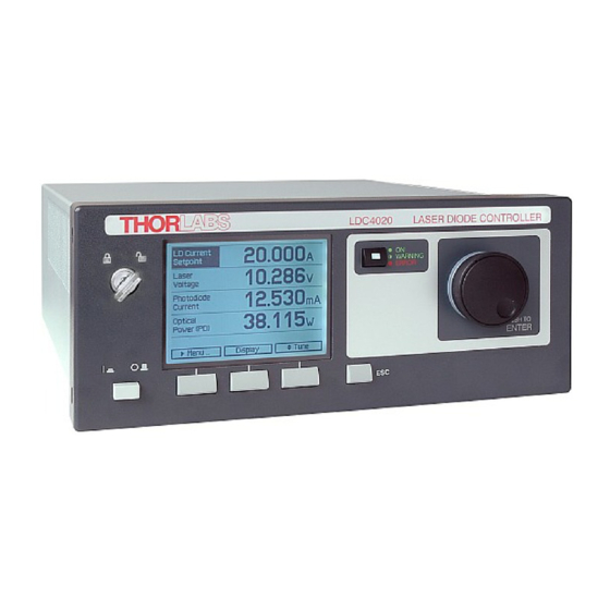
LDC4000 Series Operation Manual 2.2 Operating Elements Front Panel Key switch (Locked/Unlocked) Line switch (On/Off) LC display Softkeys for menu navigation Escape key LD On/Off button for the laser output with LD ON LED (green) and ERROR LED (red) Adjustment knob to change set values, push to enter... - Page 13 Laser diode output and optical sensor input (13W3 mixed DSUB jack) LINE IN Mains connector and fuse holder USB connector 4 mm banana jack for chassis ground DIGITAL I/O MiniDin-6 jack for 4x digital I/O, I/O supply voltage (internal +12V) and GND Copyright © 2017 Thorlabs...
-
Page 14: First Operation
Replacing the mains fuses). The LDC4000 series is immediately ready to use after turning on. The rated accuracy is reached, however, after a warming-up time of approx. 30 minutes. After switching on the unit, the graphics display will show the device status, followed by the measurement screen. -
Page 15: System Preferences
Both display parameters can be changed from 0% to 100%. The brightness value also determ- ines the illumination brightness of the adjustment knob. Note Please take care not to reduce the contrast value to a level making it impossible to read the dis- play. Copyright © 2017 Thorlabs... - Page 16 LDC4000 Series Operation Manual Sound Signals: Here you can disable or enable the audibility of the error beeps and the menu navigation click response. Line Frequency: According to the mains properties, the line filter frequency can be set to 50 Hz or 60 Hz to sup- press unwanted readout aliasing effects.
-
Page 17: Operating The Ldc4000 Series
20A current. For wiring of A1, A2, and A3 use only wires rated for at least 20A current. If Thorlabs laser diode mounts like TCLDM9, LDM21, or LM14S2 are used, the easiest way to connect them using a shielded cable CAB4005 (rated Laser current is 5A). -
Page 18: Connecting The Laser Diode
LDC4000 Series Operation Manual 3.1.2 Connecting the Laser Diode For CG polarity connect the laser diode with anode to A3 and with cathode to A1 (ground). For AG polarity, connect the laser diode with cathode to A2 and with anode to A1 (ground). Please... -
Page 19: Connecting An Optical Voltage Sensor
3 Operating the LDC4000 Series Attention Input voltage / current must not exceed 10V / 20mA! 3.1.3.2 Connecting an Optical Voltage Sensor An optical voltage sensor (like thermopile) can be connected to the 13W3 DSUB jack "LASER OUTPUT" (R9) or to the BNC jack "OPT. SENSOR IN" (R4) at the rear panel (please refer to... -
Page 20: Connecting Interlock And Ld On Monitoring
LDC4000 Series Operation Manual 3.1.5 Connecting Interlock and LD ON Monitoring The interlock function is realized using two pins that must be connected to each other as a pre- condition for switching on the laser. These are pin 5 and pin 6 of the 13W3 DSUB "LASER OUTPUT"... -
Page 21: Laser Protection "Ld Enable" Input
3 Operating the LDC4000 Series 3.1.7 Laser Protection "LD Enable" Input The LDC4000 has a "LD Enable" input for additional laser safety. Using this input, the laser di- ode can be switched off by an external TTL signal. Please connect this external "safety signal"... -
Page 22: Power-Up
LDC4000 Series Operation Manual 3.2 Power-Up Warning Prior to switching on your LDC4000, please read the safety instructions in chapter Safety care- fully. Turn on the unit by means of the line switch (F2 - see section Operating elements at the front panel). -
Page 23: Ld Output Configuration
3 Operating the LDC4000 Series 3.3 LD Output Configuration In the Laser Output configuration you can set the polarity of the driven laser diode, the switch on delay time, the laser voltage protection and the inhibit input mode of the "LD Enable" input. - Page 24 LDC4000 Series Operation Manual Noise Reduction Filter The noise reduction filter is a low pass that can be enabled to significantly decrease the laser current noise. Enabled The filter is enabled, LD current noise is reduced. Disabled No filter. Note ·...
-
Page 25: Ld Source Setup
3 Operating the LDC4000 Series 3.4 LD Source Setup Setting the operating mode: In the LD Source Setup menu you can change the operating mode of your LDC4000 between Constant Current mode and Constant Power mode. In Constant Current mode an internal cur- rent loop to the laser will be closed. - Page 26 LDC4000 Series Operation Manual The photodiode current, the thermopile voltage, and the power limit values shouldn't be set to zero, otherwise the laser current may be limited by these power limits in constant current mode. If a power limit gets active in constant current mode, the operation mode changes over to con- stant power mode.
-
Page 27: Ld Source Setpoints
3 Operating the LDC4000 Series 3.5 LD Source Setpoints You can change the set point values for constant current or constant power mode depending on the selected operating mode. To select the operating mode please refer to chapter Setting the LD source parameters. -
Page 28: Setting The Power Feedback Source Parameters
LDC4000 Series Operation Manual 3.6 Setting the Power Feedback Source Parameters To select the power feedback source please refer to chapter Setting the LD source parameters. Additional settings according to the selected sensor are described in the following two sub items. - Page 29 3 Operating the LDC4000 Series The Input Route determines the used photodiode input. The Input Route will be the contacts 7 and 8 of the 13W3 Mixed DSUB jack "LASER OUTPUT" (R9) or the BNC jack "OPT SENSOR" (R4) on the rear panel. For using the 13W3 "LASER OUTPUT" please select DSUB connector.
-
Page 30: Thermopile Input Settings
LDC4000 Series Operation Manual 3.6.2 Thermopile Input Settings For voltage sensors like thermopiles the following parameters can be set: Parameter Selection Description Input Route DSUB connector or Rear configures which input connector is used Panel BNC Range 10mV, 100mV, 1V or 10V... -
Page 31: Ld Modulation Settings
3 Operating the LDC4000 Series 3.7 LD Modulation Settings The LDC4000 provides a modulated operation of laser diodes in constant current and constant power mode. The modulation signal can be generated internally or by an external source. An internal function generator offers an AC coupled sine, triangle or square signal. The modula- tion frequency range is 20 Hz to 100 kHz for the LDC4005 and 20 Hz to 50 kHz for the LDC4020. - Page 32 LDC4000 Series Operation Manual For example; you can add a bipolar (0...±5Vmax) modulation to an internal adjusted 50% cur- rent / power value or a unipolar modulation (0...10V) if the internal adjusted "DC" value is zero. The laser current can be monitored at the “ANALOG CONTROL OUT” jack (R6) at the rear panel.
-
Page 33: Qcw Pulse Settings
3 Operating the LDC4000 Series 3.8 QCW Pulse Settings The Quasi Continuous Wave (QCW) mode allows the laser output to be pulsed with an internal or an external trigger source. All necessary pulse parameters can be set in the QCW pulse set- tings menu. - Page 34 LDC4000 Series Operation Manual Pulse frequency / Pulse period This is the pulse repetition rate in case of internal triggering. Pulse frequency is the reciprocal value of the pulse period. If you change one value the other will be readjusted automatically.
-
Page 35: Display Configuration
3 Operating the LDC4000 Series 3.9 Display Configuration The display can be configured to show two, four or six values on the screen. Factory setting is the four value screen. You can select your favorite measurement screen by pressing the Display button or in the Dis- play Configuration menu. -
Page 36: Settings Memory
LDC4000 Series Operation Manual 3.10 Settings Memory With the exception of the “LD ON” state, all settings will be saved when the LDC4000 series is powered down. Additionally, the Settings Memories menu can be useful in saving several sets of specific set- tings like: current limit, power limits, polarities, sensor input settings etc. - Page 37 3 Operating the LDC4000 Series Save Current Settings To Memory allows to save all current laser controller settings. Note that this will overwrite the settings stored in the selected data set. Via Recall Memory Settings you can load a saved laser setup. Note that this will overwrite your currently used instrument settings.
-
Page 38: Digital I/O Ports
LDC4000 Series Operation Manual 3.11 Digital I/O ports The laser diode controllers of the LDC4000 series have a very versatile digital port providing four separately configurable Input / Output lines. This feature allows control of external circuitry from the unit, or control of the unit from external circuitry (via PC software). Figure 58 shows the... - Page 39 3 Operating the LDC4000 Series I/O port source operation In above circuit, the output drives an optocoupler in source operation. This component may be replaced by a LED or a switching transistor. To switch the connected device to on-state, the output level of the digital I/O line must be set HIGH.
- Page 40 For enhanced controlling, please use the remote control interface from an external PC or Laptop. See the Thorlabs “Series 4000 Programmers Reference Manual” on the included “Ser- ies 4000 Instrumentation CD”.
-
Page 41: System Preferences
3 Operating the LDC4000 Series 3.12 System Preferences The System Preferences menu allows to select different settings concerning your LDC4000 system configuration, including Message Handling, Display Brightness, Display Contrast, Sound Signals, and Update Capability. For detailed explanations please see section Getting Started - System Preferences. -
Page 42: Computer Interface
Via the instrument's USB interface you may easily connect to third party data logging, data ac- quisition and data analysis software (e.g. MATLAB, NI LabVIEW Signal Express, Agilent VEE). For basic instrument communication you may also use the Thorlabs Instrument Communicator 2 Software from the accompanying data carrier. Please see also the SCPI Programmers Refer- ence Manual for a detailed description of the instrument's command set. -
Page 43: Instrument Driver Installation
Various programming examples demonstrate how to use the instrument driver and how to com- municate successfully with your instrument. The examples are installed with the instrument driver and may be found in the drivers installation directory. Copyright © 2017 Thorlabs... -
Page 44: Firmware Update
Firmware upgrades can be accomplished by the user via the USB interface using the software "Thorlabs DFU Wizard". Note To install the Thorlabs DFU wizard successfully, you must have Administrator privileges on the PC, and the instrument must be powered down or disconnected from the USB. Follow the instructions below to upgrade your instrument: ·... -
Page 45: Maintenance And Service
75% Isopropyl Alcohol solution for more efficient cleaning. 5.2 Line Voltage Settings The LDC4000 series laser diode controllers operate with line voltages of 100 ... 120 V AC and 200 ... 240 V AC ±10%. The line frequency range is 50 ... 60 Hz. -
Page 46: Replacing The Mains Fuses
3. Replace the defective fuses (R15). We recommend changing both fuses, even if only one fuse has opened. Press in the fuse holder into the mains jack until locked on both sides. 4. Switch on the unit. If it cannot be switched on, please contact your supplier or Thorlabs. Copyright © 2017 Thorlabs... -
Page 47: Troubleshooting
· If you don’t find the error source by means of the trouble shooting list please first contact Thorlabs before sending the LDC40xx laser diode controller for checkup and repair to Thorlabs (refer to section Thorlabs Worldwide contacts). -
Page 48: Appendix
LDC4000 Series Operation Manual 6 Appendix 6.1 Technical Data LDC4005 LDC4020 Laser Current Control (Constant Current Mode) Laser diode current range 0 to 5 A 0 to 20 A Compliance voltage 12 V 11 V 1 mA / 80 µA 1 mA / 320 µA... - Page 49 1 mV/V /10 mV/V / 100 mV/V / 1V/V ±5% Modulation coefficient, CP mode, Voltage Sensor Internal laser modulation Waveforms Sine, Square, Triangle Frequency range 20 Hz to 100 kHz 20 Hz to 50 kHz Modulation depth 0.1 to 100% Copyright © 2017 Thorlabs...
- Page 50 LDC4000 Series Operation Manual LDC4005 LDC4020 QCW Mode Pulse width range 0.1 ms to 1 s Pulse width resolution 1 µs Repetition rate range 1 ms to 5 s ( 0.2 to 1000 Hz) Repetition rate resolution 10 µs Trigger...
- Page 51 Dimensions (WxHxD) with operating elements 263 x 122 x 345 mm³ via front panel / remote control depending on selected measurement range All technical data are valid at 23 ± 5°C and 45 ± 15% rel. humidity (non condensing) Copyright © 2017 Thorlabs...
-
Page 52: Menu Structure Overview
LDC4000 Series Operation Manual 6.2 Menu Structure Overview Menu topic description LD Output Configuration Laser diode polarity, laser diode voltage protection, switch on delay, and inhibit input mode can be set LD Source Setup Operating mode, laser current limit, photodiode current limit,... -
Page 53: Factory Settings For Ldc40Xx
Feedback Loop Speed 0.1% Modulation Modulation Source Internal Shape Sine Frequency 1 kHz Depth QCW Trigger internal QCW Pulse Period 20 ms QCW Pulse Width 1 ms Display 4 value screen Display Value 1 LD Source set point Copyright © 2017 Thorlabs... - Page 54 LDC4000 Series Operation Manual Set Value Factory Setting Display Value 2 LD Current Reading Display Value 3 LD Voltage Reading Display Value 4 Photodiode Current Reading Display Brightness 100 % Display Contrast 65 % Sound Signals Enabled Line Frequency Auto...
-
Page 55: Error Messages
Temp. Protection Mode (Output Enable) active* Critical errors: · Keylock · LD open · Interlock · Inhibit Input Mode (Protection)* · Temperature Protection (Protection)* Red flashing Internal device overtemperature (OTP) * Refer to section Laser Output Configuration Copyright © 2017 Thorlabs... -
Page 56: Status Indicators
LDC4000 Series Operation Manual 6.4.2 Status Indicators The LDC4000 has various status indicators in the displays bottom line. The meanings are: Status indicator Description The key switch is in locked position to prevent unauthorized usage of the laser driver. The interlock is open because of an open safety switch or an incorrect INTERL wiring or an open safety switch;... -
Page 57: Instrument Errors
Operation is not allowed while the photodiode BIAS is switched on. Not permitted with QCW mode on The constant power mode is not allowed if the QCW mode is switched on, please set the QCW mode to off before using constant the power mode Copyright © 2017 Thorlabs... - Page 58 FPGA configuration error A FPGA configuration failure has occurred during the boot procedure, please switch the unit off and on again. If this error is shown again contact the Thorlabs Hotline Nonvolatile checksum error A general EEPROM checksum error has occured, please switch the unit off and on again.
- Page 59 6 Appendix Error Description Self test failed The device self test procedure has failed, please switch the unit off and on again. If this error continues contact the Thorlabs Hotline Copyright © 2017 Thorlabs...
-
Page 60: Certifications And Compliances
LDC4000 Series Operation Manual 6.5 Certifications and Compliances This product was tested for and complies with the following standards: · CAN/CSA-C22.2 No. 61010-1-04 · ANSI/UL 61010-1-2004 Copyright © 2017 Thorlabs... -
Page 61: Warranty
For warranty repairs or service the unit must be sent back to Thorlabs. The customer will carry the shipping costs to Thorlabs, in case of warranty repairs Thorlabs will carry the shipping costs back to the customer. -
Page 62: Exclusion Of Reliability And Copyright
LDC4000 Series Operation Manual 6.7 Exclusion of Reliability and Copyright Thorlabs has taken every possible care in preparing this document. We however assume no li- ability for the content, completeness or quality of the information contained therein. The content of this document is regularly updated and adapted to reflect the current status of the hardware and/or software. -
Page 63: Thorlabs "End Of Life" Policy (Weee)
Waste treatment on your own responsibility If you do not return an “end of life” unit to Thorlabs, you must hand it to a company specialized in waste recovery. Do not dispose of the unit in a litter bin or at a public waste disposal site. -
Page 64: List Of Acronyms
LDC4000 Series Operation Manual 6.9 List of Acronyms Alternating Current Anode Grounded Constant Current Cathode Grounded Constant Power Continuous Wave Direct Current Digital Direct Synthesizer I (current) of Laser Diode I (current) of Photodiode Input / Output Laser Diode Laser Diode Controller... -
Page 65: Thorlabs Worldwide Contacts
Email: europe@thorlabs.com Email: scandinavia@thorlabs.com France Brazil Thorlabs SAS Thorlabs Vendas de Fotônicos Ltda. 109, rue des Côtes Rua Riachuelo, 171 78600 Maisons-Laffitte São Carlos, SP 13560-110 France Brazil Tel: +33-970 444 844 Tel: +55-16-3413 7062 Fax: +33-811 38 17 48 Fax: +55-16-3413 7064 www.thorlabs.com... - Page 66 www.thorlabs.com...
Need help?
Do you have a question about the LDC4000 Series and is the answer not in the manual?
Questions and answers