Toshiba B-SX6T Series Owner's Manual
Toshiba barcode printer owner's manual
Hide thumbs
Also See for B-SX6T Series:
- System mode manual (133 pages) ,
- Option installation manual (31 pages) ,
- Maintenance manual (24 pages)

Related Manuals for Toshiba B-SX6T Series


Summary of Contents for Toshiba B-SX6T Series
- Page 1 TOSHIBA Barcode Printer B-SX6T SERIES Owner’s Manual Mode d’emploi Bedienungsanleitung Manual de instrucciones Gebruikershandleiding Manuale Utente Manual do Utilizador...
- Page 2 “Cet appareil numérique de la classe A respecte toutes les exigences du Règlement sur le matériel brouilleur du Canada.” < For EU Only > TOSHIBA TEC Europe Retail Information Systems S.A. Rue de la Célidée 33 BE-1080 Brussels IP20 (for USA only) (for CANADA only) Copyright ©...
- Page 3 TOSHIBA Barcode Printer B-SX6T SERIES Owner's Manual...
- Page 4 Waste Recycling information for users: Following information is only for EU-member states: The use of the crossed-out wheeled bin symbol indicates that this product may not be treated as general household waste. By ensuring this product is disposed of correctly you will help prevent potential negative consequences for the environment and human health, which could otherwise be caused by inappropriate waste handling of this product.
-
Page 5: For Safety
If you have any reason to suspect that interference is taking place, immediately turn off the product and contact your TOSHIBA TEC sales agent. -
Page 6: Safety Summary
Do not attempt to effect repairs or modifications to this equipment. If a fault occurs that cannot be rectified using the procedures described in this manual, turn off the power, unplug the machine, then contact your authorised TOSHIBA TEC representative for assistance. Meanings of Each Symbol This symbol indicates warning items (including cautions). - Page 7 • Utilize our maintenance services. After purchasing the machine, contact your authorised TOSHIBA TEC representative for assistance once a year to have the inside of the machine cleaned. Otherwise, dust will build up inside the machines and may cause a fire or a malfunction. Cleaning is particularly effective before humid rainy seasons.
-
Page 8: Table Of Contents
PRODUCT OVERVIEW... E1- 1 Introduction... E1- 1 Features ... E1- 1 Accessories ... E1- 2 Appearance ... E1- 3 1.4.1 Dimensions...E1- 3 1.4.2 Front View ...E1- 3 1.4.3 Rear View ...E1- 3 1.4.4 Operation Panel...E1- 4 1.4.5 Interior ...E1- 4 Options ...E1- 5 PRINTER SETUP ... - Page 9 CAUTION! 1. This manual may not be copied in whole or in part without prior written permission of TOSHIBA TEC. 2. The contents of this manual may be changed without notification.
-
Page 10: Product Overview
1. PRODUCT OVERVIEW 1.1 Introduction 1.2 Features Thank you for choosing the TOSHIBA B-SX6T series thermal printer. This Owner’s Manual contains from general set-up through how to confirm the printer operation using an online test print, and should be read carefully to help gain maximum performance and life from your printer. -
Page 11: Accessories
Accessories NOTE: As a power cord is not supplied with this printer, please purchase one that meets each country’s safety standard. For details, refer to APPENDIX 3. When unpacking the printer, please make sure all the following accessories are supplied with the printer. Start-up CD-ROM (1 pc.) <Contents>... -
Page 12: Appearance
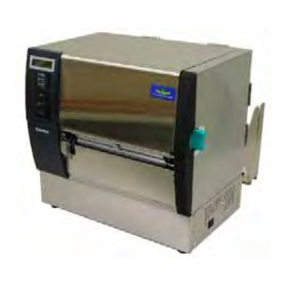
1.4 Appearance 1.4.1 Dimensions 1.4.2 Front View 1.4.3 Rear View The names of the parts or units introduced in this section are used in the following chapters. 417 (16.4 ) LCD Message Display Operation Panel Media Outlet Parallel Interface Connector (Centronics) Media Guide Media Holder... -
Page 13: Operation Panel
1.4.4 Operation Panel 1.4.5 Interior WARNING! 1. Do not touch the Print Head or around it just after printing. You may get burned as the Print Head becomes very hot during printing. 2. Do not touch any moving parts. To reduce the risk of fingers, jewellery, clothing, etc., being drawn into the moving parts, be sure to load... -
Page 14: Options
B-SX908-MC-QM-R Cover (Future Option) NOTE: To purchase the optional kits, please contact the nearest authorised TOSHIBA TEC representative or TOSHIBA TEC Head Quarters. Usage A cutter which cuts the media one by one. This module peels off a printed label from the backing paper at the media outlet. -
Page 15: Printer Setup
2. PRINTER SETUP This section outlines the procedures to setup your printer prior to its operation. The section includes precautions, loading media and ribbon, connecting cables, setting the operating environment of the printer, and performing an online print test. Setup Flow Installation Assembling the supply holder frame... -
Page 16: Installation
2. PRINTER SETUP 2.1 Installation 2.2. Assembling the Supply Holder Frame To insure the best operating environment, and to assure the safety of the operator and the equipment, please observe the following precautions. • Operate the printer on a stable, level, operating surface in a location free from excessive humidity, high temperature, dust, vibration or direct sunlight. -
Page 17: Connecting The Power Cord
2.3 Connecting the Power Cord CAUTION! As a Power Cord is not supplied with the printer, please purchase an approved on that meets the safety standard of each country. (Refer to APPENDIX 3.) 1. Make sure that the printer Power Switch is in the OFF ( ) position. Connect the Power Cord to the printer as shown in the figure below Power Switch 2. -
Page 18: Loading The Media
2. PRINTER SETUP 2.4 Loading the Media WARNING! 1. Do not touch any moving parts. To reduce the risk of fingers, jewellery, clothing, etc., being drawn into the moving parts, be sure to load the media once the printer has stopped moving completely. - Page 19 2.4 Loading the Media (Cont.) 4. Install the other Media Holder onto the Supply Shaft from the opposite side. 5. Turn the Locking Lever of the Media Holder to the “Close” position. “Close” Position Media 6. Set the Head Lever to the “OPEN” position. Head Lever 7.
- Page 20 2.4 Loading the Media (Cont.) WARNING! Be careful not to pinch your fingers or hands by the Supply Holder Frame or Media Holders when loading the media. NOTE: Place the bushes of the Supply Shaft into the notches of the Supply Holder Frame securely.
- Page 21 2.4 Loading the Media (Cont.) NOTES: 1. When using the Movable sensor, choose the Movable sensor for the parameter setting in the system mode (Section 2.8.1 Parameter Setting). The Fixed sensor has been selected as default. 2. The position of the movable sensor should be adjusted before loading the ribbon.
- Page 22 2.4 Loading the Media (Cont.) NOTE: Adjustment Knob Forward: Moves toward the centre of the printer. Backward: Moves away from the centre of the printer. The following procedures show how to adjust the position of the movable sensor. Feed Gap Sensor position adjustment When using a label stock without black marks, the Feed Gap Sensor is used to detect the print start position.
- Page 23 2. PRINTER SETUP 2.4 Loading the Media (Cont.) NOTE: Be sure to set the Black Mark Sensor to detect the centre of the black mark, otherwise a paper jam or no paper error may occur. Black Mark Sensor position adjustment When using media with black marks, the Black Mark Sensor is used to detect the print start position.
- Page 24 2.4 Loading the Media (Cont.) 14. There are three issue modes available on this printer. How to set the media for each mode is provided below. Batch mode In the batch mode, the media is continuously printed and fed until the number of labels/tags specified in the issue command have been printed.
- Page 25 2.4 Loading the Media (Cont.) WARNING! When the Backing Paper Release Bar is released, it is automatically closed by the spring. Care must be taken not to pinch your fingers or hands. Strip mode (Option) When the optional Strip Module is fitted, a label is automatically removed from the backing paper at the Strip Plate as each label is printed.
- Page 26 2.4 Loading the Media (Cont.) WARNING! The cutter is sharp, so care must be taken not to injure your fingers when handling the cutter. CAUTION! 1. When using a label stock, be sure to cut the gaps. Cutting labels will cause the glue to stick to the cutter, which may affect the cutter quality and shorten the cutter life.
- Page 27 2.4 Loading the Media (Cont.) 15. Change the print head pressure according to the thickness of the media to be used, by using the Head Lever. Position Media type or thickness Label or Thin media If a clear print cannot be obtained, change the position to Tag paper or Thick paper If a clear print cannot be obtained,...
-
Page 28: Loading The Ribbon
2.5 Loading the Ribbon WARNING! 1. Do not touch any moving parts. To reduce the risk of fingers, jewellery, clothing, etc., being drawn into the moving parts, be sure to load the ribbon once the printer has stopped moving completely. 2. - Page 29 2.5 Loading the Ribbon (Cont.) 4. Fit the core of the Ribbon Supply Roll into the Ribbon Holders (Supply side), aligning the notch of the ribbon core with the protrusion of the Ribbon Holder. Ribbon Supply Roll Ribbon Holder (Supply Side) Fit the protrusion into the notch.
- Page 30 2.5 Loading the Ribbon (Cont.) NOTES: 1. Be sure to remove any slack in the ribbon when printing. Printing with a wrinkled ribbon will lower the print quality. 2. When a ribbon end is detected, “RIBBON ERROR” message will appear on the display and the ERROR LED will illuminate.
-
Page 31: Connecting The Printer To Your Host Computer
2.6 Connecting the Printer to Your Host Computer CAUTION! Do not directly connect the LAN cable which is wired outside of a building to the LAN port provided on this product, as the LAN port on this product is intended for indoor connection. To connect such LAN cable to the product, be sure to use any communication equipment, like... -
Page 32: Turning The Printer On
2.7 Turning the Printer CAUTION! Use the power switch to turn the printer On/Off. Plugging or unplugging the Power Cord to turn the printer On/Off may cause fire, an electric shock, or damage to the printer. NOTES: 1. If a message other than ON LINE appears on the display or the ERROR LED (Red) is illuminated, go to Section 5.1,... -
Page 33: Setting An Operating Environment
TOSHIBA TEC service representative. For the settings this manual does not cover, please contact your nearest TOSHIBA TEC service representative, or refer to the B-SX6T/SX8T Series Key Operation Specification stored in the CD-ROM. How to enter the System Mode 1. -
Page 34: Parameter Setting
2.8.1 Parameter Setting While “<2>PARAMETER SET” is displayed on the LCD Message Display, press the [PAUSE] key to enter the Parameter Setting Mode. The Parameter Setting Mode contains the following sub menus. Each time the [PAUSE] key is pressed, the sub menus are displayed sequentially. - Page 35 2.8.1 Parameter Setting (Cont.) NOTE: Be careful if the printer is turned off without pressing the [PAUSE] key, the selected value does not become effective. NOTE: The following fonts do not support a zero with slash. Bit Map Font: OCR-A, OCR-B, GOTHIC 725 Black, Kanji, Chinese Outline Font: Price Font 1, Price Font 2, Price...
- Page 36 2.8.1 Parameter Setting (Cont.) <Reference> Properties screen of Serial (COM) port under Windows98 (3) Baud Rate Selection This parameter is to choose a baud rate of the RS-232C interface. When the printer communicates with a host computer by serial interface, be sure to match the setting with the host.
- Page 37 2. PRINTER SETUP 2.8.1 Parameter Setting (Cont.) NOTES: 1. When using the hardware flow control, the control signals and data must be in pairs between the printer and the PC. Printer Host → ← → ← → ← Refer to the RS-232C connector’s pin layout in APPENDIX 2.
- Page 38 2.8.1 Parameter Setting (Cont.) NOTES: 1. If the printer is not used for a few days, the top edge of the media may become curly, which may cause a paper jam. The Auto Forward Wait Function prevents this problem since the media feed amount is increased so that the media stops past the platen.
- Page 39 2.8.1 Parameter Setting (Cont.) NOTE: The print head may not be raised depending on the rise of the solenoid’s temperature. When ON is selected, pressing the [PAUSE] key will result that the LCD Message Display shows the stop position fine adjustment value setting screen.
- Page 40 2.8.1 Parameter Setting (Cont.) NOTES: 1. The ribbon saving function is available only when an optional ribbon saving module (B-SX908- R-QM-R) is installed. 2. The ribbon saving function is activated when there is a 20-mm or more non-print area in the media feed direction.
- Page 41 2.8.1 Parameter Setting (Cont.) When “CODE MANUAL” is selected and the [PAUSE] key is pressed, the LCD display will show the setting screen of CONTROL CODE1 to CONTROL CODE3 as follows. <2>PARAMETER SET CONTROL CODE1 1B CONTROL CODE1 FF [RESTART] CONTROL CODE1 FE CONTROL CODE1 FD [FEED]...
- Page 42 2. PRINTER SETUP 2.8.1 Parameter Setting (Cont.) (14) Strip Wait Status Selection This parameter is to choose when the printer sends a strip wait status (05H) to a host in response to a status request command. When “<2>PARAMETER SET” appears, press the [PAUSE] key until the following display appears.
- Page 43 2.8.1 Parameter Setting (Cont.) NOTE: Kanji code selection is not supported by the QM model as the Kanji ROMs are not installed. NOTE: Pressing the [FEED] or [RESTART] key causes 1 byte change in the Euro Code value. (16) KANJI Code Selection This parameter is to choose a KANJI code.
- Page 44 2.8.1 Parameter Setting (Cont.) NOTES: 1. It is recommended that this function should be activated when high quality printing such as bar codes printing is required. Otherwise, choose OFF. 2. When a broken element is found, the printer stops, displaying “HEAD ERROR”.
- Page 45 2.8.1 Parameter Setting (Cont.) NOTE: When “WEB PRINTER ON” is selected, the status of the printer connected in a network can be checked through the Web browser. (20) Web Printer Function Selection This parameter is to choose whether to use the printer as a web printer. When “<2>PARAMETER SET”...
- Page 46 2.8.1 Parameter Setting (Cont.) (22) Input Prime Selection This parameter is to choose whether to enable a reset operation when INIT signal is ON. Normally, when the printer receives a reset request signal (nInit signal) from the host via Centronics interface, the printer will be reset and turn to the idle state.
- Page 47 2.8.1 Parameter Setting (Cont.) NOTE: If the printer and the PC are connected by USB, plug & play will be automatically enabled, regardless of the setting of this parameter. (24) Plug & Play Selection This parameter is to choose whether to enable a Plug & Play function. When “<2>PARAMETER SET”...
- Page 48 2.8.1 Parameter Setting (Cont.) (26) Pre-Strip Selection This parameter is to choose whether to activate the Pre Strip function. When this parameter is set to ON (Available), the top edge of a label is separated (pre-stripped) from the backing paper before the label is printed. This function is intended to make the strip issue easier in case the labels are hard to strip due to the label intensity, adhesive power, or the printing speed.
- Page 49 2.8.1 Parameter Setting (Cont.) NOTE: The stabilizer function is available only to the thermal direct print mode. (28) Maxi Code Specification Selection This parameter is to choose a Maxi code specification. When “<2>PARAMETER SET” appears, press the [PAUSE] key until the following display appears.
-
Page 50: Dump Mode Setting
2.8.2 Dump Mode Setting NOTES: 1. When “ON DEMAND” is selected, it is required to choose a printing method again and press the [PAUSE] key to print the subsequent data until the all data has been printed. If an error occurs during dumping, the printer will display an error message and stop printing. -
Page 51: Receive Buffer Size
2.8.2 Dump Mode Setting (Cont.) Print Conditions • Printing width: 3.9 inches (100 mm) • Sensor selection: None • Print speed: 4”/sec. • Printing mode: Depends on the selection in use. • 16 bytes/line • Data is printed in the order from the new one to the old one. -
Page 52: Basic Expansion Mode
2.8.3 BASIC Expansion Mode NOTE: For the BASIC enable setting mode, refer to the B-SX6T/SX8T Series Key Operation Specification stored in the CD-ROM. While “<5>EXPAND MDOE” is displayed on the LCD Message Display, press the [PAUSE] key to enter the BASIC Expansion Mode. In the BASIC Expansion Mode, it is possible to execute the BASIC expansion mode program under the following conditions. -
Page 53: Automatic Calibration
2.8.4 Automatic Calibration While “<6>AUTO CALIB” is displayed on the LCD Message Display, press the [PAUSE] key to enter the Automatic Calibration Mode. In the Automatic Calibration Mode, whether to activate the automatic calibration at a power on time or not is selectable. When the automatic calibration is activated, the printer feeds the media for about 160 mm each time the power is turned on or the Top Cover is opened, to detect a print start position. -
Page 54: Lan Setting
2.8.5 LAN Setting While “<7>LAN” is displayed on the LCD Message Display, press the [PAUSE] key to enter the LAN Setting Mode. In the LAN Setting Mode, whether to enable the LAN communication and SNMP or not is selectable. When “<7>LAN” appears, press the [PAUSE] key. <7>LAN ON SNMP ON Use the [FEED] or [RESTART] key to select a desired option. -
Page 55: Real Time Clock Setting
2.8.6 Real Time Clock Setting NOTE: The Real Time Clock Setting is effective only when an optional Real Time Clock, B-SA704-RTC-QM-R, is installed. NOTE: Use the [FEED] or [RESTART] key to set the value. While “<8>RTC SET” is displayed on the LCD Message Display, press the [PAUSE] key to enter the Real Time Clock Setting Mode. - Page 56 2.8.6 Real Time Clock Setting (Cont.) NOTE: 1. Be sure to load the battery and set the low battery check function to ON whenever the real time clock is used. If the battery is not loaded or the battery voltage is low, the real time clock data is erased at the power off time.
-
Page 57: Ip Address Setting (Tcp/Ip)
2.8.7 IP Address Setting (TCP/IP) Power OFF While holding down the [FEED] and [PAUSE] keys, turn on the printer. <1>DIAG. Vx.x [FEED] [RESTART] <2>PARAMETER SET [FEED] [RESTART] <3>ADJUST SET [FEED] [RESTART] <4>TEST PRINT [FEED] [RESTART] <5>SENSOR ADJ. [FEED] [RESTART] <6>RAM CLEAR [FEED] [RESTART] <7>IP ADDRESS... - Page 58 2.8.7 IP Address Setting (TCP/IP) (Cont.) In this section, how to set the IP address is described. First, you need to access the System Mode for system administrators. 1. While holding down the [FEED] and [PAUSE] keys, turn on the printer.
- Page 59 2.8.7 IP Address Setting (TCP/IP) (Cont.) NOTES: 1. Set each 3-digit value by using the [RESTART] or [FEED] key. [RESTART] key: Increment [FEED] key: Decrement Range: 0 to 255 2. Press the [PAUSE] key to move the cursor to the next 3-digit value.
-
Page 60: Ip Address Setting
2.8.7 IP Address Setting (TCP/IP) (Cont.) NOTE: After the last 3-digit value is set, press the [PAUSE] key to go to Socket Port Setting. NOTES: 1. Pressing the [PAUSE] key while “PORT ON 08000” is displayed allows you to set the port number. - Page 61 2.8.7 IP Address Setting (TCP/IP) (Cont.) NOTE: Pressing the [PAUSE] key while “DHCP ON” is displayed allows you to set a DHCP client ID. NOTES: 1. Code used to enter a DHCP client ID is selectable between ASCII code (alphanumeric) and Hex code.
- Page 62 & ‘ < > SP = Space (Example) To enter “TOSHIBA” in Hex. code: 54 4F 53 48 49 42 41 When the system mode settings have been completed, turn off the printer. E2-48 ENGLISH VERSION EO1-33056 2.8 Setting an Operating Environment...
-
Page 63: Printer Setup
Installing the Printer Drivers 2.9.1 Introduction This manual describes how to install the TOSHIBA printer driver for the TOSHIBA bar code printer on your Windows host computer; install and delete the printer driver, the procedure for adding the LAN port, cautions and limitations. -
Page 64: Installing The Printer Driver
2.9.3 Installing the Printer Driver The installation procedure differs depending on the interface connected to the printer and the operation system you are using. Please install the printer driver by performing the appropriate procedure. If the previous version of the printer driver has been installed on your host computer , be sure to uninstall it before you install this printer driver. - Page 65 Windows 98/Me Select “Settings” – “Printers” from the “Start” menu to open the printer folder. (2) Double-click on the “Add Printer” icon. The Add Printer Wizard runs. Click on the [Next] button. (3) Select “Local printer”, then click on the [Next] button. The screen listing “Manufacturers and Printers”...
- Page 66 (6) The screen to select the existing installed printer driver or use the new one, is displayed. Select “Replace existing driver”, then click on the [Next] button. If you install the printer driver for the first time, this screen is not displayed. (7) Select the port to be used for printing from the “Available ports”...
- Page 67 Windows 2000/XP (1) Log on to your host computer as a member who has full control access privilege concerning the printer settings. (2) Select “Settings” – “Printers” from the “Start” menu to open the printer folder. (3) Double-click on the “Add Printer” icon. The Add Printer Wizard runs. Click on the [Next] button. (4) Select “Local printer”.
- Page 68 (9) The “Use Existing Driver” screen is displayed. Select “Replace existing driver”, then click on the [Next] button. If you install the printer driver for the first time, this screen is not displayed. (10) Change the printer name if necessary, and select whether or not you use the printer as the default printer (“Yes”...
-
Page 69: Usb Interface
(2) USB INTERFACE Installation starts by the operating system’s plug-and-play function. Windows 98/Me (1) Turn the printer ON, then connect it to your host computer with the USB cable. The “New Hardware Found” dialog box is displayed, and “USB Device” is detected. (2) After a while, the “Add New Hardware Wizard”... - Page 70 (3) Select “Search for the best driver for your device. (Recommended)”. Mark the “Specify a location” checkbox, then click on the [Browse] button. Specify “\driver” folder, then click on the [Next] button. (4) Check to see that the “USB Printing Support” driver is detected, then click on the [Next] button. E2-56 ENGLISH VERSION EO1-33056 2.9 Installing the Printer Drivers...
- Page 71 (5) When the screen which indicates the USB Printing Support driver has been installed, is displayed, click on the [Finish] button. (6) After a while, “TEC B-SA4T” is detected as a new hardware. (7) The “Add New Hardware Wizard” dialog box is displayed. Select “Specify the location of the driver (Advanced)”, then click on the [Next] button.
- Page 72 (8) Select “Search for the best driver for your device. (Recommended)”. Mark the “Specify a location” checkbox, then click on the [Browse] button. Specify “\driver” folder, then click on the [Next] button. (9) Check to see that the “TEC B-SA4T” driver is detected, then click on the [Next] button. E2-58 ENGLISH VERSION EO1-33056 2.9 Installing the Printer Drivers...
- Page 73 (10) Change the printer name if necessary, and select whether or not you use the printer as the default printer (“Yes” or “No”). Click on the [Finish] button. (11) When the screen, which indicates TEC B-SA4T has been installed, is displayed, click on the [Finish] button.
- Page 74 Windows 2000/XP NOTE: When plug-and-play printer installation in progress is stopped, be sure to delete the printer detected and displayed on the “Device Manager” tab of the “System Properties” dialog box. (1) Log on to your host computer as a member who has full control access privilege concerning the printer settings.
- Page 75 (6) Select “Install from a list or specific location (Advanced)”, then click on the [Next] button. (7) Select “Search for the best driver in these locations”. Mark the “Include this location in the search” checkbox, then click on the [Browse] button. Specify the “\driver”...
- Page 76 2. PRINTER SETUP ENGLISH VERSION EO1-33056 2.9 Installing the Printer Drivers (8) When the dialog box below is displayed, click on the [Continue Anyway] button. (9) When the “Completing the Found New Hardware Wizard” screen is displayed, click on the [Finish] button.
-
Page 77: Uninstalling The Printer Driver
2.9.4 Uninstalling the Printer Driver NOTE: Before uninstalling the printer driver, be sure to complete all of printing, the status monitor, and properties settings. Windows 98/ME (1) Select “Settings” – “Printers” from the “Start” menu to open the printer folder. (2) Right-click on the printer driver icon to be deleted, then select “Delete”. -
Page 78: Adding/Deleting A Lan Port
To use the LAN interface, first, you have to make the following settings in “<7> IP ADDRESS” in the system mode of the printer. (Refer to TOSHIBA TEC support representative.) • Set the printer IP address (“PRINTER IP ADRES”), the gateway IP address (“GATEWAY IP ADRES”), and subnet mask (“SUBNET MASK”). - Page 79 Windows 2000/XP (1) Right-click on the printer icon. Select “Properties” to open the printer “Properties” dialog box. (2) Select the “Ports” tab, and click on the [Add Port…] button. The “Printer Ports” dialog box is displayed. (3) Select “Seagull Scientific TCP/IP Port” from the “Available Printer Ports” list, then click on the [OK] button.
-
Page 80: Cautions
2.9.6 Cautions (1) Printer Driver Upgrades • To upgrade the printer driver to this version, uninstall the previous version of the printer driver, before installing this printer driver. • Be sure to restart your host computer, after you upgrade the printer driver. •... -
Page 81: Using The Printer Driver
2.9.7 Using the Printer Driver For how to use the Printer Driver, please refer to the Help for Windows Printer Drivers screen. Open the Properties screen of the Printer Driver. Clicking on the About tab causes the following screen to appear. Click on the [Help] button. -
Page 82: Print Test
2.10 Print Test After your operating environment has been set, perform a print test. 1. Perform a print test by using the Printer Driver or an Issue Command. The printer driver’s Properties screen allows you to set the communication conditions, media size, and other printing conditions in accordance with your operating environment. - Page 83 2. PRINTER SETUP ENGLISH VERSION EO1-33056 2.10 Print Test 2.10 Print Test (Cont.) When using an optional Cutter Module or Strip Module It is necessary to set the issue mode, cut/strip position, etc. for the Printer Driver or TPCL (TEC Printer Command Language) in accordance with your printing condition.
-
Page 84: Position And Print Tone Fine Adjustment
2.11 Position and Print Tone Fine Adjustment <3>ADJUST SET [PAUSE] <3>ADJUST SET FEED ADJ.+10.0mm [PAUSE] <3>ADJUST SET CUT ADJ. +10.0mm [PAUSE] <3>ADJUST SET BACK ADJ. +5.0mm [PAUSE] <3>ADJUST SET X ADJUST +50.0mm [PAUSE] <3>ADJUST SET TONE ADJ.<T> +3 [PAUSE] <3>ADJUST SET TONE ADJ.<D>... - Page 85 2.11 Position and Print Tone Fine Adjustment (Cont.) NOTES: Choose a desired value by using the [RESTART] or [FEED] key. Pressing the [FEED] key one time causes a –0.1mm change, up to –50.0 mm. Pressing the [RESTART] key one time causes a +0.1mm change, up to +50.0 mm.
- Page 86 2.11 Position and Print Tone Fine Adjustment (Cont.) NOTES: Choose a desired value by using the [RESTART] or [FEED] key. Pressing the [FEED] key one time causes a –0.1mm change, up to –50.0 mm. Pressing the [RESTART] key one time causes a +0.1mm change, up to +50.0 mm.
- Page 87 2. PRINTER SETUP ENGLISH VERSION EO1-33056 2.11 Position and Print Tone Fine Adjustment • Example of Strip Position Fine Adjustment When setting +3.0 mm Print Head Compared with “+0.0mm” position, the stop position Label after printing is shifted forward. Platen Stop position after Strip Plate printing...
- Page 88 2.11 Position and Print Tone Fine Adjustment (Cont.) NOTES: Choose a desired value by using the [RESTART] or [FEED] key. Pressing the [FEED] key one time causes a –0.1mm change, up to –9.9 mm. Pressing the [RESTART] key one time causes a +0.1mm change, up to +9.9 mm.
- Page 89 2.11 Position and Print Tone Fine Adjustment (Cont.) NOTES: Choose a desired value by using the [RESTART] or [FEED] key. Pressing the [FEED] key one time causes a –0.1mm change, up to –99.9 mm. Pressing the [RESTART] key one time causes a +0.1mm change, up to +99.9 mm.
- Page 90 2.11 Position and Print Tone Fine Adjustment (Cont.) NOTES: Choose a desired value by using the [RESTART] or [FEED] key. Pressing the [FEED] key one time causes a –1 tone change, up to –10 tones. Pressing the [RESTART] key one time causes a +1 tone change, up to +10 tones.
- Page 91 2.11 Position and Print Tone Fine Adjustment (Cont.) NOTES: Choose a desired value by using the [RESTART] or [FEED] key. Pressing the [FEED] key one time causes a –1 step change, up to –15 steps. Pressing the [RESTART] key one time causes a +1 step change, up to +0 steps.
-
Page 92: Threshold Setting
2.12 Threshold Setting NOTES: 1. Failure to feed more than 1.5 labels may result in an incorrect threshold setting. 2. While the Top Cover is raised, the [PAUSE] key does not work 3. A paper end error cannot be detected during paper feed. To maintain a constant print position the printer uses the media sensor to detect a print start position according to the difference of voltage between a print area and a gap or black mark. - Page 93 2.12 Threshold Setting (Cont.) <5>SENSOR ADJ. [PAUSE] <5>SENSOR ADJ. [H]28°C [A]28°C [PAUSE] <5>SENSOR ADJ. [REFLECT] 3.5V [FEED] or [RESTART] <5>SENSOR ADJ. [REFLECT] 4.8V* [PAUSE] <5>SENSOR ADJ. [TRANS.] 2.4V [FEED] or [RESTART] <5>SENSOR ADJ. [TRANS.] 4.1V* [PAUSE] <5>SENSOR ADJ. [PE]R0.1V T4.8V [FEED] or [RESTART] <5>SENSOR ADJ.
- Page 94 2.12 Threshold Setting (Cont.) Voltage at a black mark Midpoint (Threshold voltage) Voltage at a print area <5>SENSOR ADJ. [REFLECT] 3.5V <5>SENSOR ADJ. [REFLECT] 4.8V* <5>SENSOR ADJ. [TRANS.] 2.4V Voltage at a label gap Midpoint (Threshold voltage) Voltage at a print area <5>SENSOR ADJ.
- Page 95 2.12 Threshold Setting (Cont.) Storing a “No Media Level” Voltage The following is how to set a “No media level” voltage that is used to detect a paper end. If a “NO PAPER” is displayed even if the media has not run out yet, this voltage needs to be set again.
- Page 96 2.12 Threshold Setting (Cont.) NOTE: Pressing the [FEED] key one time causes a –0.1V change, up to 0.0V. Pressing the [RESTART] key one time causes a +0.1V change, up to +4.0V. (3) Press the [PAUSE] key until the target sensor type is displayed. <3>ADJUST SET THRESHOLD<R>1.0V [PAUSE]...
-
Page 97: On Line Operation
3. ON LINE OPERATION 3.1 Operation Panel NOTES: 1. Flashes only when the Ribbon Near End Detection function is selected. 2. Use the [RESTART] key to resume printing after a pause, or after clearing an error. This chapter describes usage of the keys on the Operation Panel in On Line mode. -
Page 98: Operation
3.2 Operation NOTE: For the meaning of error messages and actions to be taken, refer to Section 5 TROUBLESHOOTING and APPENDIX 1. 3.3 Reset NOTE: If the [RESTART] key is held for less than 3 seconds when the printer is in an error or pause state, the printer restarts printing. -
Page 99: Maintenance
Print Head life. NOTE: 1. A Print Head Cleaner (P/No. 24089500013) is available from your authorised TOSHIBA TEC service representative. 2. When an optional Cutter Module is fitted, clean the print head using the Print Head Cleaner supplied with the Cutter Module, as the picture shows. -
Page 100: Pinch Roller
4.1.1 Print Head/Platen (Cont.) 4.1.2 Pinch Roller NOTE: Be sure to set the Head Lever to Position 2, otherwise the Pinch Roller cannot be removed. Head Lever Position 2 CAUTION! Do not pull hard on the Ribbon End Sensor Plate. Doing so may damage the Ribbon End Sensor Harness, causing a printer failure. - Page 101 4.1.2 Pinch Roller (Cont.) CAUTION! When re-installing the Pinch Roller Ass’y on the printer, remove the slack of the Ribbon End Sensor Harness as far as possible by pushing it into the opening (indicated by the arrow). Failure to do this may cause the harness to be caught by the Ribbon End Sensor Plate, resulting in a printer failure.
- Page 102 4.1.2 Pinch Roller (Cont.) 12. Attach the Ribbon End Sensor Plate to the printer. (1) Engage the notches on the both sides of the Ribbon End Sensor Plate with the Positioning Pins of the printer. Ribbon End Sensor Plate Positioning Pin (2) Fit the tip of the Pinch Roller Plates into the slot in the Ribbon End Sensor.
-
Page 103: Under The Media Guides
4.1.3 Under the Media Guides NOTE: Be careful not to lose the removed screws. 1. Turn off the power and unplug the printer.. 2. Set the Head Lever to the “OPEN” position 3. Open the Top Cover and Right Side Cover. 4. -
Page 104: Covers And Panels
4.1.4 Covers and Panels CAUTION! 1. DO NOT POUR WATER directly onto the printer. 2. DO NOT APPLY cleaner or detergent directly onto any cover or panel. 3. NEVER USE THINNER OR OTHER VOLATILE SOLVENT on the plastic covers. 4. DO NOT clean the panel or covers with alcohol as it may cause them to discolour, loose their shape or develop... -
Page 105: Optional Cutter Module
4.1.5 Optional Cutter Module WARNING! 1. Be sure to turn the power off before cleaning the cutter unit. 2. As the cutter blade is sharp, care should be taken not to injure yourself when cleaning. 1. Loosen the two screws and remove the Cutter Cover. As the bottom of the Cutter Cover is fitted onto the Cutter Attachment Screw, slightly lift and detach the Cutter Cover. - Page 106 4.1.5 Optional Cutter Module (Cont.) 4. Clean the Cutter Blade with a cotton swab moistened with absolute ethyl alcohol. 5. Reassemble in the reverse order of removal. Secure the Media Guide by the hook. Media Guide E4- 8 ENGLISH VERSION EO1-33056 4.1 Cleaning Cutter Blade Hook...
-
Page 107: Optional Strip Module
4. MAINTENANCE 4.1.6 Optional Strip Module WARNING! Care must be taken not to pinch your fingers or hands. 1. Press down the Backing Paper Release Bar to open the Strip Unit. 2. Remove jammed media or backing paper, if any. 3. -
Page 108: Troubleshooting
This chapter lists the error messages, possible problems, and their solutions. If a problem cannot be solved by taking the actions described in this chapter, do not attempt to repair the printer. Turn off and unplug the printer, then contact an authorised TOSHIBA TEC service representative for assistance. -
Page 109: Ribbon Error
Remove the ribbon, and check the status of the ribbon. Replace the ribbon, if necessary. If the problem is not solved, turn off the printer, and call a TOSHIBA TEC authorised service representative. Turn off the printer, and allow it to cool down (about 3 minutes). -
Page 110: Syntax Error
Turn the printer off and then on. If this does not solve the problem, turn off the printer again, and call a TOSHIBA TEC authorised service representative. Causes 1. Plug in the Power Cord. - Page 111 5. TROUBLESHOOTING 5.2 Possible Problems (Cont.) Possible Problems Nothing is printed on 1. The media is not loaded properly. the media. 2. The ribbon is not loaded properly. 3. The ribbon and media are not matched. The printed image is 1.
-
Page 112: Removing Jammed Media
Do not use any tool that may damage the Print Head. NOTE: If you get frequent jams in the cutter, contact a TOSHIBA TEC authorised service representative. This section describes in detail how to remove jammed media from the printer. - Page 113 5.3 Removing Jammed Media (Cont.) NOTE: When re-installing the Media Guide Plate, insert the Movable Media Sensor into the portion A of the Media Guide Plate. Movable Media Sensor Portion A Media Guide Plate 8. Release the Media Sensor Harness from the last Cable Clamp attached at the end of the Media Sensor Plate.
-
Page 114: Printer Specifications
6. PRINTER SPECIFICATIONS This section describes the printer specifications. Item Dimension (W × D × H) Weight Operating temperature range Relative humidity Power supply Input voltage Power During a print job consumption During standby Resolution Printing method Printing speed Available media width (including backing paper) Maximum effective print width Issue mode... - Page 115 Model Item Available bar code types Available two-dimensional code Available font Rotations Standard interface Optional equipment NOTES: • Data Matrix is a trademark of International Data Matrix Inc., U.S. • PDF417 is a trademark of Symbol Technologies Inc., US. • QR Code is a trademark of DENSO CORPORATION.
-
Page 116: Supply Specifications
7. SUPPLY SPECIFICATIONS 7.1 Media Please make sure that the media being used is approved by TOSHIBA TEC. The warranty does not apply when a problem is caused by using media that is not approved by TOSHIBA TEC. For information regarding TOSHIBA TEC approved media, please contact a TOSHIBA TEC authorised service representative. -
Page 117: Detection Area Of The Transmissive Sensor
NOTES: 1. To ensure print quality and print head life use only TOSHIBA TEC specified media. 2. The ratio of a label length to a gap length must be a minimum of 3 to 1 (3:1). 3. Backing paper must be wider than a label; the distance between the edge of the backing paper and that of a label should be at least 1.5 mm. -
Page 118: Detection Area Of The Reflective Sensor
7.1.3 Detection Area of the Reflective Sensor The detection range of the Reflective Sensor of the movable sensor is 70 mm from the media edge. The Reflective Sensor of the fixed sensor is positioned at the centre of media. The reflection factor of the Black Mark must be 10% or lower with a waveform length of 950 nm. The Reflective Sensor should be aligned with the centre of the Black Mark. -
Page 119: Ribbon
7.2 Ribbon Please make sure that the ribbon being used is approved by TOSHIBA TEC. The warranty does not apply to any problem caused by using non-approved ribbons. For information regarding TOSHIBA TEC approved ribbon, please contact a TOSHIBA TEC service representative. -
Page 120: Ribbon Type
(2) Ribbon type Ribbon type Smear-less ribbon (Wax resin ribbon) Scratch and solvent resistance ribbon (3) Combination of Media and Ribbon Media type Vellum paper and label Ribbon type Smear-less ribbon (wax- resin ribbon) Scratch/solvent resistance ribbon 7.4 Care/Handling of Media and Ribbon Be sure to carefully review and understand the Supply Manual. -
Page 121: Appendix 1 Messages And Leds
APPENDIX 1 MESSAGES AND LEDS Appendix 1 describes the LCD messages displayed on the operation panel. Symbols in the message : The LED is illuminated. 2: ****: the number of unprinted media. Up to 9999 (in pieces) 3: ###: Flash memory card remaining memory for PC save area: 0 to 3072 (in K bytes) 4: &&&&: Remaining flash memory capacity for storing writable characters 0 to 3072 (in K bytes) LED Indication LCD Message... -
Page 122: System Error
LED Indication LCD Message POWER SYSTEM ERROR 100BASE LAN INITIALIZING… DHCP CLIENT INITIALIZING… 24 LOW BATTERY RFID WRITE ERROR RFID ERROR NOTE: When an error message listed above appears on the LCD message display, please refer to Section 5 TROUBLESHOOTING for solution. Printer Status ERROR LINE... - Page 123 NOTE: Description of Command Error • If a command error is found in a command received, 16 bytes of the command error, starting from the command code, will be displayed. (However, [LF] and [NUL] will not be displayed.) Example 1 [ESC] T20 G30 [LF] [NUL] Command error The following message appears.
-
Page 124: Appendix 2 Interface
APPENDIX 2 INTERFACE APPENDIX 2 INTERFACE NOTE: To prevent radiation and reception of electrical noise, the interface cables must meet the following requirements: • In case of a parallel interface cable or serial interface cable, fully shielded and fitted with metal or metallised connector housings. - Page 125 Connector: nStrobe Data 1 Data 2 Data 3 Data 4 Data 5 Data 6 Data 7 Data 8 nAck Busy PError Select nAutoFd CHASSIS GND +5V (For detection) TWISTED PAIR GND(PIN1) TWISTED PAIR GND(PIN2) TWISTED PAIR GND(PIN3) TWISTED PAIR GND(PIN4) TWISTED PAIR GND(PIN5) TWISTED PAIR GND(PIN6) TWISTED PAIR GND(PIN7)
- Page 126 USB interface Standard: Conforming to V2.0 Full speed Transfer type: Control transfer, Bulk transfer Transfer rate: Full speed (12M bps) Class: Printer class Control mode: Status with the receive buffer free space information Number of ports: Power source: Self power Connector: Type B Pin No.
- Page 127 Serial interface (Option: B-SA704-RS-QM-R) Type: RS-232C Communication mode: Full duplex Transmission speed: 2400 bps, 4800 bps, 9600 bps, 19200 bps, 38400 bps, 115200 bps Synchronization: Start-stop synchronization Start bit: 1 bit Stop bit 1 bit, 2 bit Data length: 7 bit, 8 bit Parity: None, EVEN, ODD Error detection:...
- Page 128 255.255.255.0 NOTE: MAC address of the Wireless LAN module will be necessary when setting the MAC address filtering function of an access point. Please ask a service person of your nearest TOSHIBA TEC service representative. EA2- 5 ENGLISH VERSION EO1-33056...
- Page 129 Expansion I/O Interface (Option: B-SA704-IO-QM-R) Input Signal IN0 to IN5 Output Signal OUT0 to OUT6 Connector FCN-781P024-G/P or equivalent (External Device Side) Connector FCN-685J0024 or equivalent (Printer Side) N.C.: No Connection Input Circuit Output Circuit Temperature: 0 to 40 °C Operating environment Humidity: 20 to 90% (No Condensation) Signal...
-
Page 130: Appendix 3 Power Cord
APPENDIX 3 POWER CORD When purchasing the power cord: Since the power cord set is not enclosed in this unit, please purchase an approved one that meets the following standard from your authorized TOSHIBA TEC representative. Certification Country Agency mark... -
Page 131: Appendix 4 Print Samples
SX6T series as standard. The size of each font may be different from the actual one. Font type and size can be specified by a command. For details, please refer to the B-SX6T Series External Equipment Interface Specification stored in the CD-ROM. - Page 132 APPENDIX 4 PRINT SAMPLES ENGLISH VERSION EO1-33056 APPENDIX 4 PRINT SAMPLES APPENDIX 4 PRINT SAMPLES (Cont.) EA4-2...
- Page 133 APPENDIX 4 PRINT SAMPLES (Cont.) Bar codes JAN8, EAN8 Interleaved 2 of 5 UPC-E EAN13+5 digits CODE39 (Full ASCII) UPC-E+2 digits EAN8+2 digits UPC-A CODE39 (Standard) JAN13, EAN13 EAN13+2 digits CODE128 CODE93 UPC-E+5 digits EAN8+5 digits UPC-A+2 digits EA4-3 ENGLISH VERSION EO1-33056 APPENDIX 4 PRINT SAMPLES...
- Page 134 APPENDIX 4 PRINT SAMPLES (Cont.) UPC-A+5 digits Industrial 2 of 5 Customer bar code KIX Code RSS-14 RSS-14 Stacked Omnidirectional Data Matrix QR code MaxiCode UCC/EAN128 POSTNET Customer bar code of high priority RM4SCC RSS-14 Stacked RSS Limited RSS Expanded PDF417 Micro PDF417 CP Code...
-
Page 135: Appendix 5 Glossaries
APPENDIX 5 GLOSSARIES Bar code A code which represents alphanumeric characters by using a series of black and white stripes in different widths. Bar codes are used in various industrial fields: Manufacturing, Libraries, Retail, Transportation, Warehousing, etc. Reading bar codes is a fast and accurate means of capturing data while keyboard entry tends to be slow and inaccurate. - Page 136 Print speed The speed at which printing occurs. This speed is expressed in units of ips (inches per second). Resolution The degree of detail to which an image can be duplicated. The minimum unit of divided image is called a pixel. As the resolution becomes higher, the number of pixels increased, resulting in more detailed image RFID (Radio Frequency Identification)
- Page 137 INDEX Auto print head check 2-30 Automatic threshold setting 2-78 Bar code 6-2, A4-3, A5-1 Batch mode 2-10, 7-1, A5-1 Black mark 2-9, 7-1, 7-3, A5-1 Black mark length 7-1 Black mark sensor 2-7, 2-8, 2-9, 2-80, A5-1 Centronics 1-3, 2-17, 2-30, 2-32, 6-2, A2-1 Cut mode 2-12, 7-1, A5-1 Cut position 2-72, 7-1 Cutter module 1-1, 1-5, 2-12, 4-7, 6-2, A5-1...
- Page 138 INDEX ENGLISH VERSION EO1-33056 INDEX Serial interface 1-1, 1-3, 2-17, 6-2, A2-4 Socket port 2-46 Strip mode 2-11, 7-1, A5-2 Strip module 1-1, 1-5, 2-11, 4-9, 6-2, A5-2 Strip position 2-72, 2-73 Subnet mask 2-46 System mode 2-19 Tag 2-4, 7-1, A5-2 Thermal direct 2-76, 6-1, A5-2 Thermal transfer 2-76, 6-1, A5-2 USB interface 1-1, 1-3, 2-17, 2-33, 6-2, A2-3, A5-...
- Page 139 EO1-33056D...
Need help?
Do you have a question about the B-SX6T Series and is the answer not in the manual?
Questions and answers