Table of Contents
Advertisement
Advertisement
Table of Contents
Troubleshooting

Related Manuals for Ricoh D2200


Summary of Contents for Ricoh D2200
- Page 1 RICOH Interactive Whiteboard D2200 Machine Code: Y304 Field Service Manual...
-
Page 3: Important Safety Notices
Important Safety Notices Lead-Free Solder This product is manufactured using lead-free solder as a part of a movement within the consumer products industry at large to be environmentally responsible. Lead-free solder must be used in the servicing and repair of this product. WARNING •... -
Page 4: Safety And Ecological Notes For Disposal
Safety and Ecological Notes for Disposal 1. Dispose of replaced parts in accordance with local regulations. • To prevent a fire or explosion, keep the machine away from flammable liquids, gases, and aerosols. A fire or an explosion might occur. This product contains substances which are harmful to humans and the environment. -
Page 5: Symbols, Abbreviations And Trademarks
Symbols, Abbreviations and Trademarks Symbols, Abbreviations This manual uses several symbols and abbreviations. The meaning of those symbols and abbreviations are as follows: Screw Shoulder screw Black screw (TCRU) Connector FFC (Flat Film Connector) Harness clamp Clip E-ring C-ring Timing belt Spring Short Edge Feed Long Edge Feed... -
Page 6: Trademarks
[B] Long Edge Feed (LEF) Trademarks Intel and Core are trademarks of Intel Corporation in the U.S. and / or other countries. Google Chrome and Android are trademarks of Google Inc. iOS® is a registered trademark or trademark of Cisco Systems, Inc. and/or its affiliates in the United States and certain other countries. - Page 7 Microsoft product screen shots reprinted with permission from Microsoft Corporation. Other product names are the trademarks or registered trademarks of each company.
-
Page 8: Table Of Contents
TABLE OF CONTENTS Important Safety Notices........................... 1 Lead-Free Solder............................1 Prevention of Physical Injury.......................... 1 Observance of Electrical Safety Standards....................1 Safety and Ecological Notes for Disposal....................2 Suspending from the Stand..........................2 Moving................................2 Symbols, Abbreviations and Trademarks......................3 Symbols, Abbreviations..........................3 Trademarks.............................. - Page 9 Before Replacing Parts.............................22 Special Tools..............................23 Parts Replacement ............................24 Stand Cover..............................24 Stand................................24 Rear Cover..............................25 Switch Board..............................27 Main Board Cover............................27 Fan................................29 Main Board..............................31 Memory................................ 31 SSD................................32 Wireless LAN Board............................33 Speakers...............................33 Camera.................................34 LCD Controller Board..........................35 Microphone..............................36 Power Board..............................
- Page 10 Error Messages Related to Remote Whiteboard Sharing................ 76 Error Messages for RICOH Interactive Whiteboard Client..............79 Error Messages Related to Network......................83 Error Messages Related to RICOH e-Sharing Box................... 86 Error Messages Related to Remote Desktop Software................87 Other Error Messages..........................89 Troubleshooting..............................97...
- Page 11 Beforehand............................102 Operation on the Server Side......................102 Operation on the Client Side......................105...
-
Page 13: Product Information
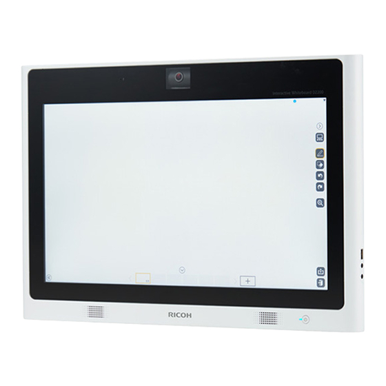
1. Product Information Product Overview Main Unit Name Control panel Microphone Camera Speaker Power indicator Power button USB port... -
Page 14: Control Panel
1. Product Information Name Audio output Audio input Control Panel Name Brightness control buttons Volume control buttons Mute button... -
Page 15: Back
Product Overview Back Name Camera direction adjustment lever Stand Ports... -
Page 16: Input/ Output Terminals
1. Product Information Input/ Output Terminals Name Power connector detachment prevention claw Power connector HDMI Output USB port Ethernet interface (10/100/1000 Mbps LAN port) HDMI Input DisplayPort Input VGA Input... -
Page 17: Machine Codes And Peripherals Configuration
Machine Codes and Peripherals Configuration Machine Codes and Peripherals Configuration Product List Main Unit Brand name Product code RICOH Interactive Whiteboard D2200 North America/Latin America: Y304-17 Europe/Asia: Y304-27 Option Brand name Product code Interactive Whiteboard Remote License Type Y401-17... -
Page 18: Specifications
1. Product Information Specifications See "Appendices" for details. -
Page 19: Installation
2. Installation Installation Requirements Operating Environment • Install in a location within the following environmental range. Item Environment Temperature 0 to 32°C (32 to 89.6°F) Humidity 10 to 80% (without condensation) Maximum altitude 2,500 m (8,202 feet) Power source 100-240 V AC, 50/60 Hz Operating frequency band 2402 –... -
Page 20: Wall Mounting Precautions
2. Installation 3. Right: 40 mm (1.6 inches) or more 4. Under: 40 mm (1.6 inches) or more Wall Mounting Precautions A VESA-compliant bracket is required to mount the main unit on a wall. • When mounting a VESA-compliant bracket, use the bracket that corresponds to 100 × 100 mm (3.94 ×... - Page 21 Installation Requirements...
-
Page 22: Accessory Check
2. Installation Accessory Check Accessories for the Main Unit Enclosed items Q'ty Note Power code VGA cable AC adapter Read this first Warranty sheet (NA Only) Option Brand name Note Interactive Whiteboard Remote License Type For using the real-time share function with remote locations... -
Page 23: Replacement And Adjustment
3. Replacement and Adjustment Notes on the Power Button Characteristics of the Power Button Power is supplied to the machine even when the power is turned OFF with the power button. The power button in this machine uses DC (direct current). Therefore, if the AC power cord is connected to an AC wall outlet, power is supplied to the main board, the operation unit and other modules even when the power is turned OFF. -
Page 24: Before Replacing Parts
3. Replacement and Adjustment Before Replacing Parts • Turn off the main power. • Remove the AC cord and the DC side of the AC adapter. This is because, when the AC adapter is connected, the discharge time of the AC adapter is added to the time it takes to remove the residual charge. -
Page 25: Special Tools
Special Tools Special Tools For system update and replacement, the following tools are required: Item Note USB flash drive For system update Nutdriver For removing hex screws on the terminal... -
Page 26: Parts Replacement
3. Replacement and Adjustment Parts Replacement Stand Cover Stand cover [A] Stand Stand cover (page... -
Page 27: Rear Cover
Parts Replacement Stand [A] Rear Cover • There is still residual charge inside the machine after you disconnect the AC adapter. Remove the AC adapter from the main machine and wait for 5 seconds before you remove the cover. - Page 28 3. Replacement and Adjustment Remove the screws. • Check the position of the hooks in the photo below before removing.
-
Page 29: Switch Board
Parts Replacement Rear cover [A] Switch Board Rear cover (page Switch board [A] Main Board Cover Rear cover (page... - Page 30 3. Replacement and Adjustment Remove the screws. • To avoid damaging the screws in the photo below, use a nut driver.
-
Page 31: Fan
Parts Replacement Main board cover [A] Main board cover (page... - Page 32 3. Replacement and Adjustment Fan [A] • When installing the fan, make sure that the label of the fan is at the outer side, and the harness is close to the connector. • If the fan is attached in the opposite direction, it may cause failure or problems.
-
Page 33: Main Board
Parts Replacement Main Board Main board cover (page Main board [A] Memory Main board cover (page Release the stoppers [A]. -
Page 34: Ssd
3. Replacement and Adjustment Memory [B] Main board cover (page Remove the screws. -
Page 35: Wireless Lan Board
Parts Replacement SSD [A] Wireless LAN Board Main board cover (page Wireless LAN board [A] Speakers Main board cover (page... -
Page 36: Camera
3. Replacement and Adjustment Speakers [A] Camera Main board cover (page Camera unit [A]... -
Page 37: Lcd Controller Board
Parts Replacement Camera cover [B] Camera [C] LCD Controller Board Rear cover (page... -
Page 38: Microphone
3. Replacement and Adjustment LCD Controller board [A] Microphone Main board cover (page Microphone [A] Power Board Rear cover (page... -
Page 39: Capture Board
Parts Replacement Power board [A] Capture Board Main board cover (page Capture board [A] Side IO Board Rear cover (page... -
Page 40: Display And Lcd Module
3. Replacement and Adjustment Side IO board [A] Display and LCD Module Main board (page Speaker (page Camera (page LCD controller board (page Power board (page Capture board (page Side IO board (page Display and LCD module [A]... -
Page 41: System Maintenance
Connect the USB flash drive to the D2200. Execute the system update for administrator setting application on the D2200. A list of files available to update appears. Select the target update file, and press [OK] to start the update process. -
Page 42: Export/Import Of Application Settings
4. System Maintenance Export/Import of Application Settings This machine can import/export the device setting information using a USB flash drive. Since the contents of the exported/imported file are encrypted, they cannot be checked. Items Subject to Export/Import You can back up the settings and recover the former settings with the backup file. The following items can be exported to a USB flash drive: Items Description... - Page 43 Export/Import of Application Settings Items Description • White board address • Auto shut-down time setting • Auto stand-by time setting • Remote white board image quality setting System Settings • Temporarily save settings • Save duration • USB flash drive setting •...
- Page 44 4. System Maintenance Item name Export Remarks E-mail transmitting server settings Available 1. For the SMTP server, the following items can be set. • Address • Port number • Default value: 25 • Encryption method • None (default) • StartTLS •...
-
Page 45: File Type
Export/Import of Application Settings File Type The ZIP file named "iwb-settings-YYYYMMDD-hhmmss.zip" is stored in the root directory in the USB flash drive. YYYYMMDD-hhmmss: Export execution date (local time) Export Procedure Insert a USB flash drive into the USB port of the main unit, and open [Export Device Configuration] in the administrator setting application. - Page 46 4. System Maintenance One of the following screens is displayed when export failed.
-
Page 47: Import Procedure
Export/Import of Application Settings Import Procedure Copy the exported data (ZIP file) to the root of the USB flash drive. Insert the USB flash drive into the USB port of the main unit, and open [Import Device Configuration] in the administrator setting application. - Page 48 4. System Maintenance When import is completed normally, a dialog to request rebooting is displayed, and then reboot the main unit according to the instructions. One of the following screens is displayed when import failed. If the [OK] button is clicked, it will return to the administrator setting application screen.
- Page 49 Export/Import of Application Settings...
-
Page 50: Service Mode
4. System Maintenance Service Mode Service Mode Outline The following functions are only for service. Item Contents Purpose of use Device Manager Settings Checks the hardware Condition check on the position operating state sensor, capture board, etc. Display Color Patterns Two or more color patterns Check for display abnormality in the are displayed on the screen. -
Page 51: How To Enter The Service Mode
Service Mode How to Enter the Service Mode Touch and hold the [Close] icon. Tap [Close]. Double-tap the [Settings] icon. Touch and hold [Version Information] for five seconds. - Page 52 4. System Maintenance Tap the [Search] icon. Tap the [ServiceSettings] icon. Enter the password for service "y300kb" in the dialog box and tap [OK]. The Service Setting Menu is displayed.
-
Page 53: Device Manager
Service Mode Device Manager Tap [Device Manager Settings] on the Service Settings Menu. The hardware operation confirmation screen shown below is displayed, on which the status of each device can be checked. Display Color Patterns Connect a USB keyboard to the USB terminal of the main unit. -
Page 54: Display Touch Keyboard
4. System Maintenance Tap [Display Color Patterns] on the Service Settings Menu. Change the color pattern, using the F1 to F7 keys on the USB keyboard. Press the ESC key to finish the display color pattern check. Display Touch Keyboard Tap [Display Touch Keyboard] on the Service Settings Menu. -
Page 55: Simple Can Bus
Service Mode Simple CAN Bus Tap [Simple CAN Bus] on the Service Settings Menu. Make sure that you can draw a line with your finger. Initialize Administrator Password Tap [Initialize Administrator Password] on the Service Settings Menu. Tap [Initialize]. -
Page 56: Windows Activation
4. System Maintenance Windows Activation License Activation via the Internet Tap [Window Activation] on the Service Settings Menu. Tap [Activate]. Tap [Close] to finish the activation. -
Page 57: License Activation By Phone
Service Mode Tap [Close]. If activation failed, the screen below is displayed. If error code 80072EE7 is displayed, check the connection with the Internet and perform license activation again. For any error code other than above, refer the URL below to take the appropriate countermeasures. - Page 58 4. System Maintenance Tap [Activate by Phone]. Select the nearest location, and then tap [Next]. Call the phone number displayed. Enter the installation ID listed on the screen into phone’s keypad. • Write down the confirmation ID given by the phone guidance.
- Page 59 Service Mode Enter the confirmation ID on the screen, and then click [Next]. Tap [Close] to finish the activation. Tap [Close].
- Page 60 4. System Maintenance If activation failed, the screen below is displayed. Enter the confirmation number again.
-
Page 61: Troubleshooting
5. Troubleshooting Error Messages Error Messages during the System Startup Message Error Code Cause Solution • Quickly press and release the power button on the front of the display. Instead of pressing the When the machine power button normally, one shuts down, press of the following actions was the power button... -
Page 62: Error Messages Related To Drawing Strokes
5. Troubleshooting Error Messages Related to Drawing Strokes Message Error Code Cause Solution • Delete unnecessary The number of handwritten pages containing entries exceeds the limit. strokes. 1004-1005 Page [xxx] and after will • Delete unnecessary be imported as images. strokes. -
Page 63: Error Messages Related To Sharing The Screen
Error Messages Error Messages Related to Sharing the Screen Message Error Code Cause Solution • Update the system. For details about Cannot connect because how to update the the software version is The version of the host system, refer to the different. -
Page 64: Error Messages When Saving A Pdf File
5. Troubleshooting Message Error Code Cause Solution • The network cable is Check the network status not connected. and re-open the session. Cannot continue remote • The IP address is not For details about how to whiteboard because of a set. - Page 65 Error Messages Message Error Code Cause Solution Cannot save temporarily Ask the whiteboard’s saved files. Insufficient free The temporarily saved file administrators to delete space in the temporary 1012-2009 size reaches the upper limit some temporarily saved save folder. (10GB). files through Contact your “Administrator Settings”.
- Page 66 5. Troubleshooting Message Error Code Cause Solution • Check whether the network cable is connected, or the cable is broken. • The network cable is • Access not connected, or the Administrator cable is broken. Settings and check • There is an error in the the Network Failed to send the email.
- Page 67 Error Messages Message Error Code Cause Solution The meeting code is Enter the meeting code incorrect. Incorrect meeting code is that has been entered entered. Enter the correct meeting when saving temporarily. code. • Disconnecting the USB • Allocate sufficient flash drive during Cannot save.
-
Page 68: Error Messages Related To Configuration
5. Troubleshooting Error Messages Related to Configuration Message Error Code Cause Solution Check whether any of the following apply: • The e-mail address is left blank. • More than 64 characters are used Cannot import because for the local block the email address format is of the email The format of the e-mail... - Page 69 Error Messages Message Error Code Cause Solution Check whether any of the following apply: The IP address is left blank. The IP address is not composed of four parts, each separated by a period, which contain Cannot import because three or fewer single-byte the IP address format is The file to be imported digits.
- Page 70 5. Troubleshooting Message Error Code Cause Solution Instead of pressing the Open “Administrator power button normally, one Settings” and reconfigure of the following actions was the machine settings. For Returned to factory performed to force the details about defaults. Make the settings machine to shut down the “Administrator Settings”, again on administrator...
-
Page 71: Error Messages Related To Web Pages
Error Messages Message Error Code Cause Solution 1. IC card which cannot 1. Touch using an be authenticated has authenticated IC been touched. card. 2. Cannot access the 2. Check the network server through the access. Cannot login whiteboard network. 3. -
Page 72: Error Messages When Using The Device As A Monitor
5. Troubleshooting Message Error Code Cause Solution • The specified meeting • Reboot the video code is incorrect. conferencing device. • There is no temporarily saved file associated • Reconnect the USB with the specified cable for the video meeting code. conference device and your computer. - Page 73 Error Messages Message Error Code Cause Solution Cannot display because of copyright protected (HDCP) contents. Cannot display copyright protected contents on HDMI Input 1. Connect to 1002-2007 the external input terminal: HDMI Input 2 and click [Enter/Input]. *Cannot use whiteboard The attempt to open function on HDMI Input 2.
-
Page 74: Error Messages Related To File Reading
5. Troubleshooting Error Messages Related to File Reading Message Error Code Cause Solution Cannot add all the pages. Unable to add all the Some pages cannot be pages because the page added because the page Select [Yes] to read, or limit ([xxx] pages) has 1004-1001 count of the PDF exceeds... - Page 75 Error Messages Message Error Code Cause Solution Cannot import the file. • The file format is not The following are possible PPT. (ex.: A file that causes. merely changed the Make sure that the PPT file - The file format is not file extension to .ppt can open in your PC, and PowerPoint.
- Page 76 5. Troubleshooting Message Error Code Cause Solution • Cannot access the • Make sure that the shared folder through whiteboard connects the network. to the network, an IP • The network is busy. address is set properly, and other Cannot access the shared •...
- Page 77 Error Messages Message Error Code Cause Solution Cannot import all the Remote participating If remote participating pages because an whiteboards in multiple whiteboards import a large unexpected error has locations tried to import a file, import the file in one occurred while importing large size file at the same location at a time.
-
Page 78: Error Messages Related To Remote Whiteboard Sharing
5. Troubleshooting Message Error Code Cause Solution The sent PDF file is that the following conditions are true: • The PDF file is not from version 1.3 to version 1.7. • The page size exceeds the limit (A0). • A password is set on The PDF file: Cannot import this file to open the the file, only versions 1.3 to... - Page 79 Error Messages Message Error Code Cause Solution Remote whiteboard is not The remote whiteboard is Start the remote started on the whiteboard's not started. whiteboard. main unit. Cannot start remote whiteboard. The following are possible • The network cable is Check the network status causes.
- Page 80 5. Troubleshooting Message Error Code Cause Solution The whiteboard has recognized that a UCS connects to the whiteboard • Reboot the UCS. through an USB cable, but • Connect the USB the any of the following cable again. occurs: • If these problems •...
-
Page 81: Error Messages For Ricoh Interactive Whiteboard Client
Error Messages Error Messages for RICOH Interactive Whiteboard Client Message Error Code Cause Solution • Enter the correct IP address or host name. • Contact the administrator to check that the • The entered IP address following settings is incorrect. - Page 82 The maximum number of remote whiteboards Disconnect the iPad that Reach the connection limit connected to RICOH is connected to a remote Interactive Whiteboard whiteboard Client has been reached. The IWB Client’s version is Update the version of Update Application old and cannot connect.
- Page 83 Error Messages Message Error Code Cause Solution The entered IP address is Enter the correct IP Cannot connect incorrect. address or host name. The entered passcode is Enter the correct The passcode is wrong incorrect. passcode. 1. The DNS server is not 1.
- Page 84 5. Troubleshooting Message Error Code Cause Solution 1. The terminal is not 1. Make sure the connected to the network status of the network. iPad, and move to the radio range of 2. Cannot participate in the access point that the remote whiteboard can be connected.
-
Page 85: Error Messages Related To Network
Error Messages Error Messages Related to Network Message Error Code Cause Solution Cannot continue sending the email because of a communication error. • Connect the • The network cable is The following are possible network cable to the not connected. causes. - Page 86 5. Troubleshooting Message Error Code Cause Solution Go to network settings in The hostname cannot be Enter the correct administrator settings to set 1001-2510 resolved from the IP hostname. the DNS server. address. Cannot access the shared folder. The following are possible causes.
- Page 87 Error Messages Message Error Code Cause Solution • The shared folder does not work properly. • The server that provides folder sharing does not connect to the network properly. • The protocol providing shared access is not Cannot access the shared CIFS (SMB).
-
Page 88: Error Messages Related To Ricoh E-Sharing Box
5. Troubleshooting Error Messages Related to RICOH e-Sharing Box Message Error Code Cause Solution Cannot import the file. The PDF file version you are Change the import PDF PDF files from version 1.3 to 1004-2009 importing to the whiteboard file version from 1.3 to 1.7 can be imported. -
Page 89: Error Messages Related To Remote Desktop Software
Error Messages Error Messages Related to Remote Desktop Software Message Error Code Cause Solution Cannot start remote PC 2001-00001 The wrong passcode is Enter the correct operation. entered. passcode that is displayed on the top of The passcode is wrong. the whiteboard's main Check the passcode that is unit. - Page 90 5. Troubleshooting Message Error Code Cause Solution Cannot start remote PC 2001-10051 • This PC is not • Check if this PC is operation. connected to the connected to the 2001-10065 network. network, and set Cannot access the network. correct settings. Check the network settings •...
-
Page 91: Other Error Messages
Error Messages Message Error Code Cause Solution Cannot start remote PC 2001-11004 • The whiteboard IP • Enter the IP address operation. address you are and connect to the 2001-10061 connecting is whiteboard which The following are possible wrong. has been started or causes. - Page 92 5. Troubleshooting Message Error Code Cause Solution Cannot import the shared • The number of data folder list. items for folder sharing Check the contents of the is incorrect. Modify the contents of the file. The last allowed • Each data item of folder sharing setting file.
- Page 93 USB cable. • If these problems There is a problem in the persist, retrieve the Cannot start RICOH UCS USB connection between log/settings. (Logs screen sharing. the video conferencing and system settings device and the computer.
- Page 94 • The synchronization whiteboard. change the IP source device does • RICOH Whiteboard is address. not respond specified as the source • Update the system • The synchronization device, but it does not...
- Page 95 -Cannot access the network waiting for a while. Please try again later. If there is no improvement contact your administrator. • IWB: [RICOH UCS] UCS account initial Perform UCS account Initial registration is registration is not initial registration on the required performed.
- Page 96 Cause Solution The other unit has been Perform the UCS function logged into using the same again. • IWB: [RICOH UCS] contact ID that was used to (Select UCS on the Logged out log into this unit. IWB/UCS switch screen or restart the unit.)
- Page 97 Error Messages Message Error Code Cause Solution 1. The synchronous 1. Change the function on device administrator configuration is ON password of the and the administrator synchronized IWB, password of the after changing the synchronization administrator source is the factory password of the default password.
- Page 98 5. Troubleshooting Message Error Code Cause Solution 1. The synchronization 1. Turn the power on source device has the synchronization been turned the power source device or off or it is not IWB. change the IP address. 2. The synchronization source is RICHO IWB;...
-
Page 99: Troubleshooting
Troubleshooting Troubleshooting • For any problems on options, refer to “Option”. Defects in the Display Problem Cause Solution Power is not supplied, and the • AC adapter or power • Connect the power cord. power indicator does not light. cord is not connected. •... -
Page 100: Defects In The Capture Board
After the power is turned ON, a Main board defective Change the main board. (The SSD beep is output while the Ricoh in the defective controller box can logo screen is displayed or the be used with the new main board.) screen freezes up and goes black. - Page 101 Problem Cause Solution After the power is turned on, the Hardware defective Ricoh logo screen is displayed but freezes up. After the power is turned ON, the Ricoh logo screen is displayed then the screen freezes up and goes black.
-
Page 102: Errors At Start-Up
5. Troubleshooting Errors at Start-Up The following are the causes and the solutions when an error is displayed after the start-up screen is displayed. Error display Cause Solution Primary Boot Device Not Found SSD is not recognized. • Check the SSD connector •... -
Page 103: Iwb Network Environment Check Tool
IWB Network Environment Check Tool IWB Network Environment Check Tool Outline • Application for Windows for checking the state of a network connection • The tool is started with two computers connected to the same LAN as the device (IWB/remote viewer), the IP address of the remote location is input, and diagnosis is started. -
Page 104: How To Use The Tool
5. Troubleshooting How to Use the Tool Beforehand This tool diagnoses the network environment between two computers. Decide in advance which is to be the server or the client. Operation on the Server Side When the Caution dialog is displayed, press [OK]. - Page 105 IWB Network Environment Check Tool Start up the IWB Network Environment Check Tool. When the Starting screen is displayed, press [Next]. When the Site selection picture is displayed, click [Server Computer] (originating side).
- Page 106 5. Troubleshooting When the server's (originating side) IP address is displayed, inform the IP address to the partner (client computer side). The partner (client computer side) inputs the server's (originating side) IP address, and presses [verification start]. Verification is started.
- Page 107 IWB Network Environment Check Tool The result screen is displayed. Push [Exit]. If needed, press [Show Detailed Logs], and obtain information by pressing [Save a Diagnostic Report]. Operation on the Client Side Start up the network diagnostic tool. When the Starting screen is displayed, press [Next].
- Page 108 5. Troubleshooting When the Site selection picture is displayed, click [Client Computer] (receiving side). Input the IP address informed from the server side, and press [Start Diagnosis].
- Page 109 IWB Network Environment Check Tool Verification is started. The result screen is displayed. Push [Exit]. If needed, press [Show Detailed Logs], and obtain information by pressing [Save a Diagnostic Report].
- Page 110 MEMO...
- Page 111 RICOH Interactive Whiteboard D2200 Machine Code: Y304 Appendices...
- Page 113 TABLE OF CONTENTS 1. Appendices:Specifications Specifications..............................3 General Specifications...........................3 Power Consumption According to Mode.....................5 Start and Return time..........................5 Supported Video Input Signals........................6...
-
Page 115: Appendices:specifications
1. Appendices:Specifications Specifications General Specifications Item Description Display type IPS liquid crystal system Max. resolution 1920 x 1080 dots Max. colors About 16M 700K colors (8 bits for each of R, G, and B) Pixel pitch (Horizontal x Vertical) 0.2475(H) x 0.2475(V) (mm) Backlight LED system Supported scanning frequency... - Page 116 1. Appendices:Specifications Item Description Input/Output terminals Video input terminals: • Analog Mini D-SUB 15pin • Display port x 1 (HDCP is not supported) • HDMI x 1 (HDCP is not supported) Audio input terminals: • Microphone x 1 Video output terminals: •...
-
Page 117: Power Consumption According To Mode
Specifications Power Consumption According to Mode Start and Return time Power consumption according to mode • Main power supply OFF: Less than 1 W • Main power supply ON (at the operation): 65W or less • Main power supply ON (standby (display OFF)): 15W or less •... -
Page 118: Supported Video Input Signals
1. Appendices:Specifications * After turning OFF, wait for about 10 seconds before pressing the power button. Return time from standby condition: • 5 seconds Supported Video Input Signals Supported input signal resolution for the Capture Input Capture Input Freque Signal format Resolution ncy(Hz Display Port... - Page 119 Specifications Capture Input Freque Signal format Resolution ncy(Hz Display Port HDMI input VGA input input VESA DMT 720 x 400 VESA GTF 800 x 600 VESA DMT 800 x 600 VESA CVT 800 x 600 VESA GTF 800 x 600 VESA DMT 800 x 600 VESA GTF...
- Page 120 1. Appendices:Specifications Capture Input Freque Signal format Resolution ncy(Hz Display Port HDMI input VGA input input VESA DMT 1024 x 768 VESA CVT 1024 x 768 VESA DMT 1024 x 768 VESA CVT 1152 x 864 VESA GTF 1152 x 864 VESA CVT 1152 x 864 VESA GTF...
- Page 121 Specifications Capture Input Freque Signal format Resolution ncy(Hz Display Port HDMI input VGA input input VESA GTF 1280 x 800 VESA DMT/CVT 1280 x 800 60(RB) VESA DMT/CVT 1280 x 800 VESA GTF 1280 x 800 VESA DMT/CVT 1280 x 800 VESA DMT/CVT 1280 x 800 VESA GTF...
- Page 122 1. Appendices:Specifications Capture Input Freque Signal format Resolution ncy(Hz Display Port HDMI input VGA input input VESA GTF 1360 x 768 VESA DMT 1360 x 768 VESA GTF 1366 x 768 VESA DMT 1366 x 768 60(RB) VESA DMT 1366 x 768 VESA GTF 1400 x 1050 VESA DMT/CVT...
- Page 123 Specifications Capture Input Freque Signal format Resolution ncy(Hz Display Port HDMI input VGA input input VESA DMT 1600 x 1200 VESA GTF 1680 x 1050 VESA DMT/CVT 1680 x 1050 60(RB) VESA DMT/CVT 1680 x 1050 VESA DMT 1920 x 1080 VESA DMT/CVT 1920 x 1200 60(RB)
- Page 124 MEMO...
Need help?
Do you have a question about the D2200 and is the answer not in the manual?
Questions and answers