Table of Contents
Advertisement
Advertisement
Table of Contents

Related Manuals for HARVEY C14


Summary of Contents for HARVEY C14
-
Page 3: Table Of Contents
CONTENTS 1. Safety------------------------------------------------------------------------------------------------------ 1 1.1 General Machine Safety.----------------------------------------------------------------------------- 1 1.2 Band Saw Safety.-------------------------------------------------------------------------------------- 1 2. Feature Identification-------------------------------------------------------------------------------- 2 3. Specifications------------------------------------------------------------------------------------------ 3 4. Unpacking and Setup-------------------------------------------------------------------------------- 4 4.1 Unpacking--------------------------------------------------------------------------------------------- -- 4 4.2 Checking Contents ----------------------------------------------------------------------------------- 4 4.3 Power Supply------------------------------------------------------------------------------------------- 5 4.4 Grounding----------------------------------------------------------------------------------------------- 5 4.5 Extension Cords--------------------------------------------------------------------------------------- 5 4.6 Dust Collection----------------------------------------------------------------------------------------- 5 5. -
Page 4: Safety
1. Safety 1.1 General Machine Safety 1. For your own safety, read the user manual before operating the band saw. 2. This machine must be properly grounded to help prevent electrical shock and possible fatal injury. 3. Form a habit of checking to see that the keys and the adjusting wrenches are removed from the machine before turning it on. -
Page 5: Feature Identification
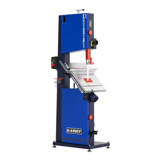
2. Feature Identification Fig.1 Upper Wheel Brake Pedal Upper Door Blade Tension Adjustment Hand Wheel Switch Panel Guide Post Locking Handle Tool Storage Hooks Rip Fence Brush Kerf lock handle Lower Door Upper Dust Port Motor Pulley Bottom screw Lower Wheel Tracking Knob Window Blade Tension Level... -
Page 6: Specifications
3. Specifications Model Power 2.2 kW 3 HP Rated Voltage 230 V Phase 1-Ph Frequency 50 Hz 60 Hz Full-Load Current 12.8 A Wheel Dia. 350 mm 14″ Blade Length 3175 mm 125 ″ Blade Width 3-25 mm 1/8 - 1″ Speed of Saw Blade 1050 m/min Max. -
Page 7: Unpacking And Setup
4. Unpacking and Setup The machine is shipped completely in one carton. 4.1 Unpacking Remove all of the contents from the shipping carton. Do not discard any shipping material until the band saw is fully assembled and running satisfactorily. 4.2 Checking Contents Inspect the contents for shipping damage. -
Page 8: Power Supply
4.3 Power Supply Electrical connections must be made by a qualified electrician in compliance with all relevant codes. This machine must be properly grounded to help prevent electrical shock and possible fatal injury. The band saw is factory wired for 230 volts and its operating amp rating is 10 A. -
Page 9: Assembly
5. Assembly The band saw is partially assembled. The following assembly must be completed before operation. 5.1 Stand Pad (Figure 3.) To be safe, we have mounted the band saw to the pallet for shipment. You must remove the pallet mounting bolts, screw in the stand pads (A) from the bottom of the band saw and tighten the nut (B) from the top. -
Page 10: Spring Assembly
5.3 Spring Assembly (Figure 5.) 1. Rotate the hand wheel (A) to tilt the table to 45°. 2. Attached the spring (B) to the mounting bracket on the bottom of the work table (C) and the back of the frame (D). 3. -
Page 11: Blade
5.6 Blade Refer to Figure 8. 1. Remove the table insert (A), loosen the locking handle (B) and remove it from the work table. 2. Release the blade tension lever (C) and then open the upper and lower doors. 3. Slide the blade (D) through the split on the table (E) and the frame (F). 4. -
Page 12: Adjustment
6. Adjustment 6.1 Blade 6.1.1 Blade Tension Refer to Figure 8. 1. Disconnect the machine from the power source. 2. Back off the upper and lower blade guides to eliminate any contact with the blade. 3. Tighten the blade by the blade tension lever (C). 4. - Page 13 6.1.3 Blade Tracking After proper tensioning, the blade must be tracked. Tracking refers to the position of the blade on the wheels while the machine is in operation. Tracking should be checked periodically, and is mandatory after every blade change. Blade tracking is done by hand with the machine disconnected from the power source.
-
Page 14: Blade Guide
6.2 Blade Guide The blade guides should be set so that contact between the blade and the guides will occur only when the blade is under pressure from a workpiece. To adjust the upper bearing guides for proper blade control, proceed as follows: Fig. - Page 15 6.2.2 Lower Blade Guide Refer to Figure 11. 1. Disconnect the machine from the power source. 2. Open the lower door and uninstall the lower blade guard by loosening the guard locking knob. 3. Adjust the lower guide and thrust bearings below the table, using the similar procedure as for the upper guides.
- Page 16 Fig. 12 Refer to Figure 12. 1. Disconnect the machine from the power source. 2. Fully tension the blade. 3. Lower the upper blade guide assembly and make sure it is properly adjusted. 4. Loosen the guide post locking handle (A) and raise the guide post to the highest position.
-
Page 17: Work Table
6.3 Work Table 6.3.1 Table Tilt (Refer to Figure 13.) 1. Disconnect the machine from the power source. 2. Loosen the table tilt locking handle (A). 3. To tilt the table right, rotate the table tilt hand wheel (B) to tilt the table up to 45°. 4. - Page 18 6.3.3 Setting the Table Parallel to the Blade Refer to Figure 14. 1. Disconnect the band saw from the power source. 2. The blade should be fully tensioned and properly tracked. 3. Place a long straightedge ruler flush against the blade, making sure it contacts both the front and back of the blade.
-
Page 19: Fence
6.4 Fence 6.4.1 Fence Plate Positions (Refer to Figure 15.) 1. Loosen the fence plate locking screws (E) on the left side of the fence guide (B), until the lock bar (C) protrudes enough to slide the aluminum fence plate out of the fence guide (B). - Page 20 6.4.3 Setting the Cursor Zero Position The fence must be set so that the cursor reads zero at the line of the blade. The fence plate must be installed on the fence body in the vertical position, and the blade must be installed and fully tensioned.
-
Page 21: Belt Tension And Replacement
6.5 Belt Tension and Replacement The belt tension should be occasionally checked when the band saw is new, as a new belt may stretch slightly during the breaking-in process. If the belt becomes worn, cracked, frayed or glazed, it should be replaced. Please follow the steps to adjust the belt tension or belt replacement: Fig. -
Page 22: Operation
7. Operation 7.1 Switch Do not start the band saw until all assembly and adjustments have been completed. Refer to figure 17. Fig. 17 Press the green button (A) to start the band saw. Press the red stop button (B) to stop the band saw. 7.2 Brake Pedal When the stop button is used to stop the band saw, the blade will coast slowly to a stop. -
Page 23: Application
8. Application The following section contains basic information, and is not intended to cover all possible applications or techniques using the band saw. 1. Make sure the blade is adjusted correctly for tension and tracking, and the upper and lower blade guide are set in proper relation to the blade. 2. -
Page 24: Curve Cutting
8.4 Curve Cutting When cutting curves, simultaneously feed and turn the stock carefully so that the blade follows the layout line without twisting. Always make short cuts first, then proceed to the longer cuts. Relief cuts will also reduce the chance that the blade will be pinched or twisted. Relief cuts are cuts made through the waste portion of the workpiece and are stopped at the layout line. -
Page 25: Maintenance
9. Maintenance Before doing maintenance on the machine, disconnect it from the electrical supply by pulling out the plug or switching off the main switch! Failure to comply may cause serious injury. 9.1 Lubrication Periodically apply a light, non-hardening grease to the rack and pinion system of the guide post. -
Page 26: Trouble Shooting
10. Trouble shooting Trouble Probable Cause Remedy Locking handle not tight. Tighten locking handle. Table tilt does not hold Trunnion locking mechanism is broken position under load. Replace trunnion locking mechanism. or worn. Trunnion not lubricated. Lubricate trunnion. Table will not tilt. Disassemble and replace jammed Trunnion jammed. - Page 27 Refer to blade selection chart; use Blade pitch too coarse. finer pitch blade. Check guide bearings for correct Guide bearings not properly position and signs of wear. Adjust or supporting blade. replace as needed. Blade tensioned too tightly. Reduce tension. Have blade annealed, or eliminate Blade overheated during welding.
-
Page 28: Exploded View And Parts List
11. Exploded View and Parts List Frame Assembly Exploded View... - Page 29 Frame Assembly Parts List Description Description Hex Socket Cap Screw M6×12 Lock Nut M8 Hinge washer 8 Cap Screw M5×12 Dust Guard Upper Door Flat washer 6 Shockproof soft article Spring washer 6 Sight glass Cap Screw M6×16 Flat washer 5 Lock Nut M12 Lock Nut M5 Anchor bolt M12×60...
- Page 30 Wheels and Blade Tension Level Assembly Exploded View...
- Page 31 Wheels and Blade Tension Level Assembly Parts List Description Description Knob Shaft Handle Lock Nut M10 Adjusting Nut Lock Nut M12 Knob M8×35 Square Screw Flat washer 12 Rubber Belt Spring washer 12 Square Shaft Lock Nut 12 Guide Bar Cap Screw M8×30 Shaft Bracket Spring washer 8...
- Page 32 Table, Fence and Trunnion Assembly Exploded View...
- Page 33 Table, Fence and Trunnion Assembly Parts List Description Description Cap Screw M8×25 Locking Screw Spring washer 8 Handle M10×20 Hexagonal rod bolt Gas spring bracket 1 Sliding Block Cap Screw M6×16 Lock Block Pin 6×22 Rail Bar Gas spring Bolt R Pin 1.5×6.5×23 Lock Nut M8 Lock Nut M6...
- Page 34 Upper Blade Guide and Brake Pedal Assembly Exploded View...
- Page 35 Upper Blade Guide and Brake Pedal Assembly Parts List Description Description Cap Screw M5×10 Flat washer 8 Rack Cap Screw M8×30 Cap Screw M8×16 Brake rubber block Spring washer 8 Screw Flat washer 8 Brake rod cap nut M4 Spring guard plate Lock Nut M8 shield...
- Page 36 Motor and Lower Blade Guide Assembly Exploded View...
- Page 37 Motor and Lower Blade Guide Assembly Parts List Description Description Cable connector PG13.5 Set Screw M8×10 Motor Label Bracket Motor 230V 60Hz 3HP Lock Knob Flat washer 5 Hex Cap Bolt M10×25 Spring washer 5 Spring washer 10 Cap Screw M5×16 Flat washer 10 Upper Guide Bracket Flange...
- Page 38 Electric Assembly Exploded View...
- Page 39 Electric Assembly Parts List Description Description Main Switch Electrical box Brake line Cable connector PG9 Crimping Terminal 1.5 Sealing Strip Switch Bracket Bracket Cap Screw M5×12 Block Flat washer 5 Cross pan head screw ST2.9×6.5 Spring washer 5 Cross head screw ST2.9×9.5 Cap Screw M5×12 Ac contactor Cable sheath 0811...
Need help?
Do you have a question about the C14 and is the answer not in the manual?
Questions and answers