
Related Manuals for Cypress FM4 S6E2H Series


Summary of Contents for Cypress FM4 S6E2H Series
- Page 1 FM4 S6E2H-Series Starter Kit Guide Doc. No. 002-11387 Rev. ** Cypress Semiconductor 198 Champion Court San Jose, CA 95134-1709 Phone (USA): 800.858.1810 Phone (Intnl): +1 408.943.2600 www.cypress.com...
- Page 2 A critical component is any component of a device or system whose failure to perform can be reasonably expected to cause the failure of the device or system, or to affect its safety or effectiveness. Cypress is not liable, in whole or in part, and Company shall and hereby does release Cypress from any claim, damage, or other liability arising from or related to all Unintended Uses of Cypress products.
-
Page 3: Table Of Contents
Contents Introduction ................................. 4 Kit Contents ................................ 5 Board Details ..............................6 Jumper and Connector ............................8 Getting Started ..............................9 Additional Learning Resources ........................... 9 Technical Support ............................... 9 Acronyms................................10 Installation and Test Operation ..........................11 Install Software ..............................11 Uninstall Software ............................. -
Page 4: Introduction
Introduction Thank you for your interest in the FM4-120L-S6E2HG FM4 S6E2H-Series Starter Kit. The FM4 S6E2H-Series Starter Kit enables customers to evaluate and develop projects using the FM4 device family. Flexible MCU 4 (FM4) is a portfolio of high-performance ARM® Cortex®-M4 MCUs that includes hardware support for digital signal processing and floating-point operations, designed for safety-critical, industrial systems and home appliance applications. -
Page 5: Kit Contents
USB Standard-A to Micro-B cable Quick Start Guide Figure 1-1: Kit Contents Inspect the contents of the kit; if you find any part missing, contact your nearest Cypress sales office for help: www.cypress.com/support. FM4 S6E2H-Series Starter Kit Guide, Doc. No. 002-11387 Rev. **... -
Page 6: Board Details
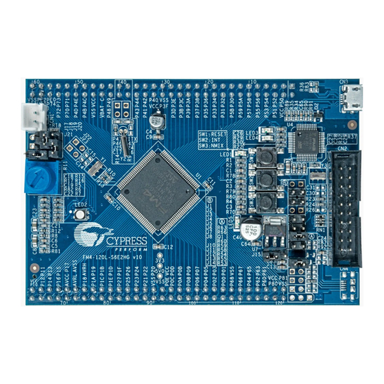
Introduction 1.2 Board Details Figure 1-2: FM4 S6E2H-Series Starter Kit Markup FM4 S6E2H-Series Starter Kit Guide, Doc. No. 002-11387 Rev. **... - Page 7 Introduction 1. Cypress FM4 MCU S6E2HG6A0J 2. Non-Maskable Interrupt pin (NMIX) switch (SW3) 3. User button (SW2) 4. Reset LED 5. Reset button 6. MB9AF312K Programmer and Debugger (CMSIS-DAP) 7. 20-pin JTAG interface (CN2) 8. VBUS selection jumper for CMSIS-DAP (J2) 9.
-
Page 8: Jumper And Connector
Introduction 1.3 Jumper and Connector Table 1-1: Connector Description Connector Description Battery connector 20-pin JTAG interface USB port of CMSIS-DAP SD card interface Table 1-2: Jumper Description Jumper Function Setting VBUS detection of CMSIS-DAP Open: For on-board voltage is 3.3V Used for VBUS detection function (pin Closed: For on-board voltage is 5.0V 60) of MB9AF312K on board... -
Page 9: Getting Started
The documents listed above can be accessed from the kit’s webpage at www.cypress.com/FM4-120L-S6E2HG. 1.6 Technical Support For assistance, visit Cypress Support or contact customer support at +1(800) 541-4736 Ext. 2 (in the USA) or +1(408) 943-2600 Ext. 2 (International). FM4 S6E2H-Series Starter Kit Guide, Doc. No. 002-11387 Rev. **... -
Page 10: Acronyms
Introduction 1.7 Acronyms Table 1-3. Acronyms Used in this Document Acronym Description Analog-to-Digital Converter CMSIS-DAP Debug Access Port GPIO General Purpose Input/Output Inter-Integrated Circuit Integrated Development Environment Low Drop Out (voltage regulator) Light-Emitting Diode Interuppt Red Green Blue JTAG Joint Test Action Group Multi Function Serial Peripheral Driver Library Serial Wire Debug... -
Page 11: Installation And Test Operation
2.1 Install Software Follow the steps below to install the FM4 S6E2H-Series Starter Kit software: Download the FM4 S6E2H-Series Starter Kit installer from the webpage www.cypress.com/FM4-120L-S6E2HG. The Kit software is available for download in three formats. FM4 S6E2H-Series Starter Kit Complete Setup: This installation package contains the files related to the kit, including the Documentation, Hardware, Firmware, Software tools and drivers. - Page 12 Installation and Test Operation Click Install FM4-120L-S6E2HG to start the kit installation, shown as Figure 2-1. Figure 2-1: Kit Installation Window Select the folder in which you want to install this package or use the default folder and click Next. Choose the Typical, Custom, or Complete installation type (select 'Typical' if you do not know which one to select) in the Product Installation Overview window, as shown in Figure...
- Page 13 Installation and Test Operation When you click Next, the FM4 S6E2H-Series Starter Kit installer automatically installs the required software, if it is not present on your PC. Following are the required software and driver: FM Universal Peripheral Driver Library (PDL) ...
-
Page 14: Uninstall Software
Go to Start > Control Panel > Programs and Features for Windows 7 or Add/Remove Programs for Windows XP; select the Uninstall button. Note: Uninstalling the Kit software will not remove the FM PDL 2.0 and FM4 S6E2H Series Starter Kit Example Projects from <User_Directory>. -
Page 15: Test Operation
LED (LED2) will alternately flash red, green, and blue. If not already launched, then launch the Serial Port Viewer from the start menu under All Programs > Cypress > Serial Port Viewer. FM4 S6E2H-Series Starter Kit Guide, Doc. No. 002-11387 Rev. **... - Page 16 Click on the Serial Port Viewer icon in the task bar and select the FM-Link/CMSIS-DAP Cypress FM Communications Port. Figure 2-6: FM-Link/CMSIS-DAP Cypress FM Communications Port Select the baud rate 115200, and click the Disconnect button to connect the board.
- Page 17 Installation and Test Operation For example, key in 1 to test the Red LED. Figure 2-9: Red LED Test-1 Press the Enter key to complete the Red LED test. The terminal window will display TESTED. Figure 2-10: Red LED Test-2 FM4 S6E2H-Series Starter Kit Guide, Doc.
- Page 18 Installation and Test Operation 2.3.2 Test Procedure Explanation This section explains the test procedure. This test procedure is based on the Serial Port Viewer. The user has to key-in the test procedure number displayed on the menu to run the test procedures and then press the Enter key on the PC to complete the test.
- Page 19 Installation and Test Operation Blue LED (RGB LED) Test: This procedure will test whether blue LED works normally. Key in 3 to run the test procedure and the blue LED will blink. Then press the Enter key on the PC to complete the test. TESTED will be displayed as shown in Figure 2-13.
- Page 20 Installation and Test Operation SW3 User Key Test: This procedure is to test switch SW3. Key in 5, and then press SW3 on the starter board. The RGB LED (LED2) will glow green while SW3 is held down. Release SW3 and press Enter to complete the test. It will display OK. Figure 2-15: SW3 User Key Test ...
- Page 21 Installation and Test Operation SD Card Test: This procedure tests the SD Card. Key in 7 and press the Enter key. If an SD Card is found in the SD card slot (CN5) and read successfully, the console will display OK.
-
Page 22: Hardware
3.1 System Block Diagram Figure 3-1 shows the block diagram of the FM4 S6E2H-Series Starter Kit. Figure 3-1: System Block Diagram 3.2 Hardware Features Cypress FM4 S6E2HG MCU On-board ICE (CMSIS-DAP compatible) SD card interface All pins interface ... -
Page 23: Hardware Details
Hardware Reset button 20-pin JTAG interface Selectable on-board voltage (3.3 V or 5.0 V) 3.3 Hardware Details 3.3.1 FM4 Series MCU The FM4 S6E2HG MCU is a family of highly integrated 32-bit microcontrollers dedicated for high performance embedded controllers at competitive price. This series is based on the ARM®... - Page 24 Hardware 3.3.3 SD Card Interface CN5 is an SD card interface connected with the SDIO macro of the S6E2HG device. This SD card interface supports full function of the SDIO including data transmission, card detection and write protection. Figure 3-2: SD Card Circuit SD Card The pin arrangement of the SD card is shown in Figure...
- Page 25 Hardware Table 3-3 shows the signals of the SD card interface. Table 3-3: Signals of SD Card Interface Pin No. Pin Name Type Description DAT2 Data DAT3 Data Data Card detect VSS1 power Power supply ground power Power supply Clock VSS2 power Power supply ground...
- Page 26 Hardware 3.3.5 JTAG The FM4 S6E2H-Series Starter Kit provides an interface, CN2, to connect an external programmer for programming the FM4 S6E2HG MCU or for connecting a third-party debugging tool. CN2 is a standard ARM 0.1’’ 10*2-pin Cortex debug connector. Figure 3-5: 10-pin JTAG I/F JTAG 3.3.6 Potentiometer...
- Page 27 Hardware 3.3.7 Expansion Port The FM4 S6E2H-Series Starter Kit provides two sets of expansion ports which route all the MCU pins. The user can access all pins of the S6E2HG device from these ports. Figure 3-7 shows the details. Figure 3-7: Expansion Port FM4 S6E2H-Series Starter Kit Guide, Doc.
-
Page 28: Software Development
Software Development This chapter provides information about the available software resources supporting the S6E2HG device and FM4 S6E2H-Series Starter kit. 4.1 Tool Options The FM4 S6E2H-Series is supported by several third party tools/IDEs, and the user can choose their preferred tool for development. Any one of below listed IDEs can used for opening and building the example projects packaged with this kit: ... - Page 29 Software Development Click File > Open > Workspace and select the workspace file s6e2hg_adc.eww from <User_Directory>:\ FM4 S6E2H-Series Starter Kit_Ver01 \Firmware\Demo Projects\s6e2hg_adc\IAR FM4 S6E2H-Series Starter Kit Guide, Doc. No. 002-11387 Rev. **...
- Page 30 Software Development Click Project > Rebuild All to build the project. Make sure the jumpers on the FM4 S6E2H-Series Starter board are placed according to Table 4-1. Table 4-1: Debugging Jumper Settings Jumper Position Description Open Sets MB9AF312K to 3.3V. Open Sets MB9AF312K (CMSIS-DAP) in run mode.
- Page 31 Software Development Click the Run icon to run the program once it is downloaded successfully. Refer to the Example Projects section for more details on example projects. Click the Stop icon to stop the program. For more information about the IAR Embedded Workbench IDE, please click Help from within the tool.
- Page 32 Software Development Click the Build icon to build this project. Make sure the jumpers on the FM4 S6E2HG-Series Starter board are placed according to Table 4-2. Table 4-2: Debugging Jumper Settings Jumper Position Description Open Sets MB9AF312K to 3.3V. Open Sets MB9AF312K (CMSIS-DAP) in run mode.
-
Page 33: Example Projects
Software Development 4.2 Example Projects The FM4 S6E2H-Series Starter Kit includes twelve example projects to help the user get a quick start with the S6E2HG device. The example projects are located in this directory: <User_Directory>:\FM4 S6E2H-Series Starter Kit_Ver01\Firmware \Demo Projects These examples listed in the Table 4-3 are based on the Peripheral Driver Library (PDL). - Page 34 Software Development Projects Title/Description Title: GPIO Description: This project demonstrates the GPIO operations of the S6E2HG device by s6e2hg_gpio driving an LED. Pin P38 sinks current from the green LED of the RGB LED (LED2). Pin P38 will output a pulse sequence to blink the LED continuously. Title: Multi-function Serial Interface Description: This project demonstrates the UART communication of the S6E2HG s6e2hg_mfs_uart...
- Page 35 Software Development 4.2.1 AD Converter 4.2.1.1 Project Description This project demonstrates the Analog-to-Digital conversion of the S6E2HG device. This example sets the ADC channel 18 in single conversion mode with interrupt enabled. ADC channel 18 is connected to a potentiometer. The conversion is started using a software trigger. When ADC conversion is completed, the interrupt callback function is called, it reads the result data and prints it to UART0.
- Page 36 Software Development Run the program and the ADC value will be displayed in the Serial Port Viewer window. Figure 4-2: ADC value Turn the potentiometer, the ADC values will change accordingly. 4.2.2 Direct Memory Access DMA) 4.2.2.1 Project Description This project demonstrates DMA operation of the S6E2HG device. The program configures DMA to move the data from au32SourceData (source array) to au32DestinationData (destination array), and then compares the content of the arrays to verify the data.
- Page 37 Software Development Open Watch1 window from View-> Watch. Add the arrays au32SourceData and au32DestinationData in Watch1 window. Run the program for a while (>10 seconds). Stop the program and check the arrays mentioned above. The Program Counter (PC) will stop at the routine as shown below which means the content of the arrays are the same. You can also verify the content of the arrays in the watch window.
- Page 38 Software Development Open Watch1 window from View->Watch Windows. Add the arrays au32SourceData and au32DestinationData in Watch1 window. Run the program for a while (>10 seconds). Stop the program and check the arrays mentioned above. The Program Counter (PC) will stop at the routine as shown below which means the content of the arrays are the same. You can also verify the content of the arrays in the watch window.
- Page 39 Software Development Open the project file in IAR Embedded Workbench from the following directory on your IAR project: <User_Directory>: \FM4 S6E2H-Series Starter Kit_Ver01\Firmware \Demo Projects\s6e2hg_flash\IAR\s6e2hg_flash.eww. Build the project and download the code into the S6E2HG device. Open the memory window from the View > Memory. Enter 0x00070000 in the Go to table and press the Enter Key on your PC.
- Page 40 Software Development Open the Memory1 window from the View > Memory Windows. Enter 0x00070000 in the Address table and press the Enter Key on your PC. Run the program for a while (>10 seconds). Stop the program and check the content of 0x00070000 in the flash. 4.2.4 UART Communication 4.2.4.1 Project Description This project demonstrates the UART communication of the S6E2HG device.
- Page 41 Software Development Figure 4-3: Select the Baud Rate Click the Toggle Outgoing Data Window button. Figure 4-4: Toggle the Outgoing Data Window Key in any characters in the Outgoing Data Window, the same characters will be echoed in the Input Data Window. Figure 4-5: Echo Test FM4 S6E2H-Series Starter Kit Guide, Doc.
- Page 42 Software Development 4.2.5 Sleep Mode 4.2.5.1 Project Description This project demonstrates the sleep mode operation of the S6E2HG device. The MCU will enter sleep mode after blinking the green LED 5 times. It can be woken up by pressing the SW3 key. After wakeup, the green LED will turn on.
-
Page 43: Flash Programming
Software Development If the watchdog is enabled, but not fed in time, the chip will reset, and the green LED will remain glowing. 4.2.6.2 Hardware Connection No specific hardware connections are required for this project. All connections are hardwired on the board. - Page 44 Observe that the Power LED (LED5) is glowing green. Launch the FLASH MCU Programmer from Windows Start Menu > All Programs > Cypress > FLASH MCU Programmer > FM0+ FM3 FM4 Select Target MCU as S6E2HG6G/E/F. Set Crystal Frequency to 4MHz.
- Page 45 Software Development 10. Enter the Virtual COM Port listed in the Ports of Windows Device Manager in COM box in the Customize setting window (This window appears when the Set Environment button is clicked). 11. Click on the Full Operation (D+E+B+P) button to start programming. 12.
- Page 46 Connect the USB cable to the CN3 port. Observe that the Power LED (LED5) is glowing green. Launch the FLASH USB DIRECT Programmer from Windows Start Menu > All Programs > Cypress > FLASH USB DIRECT Programmer > USBDirect Select the Target MCU as MB9AF312K.
- Page 47 Software Development Check the COM Port number in the Windows Device Manager. Enter the Virtual COM Port listed in the Ports of Device Manager in the COM box. 10. Click the Full Operation (D+E+B+P) button to start programming. FM4 S6E2H-Series Starter Kit Guide, Doc. No. 002-11387 Rev. **...
- Page 48 Software Development 11. Reset the CMSIS-DAP microcontroller by removing and reconnecting the USB cable, and click OK. 12. Click OK button in Erase and Program Complete window. Note: Please click on Help for any issues or errors encountered during programming. FM4 S6E2H-Series Starter Kit Guide, Doc.
-
Page 49: Appendix
680R LED_G VCC_MCU 10uF/16V 0.1uF 0.1uF 0.1uF 0.1uF 0.1uF 0.1uF LED-RGB PIN59_EX AN18 4MHz AVSS 100R AVRH VCC_MCU J24 Jumper2 Cypress PIN45 VWAKEUP 0.1uF 0.1uF PIN107 32.768KHz 1N4148 Author: VL VCC_MCU VCC_MCU PIN39_EX VBAT NC/12pF NC/12pF 12pF 12pF 220pF 100nF... - Page 50 SOT0_0 LED3 LED4 SIN1_1 MD0_DAP VCC_MCU 5V: CLOSED Y ELLOW USB-Micro_B Jumper3 Jumper2 VCC_MCU 3V3: OPEN Cypress D ebugger Tar get Connected Running Author: VL UHCONX_DAP Ti t l e MMS8550 FM4-120L-S6E2HG Si z e D ocum ent N um ber R ev CMSIS-DAP&JTAG...
- Page 51 SD_DAT1 SD_DAT1_0 SDSN09-A0-0015 PIN94 SD_W/P SD_W/P_0 PIN114 VCC_3V3 VCC_SD 180R@100M Cypress Author: VL Ti t l e FM4-120L-S6E2HG Si z e D ocum ent N um ber R ev Micro SD card interf ace D at e: Sheet Tuesday , August 25, 2015...
- Page 52 MADATA01_0 Flash_D1 MADATA00_0 Flash_D0 VCC_FLASH VCC_3V3 VCC_FLASH 180R@100M 0.1uF 0.1uF Cypress Author: VL Ti t l e FM4-120L-S6E2HG Si z e D ocum ent N um ber R ev NAND FLASH D at e: Sheet Tuesday , August 25, 2015...
- Page 53 SDRAM_BA1 MAD15_0 SDRAM_A3 MAD03_0 SDRAM_A10/AP MAD10_0 NOT M OUNTED VCC_3V3 VCC_SDRAM 180R@100M VCC_SDRAM VCC_SDRAM SDRAM_CS SDRAM_CKE Cypress 0.1uF 0.1uF 0.1uF 0.1uF 0.1uF 0.1uF 0.1uF SDRAM_CLK 10pF Author: VL Ti t l e FM4-120L-S6E2HG Si z e D ocum ent N um ber...
- Page 54 Jumper2 J14: Program Module: Closed Pin2 to Pin3 J11, J12: Function: CLOSED User Module: Closed Pin2 to Pin1 Host: OPEN Cypress Author: VL Ti t l e FM4-120L-S6E2HG Si z e D ocum ent N um ber R ev D at e:...
- Page 55 VCC_MCU 3V3: Closed Pin2 to Pin1 VCC_MCU 5V0: Closed Pin2 to Pin3 LED5 T POINT GREEN TEST PO I N T Cypress Author: VL Ti t l e FM4-120L-S6E2HG Si z e D ocum ent N um ber R ev...
-
Page 56: Bill Of Materials
Appendix Bill of Materials Item Reference Value Description Mfg part number 2.54mm, 2pin 2.54mm, 2pin,Wall AIMO 2285-0106ANGO01 connector 2.54mm,10*2pin IDC 2.54mm, 10*2pin,Wall AIMO 2285-0110ANGO01 connector 10118192-0001LF Micro USB type B 10118192-0001LF SDSN09-A0-0015 SD card interface PROCONN SDSN09-A0-0015 J2, J3, J5, J6, J7, J8, Pin header,1*2pin,dip 2.54mm, 2pin header AIMO... - Page 57 Appendix Item Reference Value Description Mfg part number R1, R78, R79, R80 Resister YAGEO RC0603FR-071KL R2, R4, R15, R16, R18, R20, R38, R39, Resister YAGEO RC0603FR-0710KL R40, R33, R51, R54, R84, R91 510R Resister YAGEO RC0603FR-07510RL 680R Resister YAGEO RC0603FR-07680RL 220R Resister YAGEO...
- Page 58 Appendix Item Reference Value Description Mfg part number Push- SW1, SW2, SW3 ELTSM-62KR-H-T/R button,6*6*5mm, Jinling ELTSM-62KR-H-T/R S6E2HG6G0A MCU,176LQFP,0.5m Cypress S6E2HG6G0A GV20000 GV20000 m pitch MCU,64LQFP,0.5mm MB9BF312K Cypress MB9BF312KPMC pitch LM1117IMPX- Regulator LM1117IMPX-3.3/NOPB 3.3/NOPB Ceramic Resonator, CSTCR4M00G15L99- Y1, Y3 Murata CSTCR4M00G15L99-*0 4M,1000ppm...
-
Page 59: Revision History
Revision History Document Revision History Document Title: FM4 S6E2H-Series Starter Kit Guide Document Number: 002-11387 Origin of Revision Issue Date Description of Change Number Change 5179566 03/24/2016 CCTA Initial revision. FM4 S6E2H-Series Starter Kit Guide, Doc. No. 002-11387 Rev. **...
Need help?
Do you have a question about the FM4 S6E2H Series and is the answer not in the manual?
Questions and answers