
Related Manuals for ADLINK Technology cPCI-6520


Summary of Contents for ADLINK Technology cPCI-6520
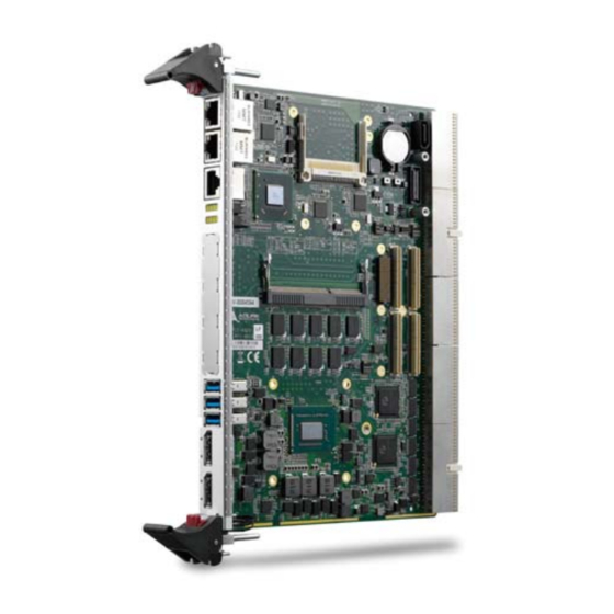
- Page 1 6U CompactPCI® 3rd Generation Intel® Core™ i7 Processor Blade User’s Manual Manual Rev.: Revision Date: January 7, 2019 Part No: 50-15086-2000 Advance Technologies; Automate the World.
-
Page 2: Revision History
Revision History Revision Release Date Description of Change(s) 2.00 2013/03/13 Initial release 2.01 2014/11/13 Add PMC slot -12V support note Update accessory part numbers; correct switch 2019/01/07 labels, XMC, J1, J2 connector pinouts... -
Page 3: Preface
Preface Copyright 2013, 2014, 2019 ADLINK Technology Inc. This document contains proprietary information protected by copy- right. All rights are reserved. No part of this manual may be repro- duced by any mechanical, electronic, or other means in any form without prior written permission of the manufacturer. - Page 4 California Proposition 65 Warning WARNING: This product can expose you to chemicals including acrylamide, arsenic, benzene, cadmium, Tris(1,3-dichloro-2-propyl)phosphate (TDCPP), 1,4-Diox- ane, formaldehyde, lead, DEHP, styrene, DINP, BBP, PVC, and vinyl materials, which are known to the State of California to cause cancer, and acrylamide, benzene, cadmium, lead, mercury, phthalates, toluene, DEHP, DIDP, DnHP, DBP, BBP, PVC, and vinyl materials, which are known to the State of California to cause...
-
Page 5: Table Of Contents
Overview................1 Features................3 Block Diagram ..............4 Product List................5 Package Contents ............... 6 2 Specifications ..............9 cPCI-6520 Blade Specifications .......... 9 I/O Connectivity ..............12 Power Requirements ............13 3 Functional Description ............ 15 Processors................. 15 Chipset................17 PMC/XMC Site.............. - Page 6 Assembly Layout..........22 cPCI-6520 Front Panel ............23 Connector Pin Assignments..........24 Switches and Buttons ............38 5 Getting Started ..............43 CPU and Heatsink ............. 43 CompactFlash Card Installation......... 43 SATA Drive Installation ............48 PMC/XMC Installation............51 CFast Card installation............
-
Page 7: List Of Figures
List of Figures Figure 1-1: cPCI-6520 Functional Block Diagram......4 Figure 4-1: cPCI-6520 Board Layout ..........21 Figure 4-2: cPCI-6520 Assembly Layout ......... 22 Figure 4-3: cPCI-6520 Front Panel ..........23 List of Figures... - Page 8 This page intentionally left blank. viii List of Figures...
-
Page 9: List Of Tables
List of Tables Table 2-1: cPCI-6520 Blade Specifications ........9 Table 2-2: cPCI-6520 I/O Connectivity ........... 12 List of Tables... - Page 10 This page intentionally left blank. List of Tables...
-
Page 11: Introduction
I/O for a total of up to three independent displays. The single slot (4HP) cPCI-6520 provides two GbE ports, two Dis- playPorts, three USB 3.0 ports and one RS-232/422/485 serial port on the front panel, and one 32/64-bit 133MHz PMC or PCI Express x8 XMC site. - Page 12 The cPCI-6520 supports operation in both a system slot and in a peripheral slot as a standalone blade. The cPCI-6520 is compliant with the PICMG 2.9 specification and supports system manage- ment functions based on the Intelligent Platform Management Interface (IPMI) as well as hardware monitoring of physical char- acteristics such as CPU and system temperature, DC voltages and power status.
-
Page 13: Features
Atmel AT97SC3204 TPM support (upon request) *If one of the front panel DisplayPorts is converted to DVI or HDMI, the cPCI-6520 can support only two independent dis- plays via the front panel and the rear I/O display output is dis-... -
Page 14: Block Diagram
5x USB 2.0 CFast TMDS/DP-B 3x SATA 3Gb/s SATA1 PCI 64b/133M COM6 5x GPIO XMC.3 Intel RGB, Intel 82574 KB/MS PCIe x4 82574 Rear I/O COM2/3 PCI 64b/66M IPMB 0/1 GbE3/4 J1/J2 J3/J4/J5 Figure 1-1: cPCI-6520 Functional Block Diagram Introduction... -
Page 15: Product List
1.4 Product List Products included in the cPCI-6520 are: Processor Blade cPCI-6520: 4HP width (single-slot) 6U CompactPCI blade featuring single FCBGA package 3rd Generation Intel® Core™ i7 processor with quad/dual cores, two channel DDR3-1066/1333/1600 ECC SDRAM, 2x GbE, 2x Display- Ports, 3x USB 3.0, 1x RS-232/422/485 serial port in RJ-45... -
Page 16: Package Contents
1.5 Package Contents The cPCI-6520 is packaged with the following components. If any of the items on the contents list are missing or damaged, retain the shipping carton and packing material and contact the dealer for inspection. Please obtain authorization before returning any prod- uct to ADLINK. - Page 17 The contents of non-standard cPCI-6520 configurations may vary depending on the customer requirements. NOTE: NOTE: This product must be protected from static discharge and phys- ical shock. Never remove any of the components except at a static-free workstation. Use the anti-static bag shipped with the CAUTION: product when putting the board on a surface.
- Page 18 This page intentionally left blank. Introduction...
-
Page 19: Specifications
• One 32/64-bit, 33/66/133MHz PMC site or PCI-Express x8 XMC site Graphics • Integrated in processor • Two dual mode DisplayPorts on front panel with DVI/VGA/HDMI support by adapter cable • One DVI, eDP and VGA routed to rear Table 2-1: cPCI-6520 Blade Specifications Specifications... - Page 20 Compatibility • Microsoft Windows 2008 Server 32-bit, R2 64-bit • Red Hat Enterprise Linux 6.2 x86 64-bit • Fedora 16 x86 64-bit • Wind River VxWorks 6.9 BSP • Other OS support on request Table 2-1: cPCI-6520 Blade Specifications Specifications...
- Page 21 : Operating 2 Grms, 5-500Hz, each axis w/o hard drive • CE EN55022 • FCC Class A Table 2-1: cPCI-6520 Blade Specifications Notes: 1. The SATA direct connector is removable (DB-LSATA) and can be replaced with a CFast socket adapter. A CFast card and SATA drive cannot be used simultaneously.
-
Page 22: I/O Connectivity
— — Reset Button — — Table 2-2: cPCI-6520 I/O Connectivity Notes: 1. Signals are passed through to the RTM. Available functions are dependent on the specific RTM selected. 2. One SATA 6 Gb/s direct connector for 2.5" onboard drive (shares space with optional DB-CFAST adapter) and one 7-pin connector. -
Page 23: Power Requirements
2.3 Power Requirements In order to guarantee a stable functionality of the system, it is rec- ommended to provide more power than the system requires. An industrial power supply unit should be able to provide at least twice as much power as the entire system requires of each voltage. - Page 24 Power Consumption This section provides information on the power consumption of the cPCI-6520 when using Intel® Core™ i7 processors with 4GB DDR3- 1333 soldered memory and onboard ADLINK ASD25 64GB SATA SSD. Power consumption at 100% CPU usage was measured by run- ning Intel Thermal Analysis Tool 4.3.
-
Page 25: Functional Description
Functional Description The following sections describe the cPCI-6520 features and functions. 3.1 Processors The 3rd Generation Intel® Core™ i7 Processor is the next genera- tion of 64-bit, multi-core mobile processors built on 22-nanometer process technology. Based on a new micro-architecture, the pro- cessor is designed for a two-chip platform. - Page 26 Supported Technologies Intel® Virtualization Technology for Directed I/O (Intel® VT-d) Intel® Virtualization Technology (Intel® VT-x) Intel® vPro Technology (Intel® VT) Intel® Trusted Execution Technology (Intel® TXT) Intel® Hyper-Threading Technology Intel® 64 Architecture Intel® Turbo Boost Technology 2.0 AES New Instructions Intel®...
-
Page 27: Chipset
3.2 Chipset The cPCI-6520 incorporates the Intel® QM77 Platform Controller Hub (PCH). Intel® QM77 Platform Controller Hub PCI Express Base Specification, Revision 2.0 support for up to eight ports with transfer rate up to 5 GT/s Supports dual display ACPI Power Management Logic Support, Revision 4.0a... -
Page 28: Pmc/Xmc Site
3.3 PMC/XMC Site The cPCI-6520 supports one PMC or XMC site for front panel I/O expansion. The PMC site provides a maximum 32/64-bit, 33/66/133MHz PCI bus link using a Pericom PI7C9X130 PCIe-to-PCI-X bridge and PCIe x4 link. The PMC site supports +3.3V and 5V signaling. -
Page 29: Intel® Active Management Technology
IC. If the data is not matched, the IC may be blocked. 3.8 Battery The cPCI-6520 is provided with a 3.0V “coin cell” lithium battery for the Real Time Clock (RTC). The lithium battery must be replaced with an identical battery or a battery type recommended by the manufacturer. - Page 30 This page intentionally left blank. Functional Description...
-
Page 31: Board Interfaces
USB 3.0 ports SW_COMDEG1 Reserved SATA connector SW_COMPW1 Reserved CN10 SATA 7-pin connector SW_IPMCDEG1 Reserved CN13/CN14 GbE ports SW_MOD1 Reserved DP1/2 DisplayPorts SW_PMC1 PMC frequency setting J1/J2/J3/J5 cPCI connectors SW_VIO1 PMC power setting Figure 4-1: cPCI-6520 Board Layout Board Interfaces... -
Page 32: Cpci-6520 Assembly Layout
4.2 cPCI-6520 Assembly Layout DB-LSATA Onboard 2.5" Drive Figure 4-2: cPCI-6520 Assembly Layout Board Interfaces... -
Page 33: Cpci-6520 Front Panel
DisplayPort PMC/XMC GbE 1/2 COM1 USB 3.0 General Reset Status Button LEDs Purpose LEDs Figure 4-3: cPCI-6520 Front Panel Status LEDs Color Condition Indication System is off Power System is on Green Fail to power on Blink (payload power failure) -
Page 34: Connector Pin Assignments
4.4 Connector Pin Assignments See “cPCI-6520 Board Layout” on page 21 for connector locations. Front Panel Connectors Gigabit Ethernet Connectors (RJ-45) Pin # GbE Signal LAN_TX0+ LAN_TX0- LAN_TX1+ LAN_TX2+ LAN_TX2- LAN_TX1- Speed Activity LAN_TX3+ LAN_TX3+ Speed LED Activity LED Status... - Page 35 COM1 (RJ-45) Pin # RS-232 RS-422 RS-485 DCD# Data- RTS# — — DSR# — — — Data+ — — CTS# — — DTR#L — COM1 RJ-45 to DB-9 Cable Pin # RS-232 RS-422 RS-485 DCD# Data- Data+ — DTR#L —...
- Page 36 DDP_HPD Ground P3V3 *If one of the front panel DisplayPorts is converted to DVI or HDMI, the cPCI-6520 can support only two independent dis- plays via the front panel and the rear I/O VGA output is disabled. NOTE: NOTE: Board Interfaces...
- Page 37 Onboard Connectors SATA Connector (CN10) Pin # Signal SATA Connector on DB-LSATA Pin # Signal Signal Power Reserved P13~P15 Board Interfaces...
- Page 38 CFast Socket (on DB-CFast) Pin # Signal Name Ground SATA_TX-P SATA_TX-N Ground SATA_RX-N SATA_RX-P Ground CFast_CDI Ground Ground CFast_LED1 CFast_LED2 P3V3 P3V3 Ground Ground CFast_CDO Board Interfaces...
- Page 39 DB-LSATA Connector (CN9) Signal Name Pin # Pin # Signal Name P3V3 P3V3 P3V3 P3V3 P12V CFAST_CDI P12V CFAST_CDO P12V SATA_TXN0 SATA_TXP0 SATA_RXN0 SATA_RXP0 Board Interfaces...
- Page 40 PMC Connector (JN1, JN2, JN3, JN4) Pin# JN1 Signal JN2 Signal JN3 Signal JN4 Signal PMC_TCK P12V PIO1 N12V* PMC_TRST-L PIO2 PMC_TMS PIO3 PCIX_INTA-L NC (PMC_TDO) PCIX_CBE-L7 PIO4 PCIX_INTB-L PMC_TDI PCIX_CBE-L6 PIO5 PCIX_INTC-L PCIX_CBE-L5 PIO6 PMC_MOD-L1 PCIX_CBE-L4 PIO7 PIO8 PCIX_INTD-L PMC_VIO PIO9 PCIX_PAR64...
- Page 41 Pin# JN1 Signal JN2 Signal JN3 Signal JN4 Signal PCIX_FRAME-L PIO33 PCIX_AD48 PIO34 PCIX_TRDY-L PCIX_AD47 PIO35 PCIX_IRDY-L P3V3 PCIX_AD46 PIO36 PCIX_DEVSEL-L PCIX_AD45 PIO37 PCIX_STOP-L PIO38 PCIX_PCIXCAP PCIX_PERR-L PIO39 PCIX_LOCK-L PCIX_AD44 PIO40 P3V3 PCIX_AD43 PIO41 PCIX_SERR-L PCIX_AD42 PIO42 PCIX_PAR PCIX_CBE-L1...
- Page 42 XMC Connector (CN2) Pin# PCIE_XMC1_ PCIE_XMC1 PCIE_XMC1 PCIE_XMC1 P3V3_PSU XMC_VPWR RXP0 _RXN0 _RXP1 _RXN1 XMC1_TRST PLTRST_XMC1 PCIE_XMC1_ PCIE_XMC1 PCIE_XMC1 PCIE_XMC1 P3V3_PSU XMC_VPWR RXP2 _RXN2 _RXP3 _RXN3 XMC1_TCK XMC1_RST-L PCIE_XMC1_ PCIE_XMC1 PCIE_XMC1 PCIE_XMC1 P3V3_PSU XMC_VPWR RXP4 _RXN4 _RXP5 _RXN5 XMC1_TMS P12V PCIE_XMC1_ PCIE_XMC1 PCIE_XMC1...
- Page 43 CompactPCI J1 Connector Pin Assignment P5V_STB CPCI_REQ64-L CPCI_ENUM-L P3V3_STB P5V_STB CPCI_AD1 P5V_STB CPCI_VIO CPCI_AD0 CPCI_ACK64-L GND P3V3_STB CPCI_AD4 CPCI_AD3 P5V_STB CPCI_AD2 CPCI_AD7 P3V3_STB CPCI_AD6 CPCI_AD5 P3V3_STB CPCI_AD9 CPCI_AD8 CPCI_M66EN CPCI_CBE-L0 GND CPCI_AD12 CPCI_VIO CPCI_AD11 CPCI_AD10 P3V3_STB CPCI_AD15 CPCI_AD14 CPCI_AD13...
- Page 44 CompactPCI J2 Connector Pin Assignment CLK6 CLK5 PMB_DAT PMB_CLK RSTBTN# REQ6# GNT6# DEG# FAL# REQ5# GNT5# AD35 AD34 AD33 AD32 AD38 V(I/O) AD37 AD36 AD42 AD41 AD40 AD39 AD45 V(I/O) AD44 AD43 AD49 AD48 AD47 AD46 AD52 V(I/O) AD51 AD50 AD56 AD55 AD54...
- Page 45 CompactPCI J3 Pin Assignment Pin Z 19 GND P12V 18 GND LAN3_TXD1+ LAN3_TXD0- LAN3_TXD2+ LAN3_TXD2- 17 GND LAN3_TXD1+ LAN3_TXD1- LAN3_TXD3+ LAN3_TXD3- 16 GND LAN4_TXD0+ LAN4_TXD0- LAN4_TXD2+ LAN4_TXD2- 15 GND LAN4_TXD1+ LAN4_TXD1- LAN4_TXD3+ LAN4_TXD3- 14 GND USB-OC5# USB-OC6# USB-OC7# USB-OC8#...
- Page 46 CompactPCI J4 Connector Pin Assignment PMC IO:P1 PMC IO:N1 PMC IO:P2 PMC IO:N2 PMC IO:P3 PMC IO:N3 PMC IO:P4 PMC IO:N4 PMC IO:P5 PMC IO:N5 PMC IO:P6 PMC IO:N6 PMC IO:P7 PMC IO:N7 PMC IO:P8 PMC IO:N8 PMC IO:17 PMC IO:19 PMC IO:18 PMC IO:20 PMC IO:21...
- Page 47 USB 3.0 ports Ethernet ports If one of the front panel DisplayPorts is converted to DVI or HDMI, the cPCI-6520 can support only two independent dis- plays via the front panel and the rear I/O display output is dis- NOTE: NOTE: abled.
-
Page 48: Switches And Buttons
See “cPCI-6520 Front Panel” on page 23 and “cPCI-6520 Board Layout” on page 21 for switch locations. System Reset Button The cPCI-6520 has a system reset button on the front panel. See “cPCI-6520 Front Panel” on page 23 for the button location. Load BIOS Default Button (SW1) Press switch SW1 to load the default BIOS settings. - Page 49 IPMC Mode Switch (SW_MOD1) Switch SW_MOD1 is a multi purpose switch that allows users to define the blade operating mode. All are set to OFF by default. Pin# Status Description Reserved When the system does not include a Chassis Management Module (CMM), set this pin to OFF to allow IPMI to run in "without CMM mode"...
- Page 50 PMC Frequency Switch (SW_PMC1) Switch SW_PMC1 sets the frequency and mode of the PMC slot. All are set to OFF by default.. Pin# Status Function 64-bit bus (default) 32-bit bus PCI 33 MHz (default). PCI 66 MHz PCI-X mode (default) PCI mode PCI-X 133 MHz (default) PCI-X 100M Hz...
- Page 51 Disable IPMC latch All ON Disable IPMC All OFF IPMC enable (Default) When the cPCI-6520 is mated with the cPCI-R6700, it is nec- essary to set pins 1, 4 on the SW_IPMCDEG1 to ON (Force power on). NOTE: NOTE: Reserved Switches...
- Page 52 This page intentionally left blank. Board Interfaces...
-
Page 53: Getting Started
Removal of heatsink/CPU by users is not recommended. Please contact your ADLINK service representative for assistance. 5.2 CompactFlash Card Installation The cPCI-6520 series provides space to install a CompactFlash card. Follow the instructions below to install a CompactFlash card to the cPCI-6520. - Page 54 Installing a CF card 1. A CompactFlash can be installed in the location marked below. 2. Turn the blade over (solder side up). Unscrew the two screws securing the CompactFlash retention bracket as indi- cated below and remove the CompactFlash retention holder. Getting Started...
- Page 55 3. Turn the blade over (component side up), then align and insert the CompactFlash card into the slot until it is prop- erly seated. 4. 4.Align the retention bracket to the screw holes. Turn the blade over (solder side up) and secure CompactFlash card retention bracket to the blade with two screws indi- cated as below.
- Page 56 SATA drive is installed, follow the instructions below. 1. Remove the CompactFlash bracket without removing the drive bracket by first turning over the cPCI-6520 blade and unscrewing the CompactFlash bracket as shown below.
- Page 57 2. Remove the screw securing the CompactFlash bracket to the drive assembly as marked below. 3. Remove the CompactFlash card. Getting Started...
-
Page 58: Sata Drive Installation
5.3 SATA Drive Installation The cPCI-6520 provides space to install a slim type 2.5” SATA drive. SATA Drive Installing a - cPCI-6520 1. Locate the LB-LSATA daughter board in the package and connect it to slim type 2.5"drive. 2. Find the drive bracket in the package and orient the drive and bracket as shown below. - Page 59 3. Secure the drive to the bracket by fastening the four screws provided in the package in the locations marked below. 4. Align and assemble the connector on the DB-LSATA to onboard SATA connector (CN9) by fastening two screws marked as below.
- Page 60 5. Secure the drive bracket by securing a screw at the CF bracket through to the drive bracket shown as below. 6. Turn the blade over and secure two screws marked as below. Getting Started...
-
Page 61: Pmc/Xmc Installation
5.4 PMC/XMC Installation The cPCI-6520 series provides space to install a PMC or XMC module. 1. A PMC/XMC mezzanine card can be installed on the cPCI-6520 in the location indicated below. 2. Remove the PMC filler plate on the front panel. - Page 62 3. Align the connectors on the PMC/XMC module to the PMC/XMC connectors on cPCI-6520 blade. Press down to secure the PMC/XMC module to the cPCI-6520. 4. Remove the black plastic caps securing the mounting screws to the front panel. Getting Started...
-
Page 63: Cfast Card Installation
5.5 CFast Card installation The cPCI-6520 Series provides space to install a CFast card (optional accessory P/N: 91-37572-000E; please contact your ADLINK representative for availability). The CFast card space is shared with the 2.5" SATA drive and both cannot be installed simultaneously. - Page 64 3. 3.The CFast adapter with card can be installed at the SATA connector location as indicated below. 4. 4.Flip the CFast adapter so that the card is face down. Align and connect the CFast adapter to the onboard SATA connector until it is properly seated. Getting Started...
- Page 65 5. 5.Secure the CFast adapter with two screws as shown below. Getting Started...
- Page 66 This page intentionally left blank. Getting Started...
-
Page 67: Driver Installation
Windows XP Professional and Windows 7. We recommend using these drivers to ensure compatibility. The VxWorks BSP can also be downloaded from the cPCI-6520 product page on the ADLINK website. 1. Install the Windows operating system before installing any driver. - Page 68 9. Install the TPM utilities by extracting and running the program in …\TPM\ Atmel_TPM_Dvr_WinXP_32_64 _4-0-0-msi.zip. 10.Install the audio drivers and utility by extracting and run- ning the program in …\Audio\Realtek_High_Definition _Audio_Win7_32_6-0-1-6602.zip. 11. Install the Intel Management Engine Interface driver for iAMT support by extracting and running the program in ...\Chipset\ Intel_Management_Engine_Interface _AllOS__8-0-10-1464.zip.
-
Page 69: Utilities
This section describes the operation of the cPCI-6520’s watchdog timer (WDT). The primary function of the WDT is to monitor the cPCI-6520's operation and to reset the system if a software appli- cation fails to function as programmed. The following WDT func-... -
Page 70: Sample Code
Sample Code The sample program written in C shown below offers an interac- tive way to test the Watchdog Timer under DOS. #include<stdio.h> #include<dos.h> static unsigned int W83627UHG_ioPort = 0x2e; void Enter_W83627UHG_Config(unsigned int flag) if(flag) W83627UHG_ioPort = 0x4e; outportb(W83627UHG_ioPort, 0x87); outportb(W83627UHG_ioPort, 0x87);... - Page 71 = count_value / 60; if((count_value%60) > 30) tempCount++; if(tempCount > 255) tempCount = 255; printf("WDT timeout in %d minutes.\n", tempCount); else outportb(W83627UHG_ioPort, 0xf5); registerValue = inportb(W83627UHG_ioPort+1); registerValue &= 0xfb; outportb(W83627UHG_ioPort+1, registerValue); / / set second mode tempCount = count_value;...
- Page 72 registerValue |= 0x02; // set GPIO2 is active outportb(W83627UHG_ioPort+1, registerValue); outportb(W83627UHG_ioPort, 0xe4); registerValue = inportb(W83627UHG_ioPort+1); registerValue &= 0xf7; // set GPIO23 is output function outportb(W83627UHG_ioPort+1, registerValue); outportb(W83627UHG_ioPort, 0xe5); registerValue = inportb(W83627UHG_ioPort+1); registerValue &= 0xf7; // set GPIO23 is outportb(W83627UHG_ioPort+1, registerValue); printf("WDT timeout in %d seconds.\n", tempCount);...
- Page 73 = inportb(W83627UHG_ioPort+1); registerValue |= 0x08; // set GPIO23 is High outportb(W83627UHG_ioPort+1, registerValue); printf("WDT is Disabled.\n"); outportb(W83627UHG_ioPort, 0x07); outportb(W83627UHG_ioPort+1, 8); // CR07 set Logical Device 8 outportb(W83627UHG_ioPort, 0xf6); outportb(W83627UHG_ioPort+1, tempCount); // set WDT count value.. void Exit_W83627UHG_Config(unsigned int flag) if(flag) W83627UHG_ioPort = 0x4e;...
- Page 74 This page intentionally left blank. Utilities...
-
Page 75: Bios Setup
BIOS Setup The following chapter describes basic navigation for the AMIBIOS®8 BIOS setup utility. 8.1 Starting the BIOS To enter the setup screen, follow these steps: 1. Power on the motherboard 2. Press the < Delete > key on your keyboard when you see the following text prompt: <... - Page 76 Setup Menu The main BIOS setup menu is the first screen that you can navi- gate. Each main BIOS setup menu option is described in this user’s guide. The Main BIOS setup menu screen has two main frames. The left frame displays all the options that can be configured.
- Page 77 There is a hot key legend located in the right frame on most setup screens. NOTE: NOTE: The < F8 > key on your keyboard is the Fail-Safe key. It is not dis- played on the key legend by default. To set the Fail-Safe settings of the BIOS, press the <...
- Page 78 The < F2 > key on your keyboard is the previous values key. It is not displayed on the key legend by default. To set the previous values settings of the BIOS, press the < F2 > key on your keyboard. It is located on the upper row of a stan- dard 101 keyboard.
- Page 79 Press the < Enter > key to save the configuration and exit. You can also use the < Arrow > key to select Cancel and then press the < Enter > key to abort this function and return to the previous screen.
-
Page 80: Main Setup
8.2 Main Setup When you first enter the Setup Utility, you will enter the Main setup screen. You can always return to the Main setup screen by select- ing the Main tab. There are two Main Setup options. They are described in this section. -
Page 81: Advanced Bios Setup
8.3 Advanced BIOS Setup Select the Advanced tab from the setup screen to enter the Advanced BIOS Setup screen. You can select any of the items in the left frame of the screen, such as SuperIO Configuration, to go to the sub menu for that item. - Page 82 8.3.1 PCI Subsystem Settings You can use this screen to select options for the PCI Subsystem Settings. Use the up and down < Arrow > keys to select an item. Use the < + > and < - > keys to change the value of the selected option.
- Page 83 VGA Palette Snoop Enables or disables VGA Palette Registers Snooping. Set this value to Disabled/Enabled. PERR# Generation Enables or disables PCI Device to Generate PERR#. Set this value to Disabled/Enabled. SERR# Generation Enables or disables PCI Device to Generate SERR#. Set this value to Disabled/Enabled.
- Page 84 ACPI Sleep State Select the highest ACPI sleep state the system will enter, when the SUSPEND button is pressed. Set this value to S1 only, Sus- pend Disable. S1 only (CPU Stop Clock) Power On Suspend - Under this setting the CPU is not execut- ing instructions, all power resources that supply system level reference of S0 are off, system memory context is maintained, devices that reference power resources that are on are on, and...
- Page 85 Security Device Support OS will not show TPM. Reset of platform is required. Set this value to Enabled/Disabled. TPM State Determine whether TPM state change requires Password Authen- tication. Set this value to Enabled/Disabled. Pending TPM operation Schedule TPM operation. The settings for this value are Enable, Disable and Clear.
- Page 86 8.3.4 CPU Configuration You can use this screen to select options for the CPU Configura- tion Settings. Use the up and down < Arrow > keys to select an item. Use the < + > and < - > keys to change the value of the selected option.
- Page 87 Limit CPUID Maximum When the computer is booted up, the operating system executes the CPUID instruction to identify the processor and its capabilities. Before it can do so, it must first query the processor to find out the highest input value CPUID recognized. This determines the kind of basic information CPUID can provide the operating system.
- Page 88 8.3.5 SATA Configuration You can use this screen to select options for the SATA Configura- tion Settings. An example of the SATA Configuration screen is shown below. SATA Controller(s) Enable or disable SATA device. SATA Mode Selection The SATA can be configured as a legacy IDE, RAID and AHCI mode.
- Page 89 External SATA Port Appears when SATA mode is AHCI. eSATA port support. Set this value to Enabled/Disabled. Hot Plug Appears when SATA mode is AHCI. SATA port Hot Plug support. Set this value to Enabled/Disabled. BIOS Setup...
- Page 90 8.3.6 Intel TXT(LT) Configuration You can use this screen to select options for the Intel TXT(LT) Configuration Settings. An example of the Intel TXT(LT) Configu- ration screen is shown below. Intel TXT(LT) Support Configurable when TPM is enabled, CPU supports SMX, Intel Vir- tualization Technology and VT-d when enabled.
- Page 91 8.3.7 AMT Configuration You can use this screen to select options for the AMT settings. Use the up and down < Arrow > keys to select an item. Use the < + > and < - > keys to change the value of the selected option.
- Page 92 8.3.8 USB Configuration You can use this screen to select options for the USB Configura- tion. Use the up and down < Arrow > keys to select an item. The screen is shown below. Legacy USB Support Enables legacy USB support. Auto option disables legacy support if no USB devices are connected.
- Page 93 EHCI Hand-off This is a workaround for OSes without EHCI hand-off support. The EHCI ownership change should be claimed by the EHCI driver. Set this value to Enabled/Disabled. 8.3.9 Super IO Configuration You can use this screen to select options for the Super IO settings.
- Page 94 8.3.10 Hardware Monitor This option displays the current status of all of the monitored hard- ware devices/components such as voltages and temperatures. CPU Temperature Displays current CPU temperature. System Temperature Displays current system temperature. 3.3V Displays current system 3.3V voltage. Displays current system 5V voltage.
- Page 95 8.3.11 Serial Port Console Redirection You can use this screen to select options for the serial port con- sole redirection settings. Use the up and down < Arrow > keys to select an item. Use the < + > and < - > keys to change the value of the selected option.
- Page 96 Terminal Type VT100+ is the preferred terminal type for out-of-band manage- ment. Configuration options: VT100, VT100+, VT-UTF8, ANSI. Bits per second Select the bits per second you want the serial port to use for console redirection. The options are 115200, 57600, 38400, 19200, 9600.
- Page 97 Flow Control Set this option to select Flow Control for console redirection. The settings for this value are None, Hardware RTS/CTS. VT-UTF8 Combo Key Support Enables VT-UTF8 combination key support for ANSI/VT100 terminals.Set this value to Enabled/Disabled. Recorder Mode When this mode is enabled, only text will be sent.
- Page 98 Out-of-Band Mgmt Port Microsoft Windows emergency management services (EMS) allows for remote management of a Windows Server OS through a serial port. Set this value to COM0, COM1, COM2 (Disabled), COM3 (Disabled) Terminal Type VT-UTF8 is the preferred terminal type for out-of-band man- agement.
- Page 99 Parity This is a display-only function providing information about the parity for Out-of-Band Management. Stop Bits This is a display-only function providing information about the number of stop bits for Out-of-Band Management. 8.3.12 CPU PPM Configuration Processor Power Module (PPM) configuration parameters.
- Page 100 CPU C3 Report Enable or disable CPU C3 (ACPI C2) report to OS. Set this value to Enabled/Disabled. CPU C6 Report Enable or disable CPU C6 (ACPI C3) report to OS. Set this value to Enabled/Disabled. CPU C7 Report Enable or disable CPU C7 (ACPI C3) report to OS. Set this value to Enabled/Disabled.
-
Page 101: Chipset Setup
8.4 Chipset Setup Select the Chipset tab from the setup screen to enter the Chipset BIOS Setup screen. You can select any of Chipset BIOS Setup options by highlighting it using the < Arrow > keys. The Chipset BIOS Setup screen is shown below. - Page 102 PCI Express Configuration PCI Express Clock Gating Enable or disable XHCI Pre-Boot Driver support. Set this value to Enabled/Disabled. DMI Link ASPM Control Mode of operation of xHCI controller. Set this value to Enabled/ Disabled. Subtractive Decode Mode of operation of xHCI controller. Set this value to Enabled/ Disabled.
- Page 103 USB Configuration XHCI Pre-Boot Driver Enable or disable XHCI Pre-Boot Driver support. Set this value to Enabled/Disabled. XHCI Mode Mode of operation of xHCI controller. Set this value to Enabled/ Disabled. HS Port #1/2/3/4 Switchable Allows for HS port switching between xHCI and EHCI. If dis- abled, port is routed to EHCI.
- Page 104 EHCI1/2 Control the USB EHCI (USB 2.0) functions. One EHCI control- ler must always be enabled. Set this value to Enabled/Dis- abled. USB Ports Per-Port Disable Control Control the per-port disabling of USB ports 0~13. Set this value to Enabled/Disabled. 8.4.2 System Agent (SA) Configuration VT-d...
- Page 105 Graphics Configuration Primary Display Select which graphics device should be the primary display. Set this value to Auto, IGFX, PCI. Internal Graphics Keep IGD enabled based on the setup options. Set this value to Auto, Enabled, Disabled. GTT Size Select the GTT size.
- Page 106 DVMT Pre-Allocated Select DVMT 5.0 Pre-Allocated (fixed) graphics memory size used by the internal graphics device. Configuration options as below: DVMT Total Gfx Memory Select DVMT 5.0 total graphic memory size used by the inter- nal graphics device. Configuration options as below: BIOS Setup...
- Page 107 Memory Configuration Memory Remap Enable or disable memory remap above 4G. Set this value to Enabled/Disabled. BIOS Setup...
-
Page 108: Boot Settings
8.5 Boot Settings Select the Boot tab from the setup screen to enter the Boot BIOS Setup screen. You can select any of the items in the left frame of the screen, such as Boot Device Priority, to go to the sub menu for that item. - Page 109 Set Boot Priority Set Boot Option #1 ~2 boot priority. Hard Disk Drive BBS Priorities Specifies the boot device priority sequence from available hard drives. 8.5.1 CSM Parameter OpROM execution, boot option filter, etc. Launch CSM This option controls if CSM will be launched. Set this value to Always, Never.
- Page 110 Launch Video OpROM policy This option controls the execution of UEFI and Legacy Video OpROM. Set this value to Do not launch, UEFI only, Legacy only. Other PCI device ROM priority For PCI devices other than Network, Mass storage or Video defines which OpROM to launch.
-
Page 111: Security Setup
8.6 Security Setup Administrator, User Password If only the administrator's password is set, then this only limits access to setup and is only asked for when entering setup. If only the user's password is set, then this is a power on password and must be entered to boot or enter setup. -
Page 112: Save & Exit Menu
8.7 Save & Exit Menu Select the Save & Exit tab from the setup screen to enter the Save & Exit BIOS Setup screen. You can display an Exit BIOS Setup option by highlighting it using the < Arrow > keys. The Save & Exit BIOS Setup screen is shown below. - Page 113 Discard Changes and Reset Reset system setup without saving any changes. Save Changes Save changes done so far to any of the setup options. Discard Changes Discard changes done so far to any of the setup options. Restore Changes Restore/Load Defaults values for all the setup options.
- Page 114 Save as User Defaults Save the changes done so far as user defaults.. Restore User Defaults Save changes done so far to any of the setup options. BIOS Setup...
-
Page 115: Checkpoints & Beep Codes
Checkpoints & Beep Codes 9.1 Checkpoint Ranges Status Code Range Description 0x01 – 0x0B SEC execution 0x0C – 0x0F SEC errors PEI execution up to and including memory 0x10 – 0x2F detection 0x30 – 0x4F PEI execution after memory detection 0x50 –... - Page 116 Status Code Description North Bridge initialization after microcode 0x08 loading South Bridge initialization after microcode 0x09 loading 0x0A OEM initialization after microcode loading 0x0B Cache initialization SEC Error Codes 0x0C – 0x0D Reserved for future AMI SEC error codes 0x0E Microcode not found 0x0F Microcode not loaded...
- Page 117 Status Code Description Pre-memory South Bridge initialization (South 0x1A Bridge module specific) Pre-memory South Bridge initialization (South 0x1B Bridge module specific) Pre-memory South Bridge initialization (South 0x1C Bridge module specific) 0x1D – 0x2A OEM pre-memory initialization codes Memory initialization. Serial Presence Detect...
- Page 118 Status Code Description Post-Memory South Bridge initialization is 0x3B started Post-Memory South Bridge initialization (South 0x3C Bridge module specific) Post-Memory South Bridge initialization (South 0x3D Bridge module specific) Post-Memory South Bridge initialization (South 0x3E Bridge module specific) 0x3F-0x4E OEM post memory initialization codes 0x4F DXE IPL is started PEI Error Codes...
- Page 119 Status Code Description S3 Resume Error Codes 0xE8 S3 Resume Failed 0xE9 S3 Resume PPI not Found 0xEA S3 Resume Boot Script Error 0xEB S3 OS Wake Error 0xEC-0xEF Reserved for future AMI error codes Recovery Progress Codes Recovery condition triggered by firmware (Auto...
- Page 120 PEI Beep Codes # of Beeps Description Memory not Installed Memory was installed twice (InstallPeiMemory routine in PEI Core called twice) Recovery started DXEIPL was not found DXE Core Firmware Volume was not found Recovery failed S3 Resume failed Reset PPI is not available DXE Phase Status Code Description...
- Page 121 Status Code Description North Bridge DXE initialization (North Bridge 0x6F module specific) 0x70 South Bridge DXE initialization is started 0x71 South Bridge DXE SMM initialization is started 0x72 South Bridge devices initialization South Bridge DXE Initialization (South Bridge 0x73...
- Page 122 Status Code Description 0xA0 IDE initialization is started 0xA1 IDE Reset 0xA2 IDE Detect 0xA3 IDE Enable 0xA4 SCSI initialization is started 0xA5 SCSI Reset 0xA6 SCSI Detect 0xA7 SCSI Enable 0xA8 Setup Verifying Password 0xA9 Start of Setup Reserved for ASL (see ASL Status Codes 0xAA section below) 0xAB...
- Page 123 Status Code Description Some of the Architectural Protocols are not 0xD3 available 0xD4 PCI resource allocation error. Out of Resources 0xD5 No Space for Legacy Option ROM 0xD6 No Console Output Devices are found 0xD7 No Console Input Devices are found...
-
Page 124: Oem-Reserved Checkpoint Ranges
ACPI/ASL Checkpoints Status Code Description 0x01 System is entering S1 sleep state 0x02 System is entering S2 sleep state 0x03 System is entering S3 sleep state 0x04 System is entering S4 sleep state 0x05 System is entering S5 sleep state 0x10 System is waking up from the S1 sleep state 0x20... -
Page 125: Important Safety Instructions
Important Safety Instructions For user safety, please read and follow all instructions, WARNINGS, CAUTIONS, and NOTES marked in this manual and on the associated equipment before handling/operating the equipment. Read these safety instructions carefully. Keep this user’s manual for future reference. - Page 126 Never attempt to fix the equipment. Equipment should only be serviced by qualified personnel. A Lithium-type battery may be provided for uninterrupted, backup or emergency power. Risk of explosion if battery is replaced with one of an incorrect type. Dispose of used batteries appropriately. WARNING: Equipment must be serviced by authorized technicians when:...
-
Page 127: Getting Service
San Jose, CA 95138, USA Tel: +1-408-360-0200 Toll Free: +1-800-966-5200 (USA only) Fax: +1-408-360-0222 Email: info@adlinktech.com ADLINK Technology (China) Co., Ltd. 300 Fang Chun Rd., Zhangjiang Hi-Tech Park Pudong New Area, Shanghai, 201203 China Tel: +86-21-5132-8988 Fax: +86-21-5132-3588 Email: market@adlinktech.com...
Need help?
Do you have a question about the cPCI-6520 and is the answer not in the manual?
Questions and answers