Table of Contents
Advertisement
Quick Links
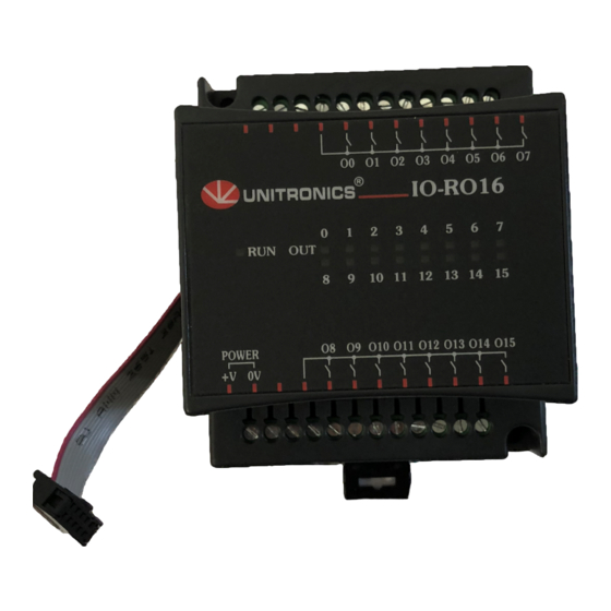
IO-RO16, IO-RO16-L
The IO-RO16 and IO-RO16-L are I/O
expansion modules that can be used in
conjunction with specific Unitronics OPLC
controllers.
The modules are identical except for their
power supply specifications: IO-RO16 runs
at 24 VDC; IO-RO16-L at 12 VDC.
Each module offers 16 relay outputs.
The interface between a module and the
OPLC is provided by an adapter.
These modules may either be snap-
mounted on a DIN rail, or screw-mounted
onto a mounting plate.
Component identification
1
Module-to-module connector
2
Communication status indicator
3
Outputs' power supply
connection points
4
Output connection points: O8-O15
5
Output's status indicators
6
Module-to-module connector port
7
Output connection points: O0-O7
Before using this product, it is the responsibility of the user to read and understand this document and
any accompanying documentation.
All examples and diagrams shown herein are intended to aid understanding, and do not guarantee
operation. Unitronics accepts no responsibility for actual use of this product based on these examples.
Please dispose of this product in accordance with local and national standards and regulations.
Only qualified service personnel should open this device or carry out repairs.
User safety and equipment protection guidelines
This document is intended to aid trained and competent personnel in the installation of this equipment as
defined by the European directives for machinery, low voltage, and EMC. Only a technician or engineer trained
in the local and national electrical standards should perform tasks associated with the device's electrical wiring.
Symbols are used to highlight
information relating to the user's
personal safety and equipment
protection throughout this document.
When these symbols appear, the
associated information must be read
carefully and understood fully.
Failure to comply with appropriate safety guidelines can result in severe personal injury or
property damage. Always exercise proper caution when working with electrical equipment.
Unitronics Industrial Automation
I/O Expansion Modules
1
2
3
Symbol
Meaning
Danger
Warning
Caution
Caution
16 Relay Outputs
Description
The identified danger causes physical
and property damage.
The identified danger can cause
physical and property damage.
Use caution.
7
6
5
4
1
Advertisement
Table of Contents

Related Manuals for Unitronics IO-RO16


Summary of Contents for Unitronics IO-RO16
- Page 1 All examples and diagrams shown herein are intended to aid understanding, and do not guarantee operation. Unitronics accepts no responsibility for actual use of this product based on these examples. Please dispose of this product in accordance with local and national standards and regulations.
-
Page 2: Environmental Considerations
Snap the device onto the DIN rail as shown below; the module will be squarely situated on the DIN rail. 80mm (3.15") Screw-Mounting The figure on the next page is drawn to scale. It may be used as a guide for screw-mounting the module. Mounting screw type: either M3 or NC6-32. Unitronics Industrial Automation... - Page 3 5/03 IO - RO 16, IO -RO 16-L I / O E x p a n s i o n M o d u l e s 80mm (3.15") 5.8mm 68.4mm (0.228") (2.693") (0.16") 4mm (x2) (0.16") Unitronics Industrial Automation...
-
Page 4: Connecting Expansion Modules
To avoid damaging the wire, do not exceed a maximum torque of 0.5 N·m (5 kgf·m). Do not use tin, solder, or any other substance on stripped wire that might cause the wire strand to break. Install at maximum distance from high-voltage cables and power equipment. Unitronics Industrial Automation... - Page 5 DC load, as shown in the left-hand figure below. an RC snubber circuit in parallel with each inductive load, as shown in the right-hand figure below.. (12/24VDC) L1, L2, L3 115/230VAC Unitronics Industrial Automation...
- Page 6 IO -RO 16, IO -RO 16-L 5/03 I / O E x p a n s i o n M o d u l e s IO-RO16, IO-RO16-L Technical Specifications Max. current consumption 60mA maximum from the adapter’s 5VDC 0.18W @ 5VDC...
- Page 7 RO8 is always assigned the number 7. Its I/Os are addressed accordingly. Example Input #5, located on an EX90-DI8-RO8 connected to an M90 OPLC will be addressed as I 149, 149 = 32 + 7 • 16 + 5 Unitronics Industrial Automation...
- Page 8 Unitronics supports a global network of distributors and sales representatives, as well as a U.S. subsidiary. For more information regarding Unitronics products, contact your distributor, Unitronics headquarters via email: export@unitronics.com, or visit the Unitronics website at http://www.unitronics.com/.
Need help?
Do you have a question about the IO-RO16 and is the answer not in the manual?
Questions and answers