Table of Contents
Advertisement
Available languages
Available languages
Quick Links
Advertisement
Chapters
Table of Contents

Related Manuals for BD Sensors AX18-DPT200


Summary of Contents for BD Sensors AX18-DPT200
- Page 1 Betriebsanleitung…..2 User Manual………..21 AX18-DPT200, AX18-DGP200, AX18-DGP100 AX18B-DPT200, AX18B-DGP200 Differenz-Druckmessumformer für die Prozessindustrie Differential Pressure Transmitter for the Process Industry ID: BA_AX18-DPT-DGPx00 Version: 12.2018.0...
-
Page 2: Table Of Contents
DEUTSCH Inhalt 1. Allgemeines ........................3 2. Produktidentifikation......................6 3. Montage ........................... 7 4. HART Kommunikation ....................10 5. Besonderheiten im Ex-Bereich ..................10 6. Elektrische Installation ....................12 7. Erstinbetriebnahme ......................14 8. Bedienung ........................15 9. Wartung ......................... 19 10. -
Page 3: Allgemeines
1. Allgemeines 1.1 Informationen zur Betriebsanleitung Diese Betriebsanleitung gibt wichtige Informationen zum sachgemäßen Umgang mit dem Gerät. Lesen Sie diese Betriebsanleitung deshalb vor Montage und Inbetriebnahme sorg- fältig durch. Halten Sie sich an Sicherheitshinweise und Handlungsanweisungen, die in dieser Be- triebsanleitung aufgeführt sind. - Page 4 1.3 Qualifikation des Personals Montage, Inbetriebnahme, Betrieb, Wartung, Außerbetriebnahme und Entsorgung dürfen nur von fachspezifisch qualifiziertem Personal durchgeführt werden. Arbeiten an elektrischen Teilen dürfen nur von einer ausgebildeten Elektrofachkraft in Übereinstimmung mit den geltenden Vorschriften und Richtlinien ausgeführt werden. 1.4 Haftungsbeschränkung Bei Nichtbeachtung der Anleitungen, technischen Vorschriften, unsachgemäßer und nicht bestimmungsgemäßer Verwendung, Veränderung oder Beschädigung des Gerätes übernimmt der Hersteller keine Haftung.
- Page 5 1.6 Sicherheitstechnische Höchstwerte 1.6.1 Eigensichere Ausführung AX18-D***00 Zulassung: IBExU 14 ATEX 1273 X / IECEx IBE 16.0005X Aluminium Druckgussgehäuse: Gruppe II: II 1/2G Ex ia IIC T4 Ga/Gb / II 2D Ex ia IIIC T 85 °C Db Edelstahlgehäuse: Gruppe I (Bergbau): I M1 Ex ia I Ma Gruppe II: II 1G Ex ia IIC T4 Ga / II 2D Ex ia IIIC T85°C Db...
-
Page 6: Produktidentifikation
2. Produktidentifikation Zur Identifikation des Gerätes dient das Typenschild. Die wichtigsten Daten können diesem entnommen werden. Der Bestellcode dient zur eindeutigen Identifikation Ihres Produktes. Einstell- Seriennummer Bestellcode grenzen Ex-Kennzeichnung und Sicherheitstechnische Ex-Baumusterprüfbescheinigungsnummer Höchstwerte Abb. 1 Typenschild Ex ia Abb. 2 Typenschild Ex d HINWEIS: Das Typenschild darf nicht vom Gerät entfernt werden! -
Page 7: Montage
3. Montage 3.1 Montage- und Sicherheitshinweise Lebensgefahr durch Stromschlag oder Explosion Gerät von Stromversorgung trennen Potenzialausgleich im gesamten Verlauf der Leitung durchführen - innerhalb sowie GEFAHR außerhalb des explosionsgefährdeten Bereichs. Gerät nicht montieren, solange Explosionsgefahr besteht. Verletzungsgefahr durch unter Druck entweichende Medien Montage im drucklosen Zustand WARNUNG... - Page 8 Wenden Sie zum Einbau der Geräte keine Gewalt an, um Schäden am Gerät und der Anlage zu verhindern! Bei der Montage im Freien oder in feuchter Umgebung sind folgende Punkte zu beachten: Bitte beachten Sie, dass bei Ihrer Applikation keine Taupunktunterschreitung auftritt, wodurch sich Kondensat bildet und zur Beschädigung des Druck- messgerätes führen kann.
- Page 9 3.3 Montageschritte für Anschlüsse nach DIN 3852 VERWENDEN SIE KEIN ZUSÄTZLICHES DICHTMATERIAL WIE WERG, HANF ODER TEFLONBAND! Vergewissern Sie sich, dass der O-Ring unbeschadet in der vorgesehenen Nut sitzt. Achten Sie darauf, dass die Dichtfläche des aufzunehmenden Teils eine einwandfreie Oberfläche besitzt. (RZ 3,2) Schrauben Sie das Gerät mit der Hand in das Aufnahmegewinde.
-
Page 10: Hart Kommunikation
4. HART Kommunikation Lebensgefahr durch Explosion Eigensicheren Stromkreis zum Einschleifen eines HART -Kommunikationsinterfaces (HART -Kommunikator bzw. HART -Modem) GEFAHR nur unterbrechen, wenn keine Explosionsgefahr vorliegt. ® Dem analogen Ausgangssignal wird ein zusätzliches Signal gemäß der HART ®... - Page 11 5.3 Schematischer Schaltungsaufbau Der Betrieb eines eigensicheren Gerätes im explosionsgefährdeten Bereich erfordert bei der Auswahl der erforderlichen Zenerbarriere bzw. Speisetrenngeräte besondere Sorgfalt, damit die Geräteeigenschaften in vollem Umfang genutzt werden können. Das nachfolgende Schaubild zeigt eine typische Anordnung aus Netzteil, Zenerbarriere, bzw.
-
Page 12: Elektrische Installation
5.6 Prüfkriterien für die Auswahl der Zenerbarriere nicht unterschreiten, wichtig prüfen, welche Bmin Mindestversorgungsspannung bei voller Aussteuerung des Gerätes zur Verfügung steht. Die volle Aussteuerung, d. h. ein maximales bzw. nominales Ausgangssignal (20 mA), erreicht man durch das Anlegen des maximalen physikalischen Eingangssignals (Druck). In der Regel finden Sie zur Auswahl der Zenerbarriere in den technischen Daten der Barriere eine Antwort. - Page 13 Führen Sie bei Geräten mit Anschlussklemmen den Anschluss so aus, dass die Trennabstände gemäß Norm eingehalten werden und ein Lösen der Verbindungs- leitungen nicht möglich ist. Der Deckel für die Anschlussklemmen und Display kann nur dann geöffnet werden, wenn eine Verschlusssicherung, Madenschraube mit Innensechskant, entfernt wurde.
-
Page 14: Erstinbetriebnahme
Das eigensichere Kabel ist zur eindeutigen Identifikation mit einem hellblauen Schrumpfschlauch (über Kabelisolation) gekennzeichnet. Sollte eine Modifizierung (z. B. Verkürzung) des Kabels unumgänglich sein, wobei die Markierung am Kabelende verloren geht, so ist die Markierung wiederherzustellen (z. B. erneute Kennzeichnung mit einem hellblauen Schrumpfschlauch oder durch ein entsprechendes Markierungsschild). -
Page 15: Bedienung
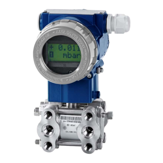
8. Bedienung 8.1 Anzeige- und Bedienmodul Messwert Modus Ausgangs- signal Bargraph Einheit Abb. 5 Drucktaster Abb. 4 Display Dieses Zeichen im Display bedeutet, dass sich das Ausgangssignal linear verhält √ Dieses Zeichen im Display bedeutet, dass sich das Ausgangssignal radizierend verhält Dieses Zeichen zeigt, wenn die Signalgrenzen über- oder unterschritten sind. - Page 16 8.2 Aufbau des Menüsystems 8.3 Menüliste Z-Taste: mit dieser Taste bewegen Sie sich im Menüsystem vorwärts bzw. verändern den Anzeigewert. S-Taste: mit dieser Taste bewegen Sie sich im Menüsystem rückwärts bzw. setzen den Cursor auf eine andere Position. Z+S-Taste: drücken Sie beide Tasten gleichzeitig zur Aktivierung des Menüs, bzw. zur Bestätigung der Menüpunkte und der eingestellten Werte und um den Menüpunkt zu verlassen.
- Page 17 Ist ein Parameter anhand eines Zahlenwertes konfigurierbar, so ist jede Stelle einzeln editierbar. D. h. nach Aktivierung eines solchen Menüpunktes (z. B. DAMPING") durch Betätigung der S-Taste beginnt die erste Ziffer des aktuell eingestellten Wertes zu blinken. Stellen Sie nun mit der Z- Taste die gewünschte Ziffer ein.
- Page 18 OFFSET Verschieben der eingestellten Spanne (nur DPT 200) SHIFT Mit dieser Funktion kann die konfigurierte Spanne entsprechend der Anwendung verschoben werden. Dabei kann dem anliegenden Druck ein bestimmter prozentualer Wert der Spanne zugeordnet werden. Die Größe der eingestellten Spanne wird dabei nicht verändert.
-
Page 19: Wartung
9. Wartung Lebensgefahr durch davonfliegende Teile, austretendes Medium, Stromschlag Demontieren Sie das Gerät immer im druck- GEFAHR und stromlosen Zustand! Verletzungsgefahr durch aggressive Medien oder Schadstoffe - Je nach Messmedium kann von diesem eine Gefahr für den Bediener ausgehen. WARNUNG - Tragen sie geeignete Schutzkleidung, z.B. -
Page 20: Entsorgung
11.2 Rücksendung Verletzungsgefahr durch aggressive Medien oder Schadstoffe - Je nach Messmedium kann von diesem eine Gefahr für den Bediener ausgehen. WARNUNG - Tragen sie geeignete Schutzkleidung, z.B. Handschuhe, Schutzbrille Bei jeder Rücksendung, egal ob zur Nachkalibrierung, Entkalkung, zum Umbau oder zur Reparatur, ist das Gerät sorgfältig zu reinigen und bruchsicher zu verpacken. - Page 21 ENGLISH Content 1. General information ....................... 22 2. Product identification...................... 25 3. Mechanical installation ....................26 4. HART communication ....................29 5. Special considerations in IS-areas ................. 29 6. Electrical installation ...................... 31 7. Commissioning ......................33 8. Operation ........................33 9.
-
Page 22: General Information
1. General information 1.1 Information concerning the user manual This user manual contains important information regarding the proper handling of the device. You must therefore read this user manual carefully before installation and commissioning. Follow the safety and handling instructions that are set out in this user manual. Compliance with the applicable accident prevention regulations and safety regulations as well as with national installation standards and recognised codes of practice must also be ensured. - Page 23 1.3 Qualification of personnel Installation, commissioning, operation, maintenance, decommissioning and disposal may be carried out only by appropriately qualified specialist personnel. Work on electrical components must be performed only by a qualified electrician and in accordance with the applicable regulations and guidelines. 1.4 Limitation of liability Failure to observe the instructions or technical regulations, improper use and use not as intended, and alteration of or damage to the device will result in the forfeiture of warranty...
- Page 24 1.6 Maximum safety limits 1.6.1 Intrinsically safe version AX18-D** *00 Certification: IBExU 14 ATEX 1273 X / IECEx IBE 16.0005X Aluminum die cast housing: Group II: II 1/2G Ex ia IIC T4 Ga/Gb / II 2D Ex ia IIIC T 85 °C Db Stainless steel housing: Group I (mines): I M1 Ex ia I Ma...
-
Page 25: Product Identification
2. Product identification The device can be identified by means of the manufacturing label with order code. The most important data can be gathered therefrom. Serial Order code Setting limits Type number Maximum safety Ex designation and Ex type limits examination certificate number Fig. -
Page 26: Mechanical Installation
3. Mechanical installation 3.1 Installation and safety instructions Danger of death from electric shock or explosion Disconnect the device from the power supply. Install equipotential bonding along the entire length of the line, both inside and outside the DANGER explosion hazard area. Do not install the device while there is a risk of explosion. - Page 27 When installing outdoors or in humid environments, the following points should be noted: - Please note that your application does not show a dew point, which causes condensation and can damage the pressure transmitter. There are specially protected pressure transmitters for these operating conditions. Please contact us in such case.
- Page 28 3.3 Installation steps for NPT connectors Additional seal materials, e.g. PTFE tape, may be used to provide sealing. Screw the device into the mounting thread by hand. Then tighten it with the open-end wrench (for 1/4" NPT: approx. 30 Nm; for 1/2"...
-
Page 29: Hart Communication
4. HART communication Danger of death from explosion The intrinsically safe circuit for connecting a HART communications interface (HART DANGER communicator or HART modem) may be broken only if there is no risk of an explosion. The analogue output signal is overridden by an additional signal according to the HART ®... - Page 30 5.3 Schematic circuit design The operation of an intrinsically safe transmitter in intrinsic safe areas requires special care when selecting the necessary Zener barrier or transmitter repeater devices to allow the utilization of the device’s properties to the full extent. The following diagram shows a typical arrangement of power supply, Zener barrier and transmitter.
-
Page 31: Electrical Installation
5.6 Test criteria for the selection of the Zener barrier In order not to fall below VS min, it is important to verify which minimum supply voltage is available at full level control of the transmitter. The full level control, i.e. a maximum or nominal output signal (20 mA), can be reached by applying the maximum physical input signal (pressure). - Page 32 The cap for the connector terminals and display can only be opened after a security lock – a grub screw with a hexagon socket – has been removed. The screw is located on the right-hand side underneath the cap. After fitting the cap over display and terminals, the security lock must be screwed in again.
-
Page 33: Commissioning
7. Commissioning Before commissioning the device, check that it has been properly installed, and make sure that it does not show any visible defects. The device may by commissioned only by appropriately qualified and trained personnel who have read and understood the user manual. The device may only be operated within its specifications! (Compare the technical data in the data sheet and the EC-type examination certificate with regard to this.) The instantaneously present output signal can be checked without breaking the current... - Page 34 Devices with and without a display are operated in different ways. Devices without a display: These are operated as follows: Press both buttons for about 2 to 5 sec, briefly release them, and then press Z(ero) or S(pan) for a further 5 – 10 sec. Press to perform the desired operation. Z then sets the 4 mA value to the acting pressure;...
- Page 35 8.3 Menu list Z button: Use this button to move forwards through the menu system or to change the displayed value. S button: Use this button to move backwards through the menu system or to set the cursor to a different position. Z+S buttons: Press both buttons simultaneously to activate the menu, to select a menu item, and to confirm the set value and exit the menu item.
- Page 36 Use the Z and S buttons to set the start value for the measuring range, and then confirm the value by pressing the Z and S buttons simultaneously for at least 2 – 5 seconds. The display shows "OK". SET 100% Sets the end value (as a numerical value in physical units) Use the Z and S buttons to set the end value for the measuring range, and then confirm the value by pressing the Z and S buttons simultaneously for at least 2 –...
-
Page 37: Maintenance
As part of this, regular checks must be carried out regarding corrosion, damage to the diaphragm and signal shift. If the diaphragm is calcified, it is recommended to send the device to BD SENSORS for decalcification. Please note the chapter “Service/Repair” below. -
Page 38: Disposal
11.2 Return Danger of injury from aggressive media or pollutants Depending on the measured medium, this may constitute a danger to the operator. WARNING Wear suitable protective clothing e.g. gloves, goggles. Before every return of your device, whether for recalibration, decalcification, modifications or repair, it has to be cleaned carefully and packed shatter-proofed. -
Page 39: Anlagen / Attachment
15. Anlagen / Attachment EG-Konformitätserklärung / EC Declaration of Conformity... - Page 40 Tel.: +42 (0) 572-4110 11 Fax: +49 (0) 9235-9811-11 Fax: +42 (0) 572-4114 97 Russia China BD SENSORS RUS BD SENSORS China Co, Ltd. 39a, Varshavskoe shosse Room B, 2nd Floor, Building 10, RU - Moscow 117105 No. 1188 Lianhang Rd. 201112 Shanghai,...
Need help?
Do you have a question about the AX18-DPT200 and is the answer not in the manual?
Questions and answers