Table of Contents
Advertisement
Quick Links
DE-631
USER MANUAL
DUALi Inc.
Document Version: 1.10
Last Revised Date: 11
ⓒ
Copyright
2010-11 DUALi Inc. All rights reserved. You are strictly prohibited to copy, disclose, distribute, or use
this document in part or as a whole for any purposes other than those for which this document is disclosed. This
document is copyrighted and contains confidential information and other intellectual property rights of DUALi Inc.
Any unauthorized use, copy, disclosure or distribution constitutes infringement of DUALi's intellectual property
rights.
st
Feb 2014
Advertisement
Table of Contents

Related Manuals for Duali DE-631


Summary of Contents for Duali DE-631
- Page 1 ⓒ Copyright 2010-11 DUALi Inc. All rights reserved. You are strictly prohibited to copy, disclose, distribute, or use this document in part or as a whole for any purposes other than those for which this document is disclosed. This document is copyrighted and contains confidential information and other intellectual property rights of DUALi Inc.
- Page 2 DUALi Inc. reserves the right to make changes to its applications or services or to discontinue any application or service at any time without notice. DUALi provides customer assistance in various technical areas, but does not have full access to data concerning the use and applications of customer's products.
- Page 3 DE-631 User Manual Revision History 2011.05.12 First release 2014.02.11 CPU specification change Version : 1.10 DUALi Inc. (http://www.duali.com)
-
Page 4: Table Of Contents
Contents Summary ..........................5 Structure ..........................6 The Structure of equipment ..................6 The block diagram of DE-631 ..................7 Description of main Module ..................8 Description of Surface ......................9 The picture of device surface..................9 Communication Cable(RS-232 and RS-485) ............... 9 Communication Cable(USB).................. -
Page 5: Summary
DE-631 User Manual Summary ITEM Specification Note STM32F103ZET6 (ARM Cortex_M3, 144pin) Program Memory 512KBytes FLASH (default) On chip Up to 8Mbytes external Flash Option (1M,2M,4M,8M) Data Memory 64KBytes SRAM (default) On chip Up to 8Mbytes external PSRAM Option (1M,2M,4M,8M) DISPLAY... -
Page 6: Structure
Structure The Structure of equipment - DE-631 itself contains all circuits include antenna, 4 SAM connectors. - User can order RS-232 version or USB version. (Communication Cable is different) ( R S - 2 3 2 o r R S - 4 8 5 ) -
Page 7: The Block Diagram Of De-631
DE-631 User Manual The block diagram of DE-631 Antenna 4 * status LEDs Power (DC 7.5 ~ 24V) LCD(128*64 graphic) (or DC 5V ) Battery Nor Flash STM32F103 Tamper switch (512Kbytes Flash, RF Control 64Kbytes SRAM, 84bytes Battery backup SRAM... -
Page 8: Description Of Main Module
SAM part: It can control 4 SAMs. And each slot can be operated independently. LED: It has 4 LEDs to display status of communication and card process. LCD : DE-631 has 128*64 graphic LCD Module Battery: It maintains RTC and battery backup SRAM while power is not supplied. -
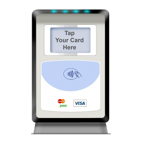
Page 9: Description Of Surface
DE-631 User Manual Description of Surface The picture of device surface Communication Cable(RS-232 and RS-485) (Connector for RS-232 and RS-485 version) Default: RS-232 version Option1: RS-485 version Cable assembly from this connector to POS is optional. Communication Cable(USB) Option2: USB version – Standard A type connector. -
Page 10: Connector Pin Assignment
DE-631 User Manual Connector Pin Assignment RS-232 Connector and Cable RJ-48 Pin No. Description DC POWER(DC9V or 12V) To DC Jack DC POWER(DC 5V) TxD(to Host Rx) RxD(to Host Tx) To DC Jack DC JACK D i a m e t e r = 2 m m D C + ( 9 V o r 1 2 ) D i a m e t e r = 6 . -
Page 11: Usb Connector
DE-631 User Manual - Its default communication method is RS-232. - DC jack’s connection is same with RS-232 version. USB Connector Pin No. Description VCC(DC5V) USB D- USB D+ USB communication method is for firmware development. The current in this USB mode is not enough so the LCD would blink when you access RF card. -
Page 12: Description Of Electricity
DE-631 User Manual Description of Electricity The Description of power Input power1 : 12V Adaptor (higher than 300mA) Input power2 : 5V (USB Bus Powered) The using electric current Normal 12V, 130mA under 12V, 200mA under The Description of USB communication USB V2.0 FULL SPEED (12Mbps) -
Page 13: Description Of Function
DE-631 User Manual Description of Function Protocol Specification Refer to protocol specification for detail function. (Provide on request) Firmware Download Refer download manual. (Provide on request) Property Environment to use Temperature to use : -10 ~ 60 ℃ Humidity to use : 30 ~ 90 % (relative humidity) -
Page 14: Warranty & Service
‣ Warranty and Repair service - DUALi Inc. warrants to the original consumer or other end user that this product, DE-631, is free from defects in materials and workmanship for a period of 1 year from the date of purchase.
Need help?
Do you have a question about the DE-631 and is the answer not in the manual?
Questions and answers