Table of Contents
Advertisement
Quick Links
PROFIBUS Optical Bus Terminal
(OBT)
SIMATIC NET
PG/PC - PROFIBUS
PROFIBUS Optical Bus Terminal
(OBT)
Operating Instructions
04/2016
C79000-G8976-C122-07
___________________
Introduction
___________________
Components of the product
___________________
Functional description
___________________
Network topology
___________________
Commissioning
___________________
Help with problems during
operation
___________________
Technical data
___________________
Approvals and certificates
1
2
3
4
5
6
7
8
Advertisement
Table of Contents

Related Manuals for Siemens SIMATIC NET PG PROFIBUS


Summary of Contents for Siemens SIMATIC NET PG PROFIBUS
- Page 1 ___________________ PROFIBUS Optical Bus Terminal Introduction (OBT) ___________________ Components of the product ___________________ SIMATIC NET Functional description ___________________ Network topology PG/PC - PROFIBUS PROFIBUS Optical Bus Terminal ___________________ (OBT) Commissioning ___________________ Help with problems during operation Operating Instructions ___________________ Technical data ___________________ Approvals and certificates 04/2016...
- Page 2 Note the following: WARNING Siemens products may only be used for the applications described in the catalog and in the relevant technical documentation. If products and components from other manufacturers are used, these must be recommended or approved by Siemens. Proper transport, storage, installation, assembly, commissioning, operation and maintenance are required to ensure that the products operate safely and without any problems.
-
Page 3: Table Of Contents
Table of contents Introduction ............................. 5 Components of the product ........................7 Functional description ..........................9 Interfaces ..........................9 Opto-electrical signal conversion and signal regeneration ............9 Supported FO fiber types ......................10 Displays ..........................10 Operator controls ........................12 Network topology .......................... - Page 4 Table of contents PROFIBUS Optical Bus Terminal (OBT) Operating Instructions, 04/2016, C79000-G8976-C122-07...
-
Page 5: Introduction
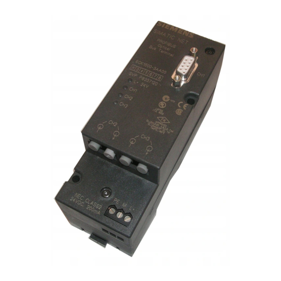
Introduction The PROFIBUS OBT (Optical Bus Terminal) it is a network component used in optical PROFIBUS DP fieldbus networks. It allows the connection of either a single device without an integrated optical interface or an RS-485 segment to the optical PROFIBUS DP. The following figure shows an example of a configuration. - Page 6 Introduction Connections The connection between the individual bus nodes takes the form of an optical bus with two- fiber plastic fiber-optic cables (plastic fiber-optic cables are also known as POF, Polymer Optical Fiber) or PCF fiber-optic cables (PCF = Polymer Cladded Fiber, synonymous with HCS1 fiber-optic cable).
-
Page 7: Components Of The Product
Components of the product Supplied ● 1 x PROFIBUS OBT ● 1 x Operating instructions (Compact) A5E03345735-01 Not supplied ● Plastic fiber-optic cables, sold in meters ● Assembly tool for fiber-optic cable connectors ● Operating Instructions for the PROFIBUS OBT ●... - Page 8 Components of the product PROFIBUS Optical Bus Terminal (OBT) Operating Instructions, 04/2016, C79000-G8976-C122-07...
-
Page 9: Functional Description
Functional description The OBT is a repeater with 3 channels. Interfaces The OBT has the following interfaces for connection of PROFIBUS DP segments: ● Channel 1 (CH1) is an electrical RS-485 interface. It is designed as a 9-pin D-sub female connector. -
Page 10: Supported Fo Fiber Types
Functional description 3.3 Supported FO fiber types Supported FO fiber types The OBT supports the fiber types listed in the following table: Table 3- 1 Achievable FO cable distance between the two devices on optical PROFIBUS DP Fiber type Link length between 2 devices Plastic FO cable 980/1000 μm with 2 fibers 0.1 to 50 meters and max. - Page 11 Functional description 3.4 Displays CH1, CH2 , CH3 (channel 1 to 3, yellow) not lit: Data is not being received lit yellow: Data is being received Image 3-1 LEDs on the front panel PROFIBUS Optical Bus Terminal (OBT) Operating Instructions, 04/2016, C79000-G8976-C122-07...
-
Page 12: Operator Controls
Functional description 3.5 Operator controls Operator controls The OBT itself does not have any controls. The only point to remember is that the PROFIBUS connecting cable connected to channel 1 (does not ship with product) needs to be terminated at both ends. PROFIBUS Optical Bus Terminal (OBT) Operating Instructions, 04/2016, C79000-G8976-C122-07... -
Page 13: Network Topology
Network topology Optical bus Along with other SIMATIC devices such as the IM 153–2 FO or IM 467 FO, OBTs are connected to optical PROFIBUS DP to form an optical bus. PROFIBUS DP bus nodes with an RS-485 interface are connected to channel 1 of the OBT via bus connectors and a PROFIBUS bus cable. -
Page 14: Integration Of Long Fo Cable Runs
Network topology 4.2 Integration of long FO cable runs Integration of long FO cable runs The maximum permitted length of PCF FO cable with the OBT is 300 m. If longer FO links or other FO cable types, for example glass graded index fibers or monomode fibers are necessary, they can be used by combining OBTs with OLMs (Optical Link Module). -
Page 15: Integrating Rs-485 Segments
Network topology 4.3 Integrating RS-485 segments Integrating RS-485 segments The OBT allows the attachment of a PROFIBUS RS-485 segment. Image 4-2 Example of the integration of RS-485 segments PROFIBUS Optical Bus Terminal (OBT) Operating Instructions, 04/2016, C79000-G8976-C122-07... - Page 16 Network topology 4.3 Integrating RS-485 segments PROFIBUS Optical Bus Terminal (OBT) Operating Instructions, 04/2016, C79000-G8976-C122-07...
-
Page 17: Commissioning
Commissioning Note Use the PROFIBUS OBT only as intended in these Operating Instructions. Note Pay particular attention to all warnings and notices relevant to safety. WARNING Operate the PROFIBUS OBT only with safety extra-low voltage complying with IEC 950 / EN 60 950/VDE 0805 of maximum +28.8 V (typically +24 V). - Page 18 Commissioning Note Make sure that the PROFIBUS OBT is adequately grounded by connecting the DIN rail or mounting plate to local ground with low resistance and inductance. When securing the module to a mounting plate, run a cable from the grounding terminal of the OBT to the nearest possible ground, keeping the cable as short as possible.
- Page 19 Commissioning WARNING This equipment is suitable for use in Class I, Division 2, Groups A, B, C, and D or non- hazardous locations only. WARNING This equipment is suitable for use in Class I, Zone 2, Group IIC or non-hazardous locations only.
-
Page 20: Procedure For Commissioning
Commissioning 5.1 Procedure for commissioning Procedure for commissioning Commissioning the PROFIBUS OBT involves the following steps: ● Mounting the PROFIBUS OBT; ● Connecting the power supply; ● Connecting the optical bus cables; ● Connecting the electrical RS-485 bus cable. Installation Mounting the PROFIBUS OBT The PROFIBUS OBTs can be mounted either on a 35 mm DIN rail with a height of 15 mm according to DIN 50 022 - 35 x 15 or directly on a flat surface. - Page 21 Commissioning 5.2 Installation Image 5-1 Mounting a module on a DIN rail Mounting on a mounting plate The PROFIBUS OBTs have two holes. These allow mounting on any flat surface, for example on the mounting plate of a cabinet. Drill two holes in the mounting plate as shown in the drilling template in Figure 5-2. Secure the module with two machine screws (for example M3 x 75 and M3 x 55).
- Page 22 Mounting a module on a mounting plate Instructions for assembling plastic fiber-optic cable (with photos) You will find detailed instructions (with photos) on fitting connectors to plastic fiber-optic cables on the Internet (https://support.industry.siemens.com/cs/de/en/view/35222591) PROFIBUS Optical Bus Terminal (OBT) Operating Instructions, 04/2016, C79000-G8976-C122-07...
- Page 23 Commissioning 5.2 Installation Connecting the operating power supply Image 5-3 Pin assignment of the 3-pin terminal block – grounding terminal ↓ and power supply M, 1. Supply the PROFIBUS OBT only with a stabilized safety extra-low voltage complying with IEC 950 / EN 60 950/VDE 0805 of nominally 24 V (minimum 19.2 V and maximum 28.8 V).
- Page 24 Commissioning 5.2 Installation Connecting the optical bus cables Image 5-4 View of the module from the side with the optical channels CH2 and CH3 A = CH2, optical receiver B = CH2, optical transmitter C = CH3, optical receiver D = CH3, optical transmitter Connect the individual PROFIBUS OBTs using a duplex fiber-optic cable fitted with two pairs of simplex connectors.
- Page 25 Commissioning 5.2 Installation The fiber of the FO cable must be flush with the surface of the connector. Note If the fiber juts out beyond the surface of the connector, the connector must not be inserted in the socket. Otherwise there is a risk of destroying the optical components. Connecting the electrical RS-485 cable Channel CH1 is used to connect a single PROFIBUS DP end device or an RS-485 segment.
- Page 26 Commissioning 5.2 Installation PROFIBUS Optical Bus Terminal (OBT) Operating Instructions, 04/2016, C79000-G8976-C122-07...
-
Page 27: Help With Problems During Operation
Help with problems during operation Help with problems during operation LED display Possible cause of problems L+ 24 V LED not lit Power supply failed • OBT defective • L+ 24 V LED flashes The transmission speed could not be set •... - Page 28 Help with problems during operation 6.1 Help with problems during operation PROFIBUS Optical Bus Terminal (OBT) Operating Instructions, 04/2016, C79000-G8976-C122-07...
-
Page 29: Technical Data
Technical data Table 7- 1 Technical specifications General Operating voltage (safety extra-low voltage, SELV or to NEC 24 V= (19.2 V to 28.8 V) Class 2) Current consumption at 24 V input max. 180 mA Bleed resistance between terminal M and terminal 11 Mohms Transmission speed 12 Mbps, 6 Mbps, 3 Mbps, 1.5 Mbps, 500 Kbps, 187.5 Kbps... - Page 30 Technical data Optical channel Permitted FO cable attenuation (with link power margin) – with plastic fiber 980/1000 13 dB – with PCF fiber 200/230 3 dB Link distance with 3 dB link power margin – with plastic fiber 980/1000 with max. 200 dB/km cable 0.1 m to 50 m attenuation –...
- Page 31 Technical data Climatic environmental conditions Relative humidity < 95% (no condensation) (IEC 60068-2-30) Fast change of temperature during operation 0 °C to +60 °C; exposure time 3 h; temperature change 3 K/min.; 5 cycles (IEC 60068-2-14) Mechanical environmental conditions Oscillation in operation 10 to 58 Hz, 0.075 mm excursion 58 to 150 Hz, 10 m/s2 (1g) acceleration (IEC 60068-2-6)
- Page 32 Technical data PROFIBUS Optical Bus Terminal (OBT) Operating Instructions, 04/2016, C79000-G8976-C122-07...
-
Page 33: Approvals And Certificates
Declaration of conformity The EC Declaration of Conformity is available for the responsible authorities according to the above-mentioned EC directive at the following address: Siemens Aktiengesellschaft Process Industries and Drives Division Process Automation Industrial Communication and Identification PD PA CI R&D... - Page 34 Approvals and certificates 8.1 Notes on the CE mark Installation guidelines The product meets the requirements if you adhere to the installation guidelines included in Optical Bus Terminal PROFIBUS OBT documentation during installation and operation. The accessible radiation power of the transmit LEDs used complies with Class 1 according to 60950-1: 2006 + A11 + A1 + A12 + A2, EN 60825-1: 2014 and EN 60825-2: 2004 + A1: 2007 + A2: 2010 The accessible radiation powers after opening the FO cable deliberately or accidentally...
- Page 35 Approvals and certificates 8.1 Notes on the CE mark IECEx The SIMATIC NET products meet the requirements of explosion protection according to IECEx. IECEx classification: Ex nA IIC T4 Gc DEK 14.0025X The products meet the requirements of the following standards: ●...
- Page 36 Approvals and certificates 8.1 Notes on the CE mark PROFIBUS Optical Bus Terminal (OBT) Operating Instructions, 04/2016, C79000-G8976-C122-07...