Table of Contents
Advertisement
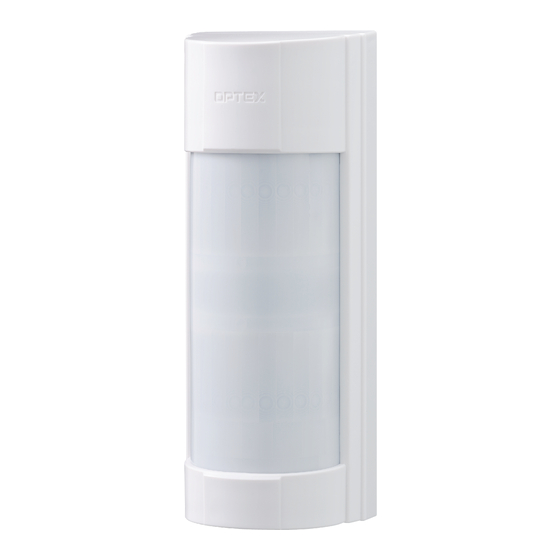
MULTI DIMENSIONAL OUTDOOR DETECTOR
MULTI DIMENSIONAL OUTDOOR DETECTOR
VX Infinity
VX Infinity
WIRED MODEL
VXI-ST
Standard model with 2 PIR
VXI-AM
VXI-ST with anti-masking
VXI-DAM
VXI-AM with micro-wave
TM
The VX Infinity
report losses. The VX Infinity
outdoor environments.
FEATURES
BASIC FEATURES
- 12 m (40 ft.) by 90 degree flexible detection pattern adjustable to 5 ranges
- SMDA Logic for advanced temperature compensation and environmental noise immunity.
- Easy Masking for over spill prevention
- Double Conductive Shielding against bright light disturbance.
- Conduit/TX-Battery Case for both wired and wireless-ready models.
OPTIONAL FEATURES
- Active IR Anti-Masking for detecting covering objects
- Tough Mod Dual Technology based on OPTEX gold-plated microwave module
CONTENTS
1
2
TM
series
TM
series
series provide highly reliable detection functions, reducing false reports or
TM
series deliver stable detection performance even in severe
INSTALLATION INSTRUCTIONS
2
3
3
4
4
5
4
6
4
6-1 SPECIFICATIONS
5
5
7
6
7
7
8
-1-
No. 59-1935-1
8
9
10
12
13
14
14
15
Advertisement
Table of Contents

Related Manuals for Optex VX Infinity Series


Summary of Contents for Optex VX Infinity Series
-
Page 1: Table Of Contents
- Double Conductive Shielding against bright light disturbance. - Conduit/TX-Battery Case for both wired and wireless-ready models. OPTIONAL FEATURES - Active IR Anti-Masking for detecting covering objects - Tough Mod Dual Technology based on OPTEX gold-plated microwave module CONTENTS INTRODUCTION 2-9 AREA MASKING... -
Page 2: Introduction
INTRODUCTION 1-1 BEFORE INSTALLATION Failure to follow the instructions provided with this indication and improper handling may cause Warning death or serious injury. Failure to follow the instructions provided with this indication and improper handling may cause Caution injury and/or property damage. The check mark indicates recommendation. -
Page 3: Parts Identification
VXI-ST -Precautions for installing two or more sensors VXI-AM VXI-DAM Do not install two or more VXI-DAMs in side by side or face to face. Doing so may cause malfunction. VXI-DAM may be installed in back to back. If mounting on the same wall, make sure that each unit is at least 1.0 m (3.28 ft) apart from the other. -
Page 4: Detection Area
1-3 DETECTION AREA SIDE VIEW Length limiting position 1 (Default) Note>> The maximum detection length may vary as shown below due to environment conditions. Length limiting position 2 TOP VIEW Area diagram of horizontal position D Length limiting position 3 A B C E F G Length limiting position 4... -
Page 5: Mounting
2-3 MOUNTING Mount the mounting plate. Wall mount Pole mount Wiring hole Metal band * Use a metal band with 25 mm or less in width. Electric gang box mount Conduit installation An electric gang box can be connected. Open the knockout located at Connect the pipe and back the bottom of the back box. -
Page 6: Mounting With Back Box
2-5 MOUNTING WITH BACK BOX When a certain distance from the mounting surface is required for purposes such as avoiding an unwanted object, use the back box to install the unit. Open a wiring knockout on the back box and pass the wire from the mounting plate. Wiring sponge Open a wiring knockout inside the back box. -
Page 7: Wiring
2-6 WIRING Wiring terminal is located on the upper part of the main box. <VXI-ST> <VXI-AM> <VXI-DAM> Terminals -Power cable length The power cable should be limited to the following length. VXI-ST VXI-AM VXI-DAM Current draw 20 mA Current draw 24 mA Current draw 35 mA WIRE GAUGE 12 V... -
Page 8: Area Angle Adjustment
2-8 AREA ANGLE ADJUSTMENT Horizontal position D Horizontal position B (Default) (F: symmetrical position) A B C A B C E F G E F G A B C E F G Horizontal position C Horizontal position A (E: symmetrical (G: symmetrical position) position) -
Page 9: Detection Length Adjustment
2-10 DETECTION LENGTH ADJUSTMENT Adjust the PIR detection length by sliding the lower PIR to the desired position. IMPORTANT BOTH DETECTION AREAS MUST BE BLOCKED FOR DETECTION Both upper and lower detection area are blocked Detection! Only upper detection area is blocked Adjust the MW detection length by rotating the MW sensitivity adjustment according to the PIR area. -
Page 10: Switch Setting
SWITCH SETTING VXI features can be set on/off by DIP switch settings. DIP switch PIR sensitivity selector 1 LED 2 ALARM OUTPUT 3 AUX INPUT 4 ANTI-MASKING 5 MICROWAVE IMMUNITY MW sensitivity adjustment VXI-ST -LED VXI-AM DIP switch 1 VXI-DAM POSITION FUNCTION LED ON... - Page 11 VXI-ST -AUX INPUT VXI-AM DIP switch 3 VXI-DAM By connecting a secondary unit (another warning sensor), you can extend the detection area and correct false alarms. The secondary unit must have a voltage free N.C. output such as another PIR detector or AIR detector. <Infrared (AIR) sensors, thermal line (PIR) sensors, magnet switches, etc.>...
-
Page 12: Walk Test
VXI-ST -MICROWAVE IMMUNITY VXI-AM DIP switch 5 VXI-DAM POSITION FUNCTION MICROWAVE IMMUNITY logic is activated. Use this under IMMUNITY harsh environment (e.g. vegetation sway). MICROWAVE IMMUNITY logic is not activated. (Factory default) STD ⇔ IMMUNITY VXI-ST -PIR SENSITIVITY VXI-AM PIR SENSITIVITY SELECTOR VXI-DAM HIGH POSITION... -
Page 13: Led Indication
LED INDICATION Blink Light YELLOW (VXI-DAM only) <VXI-ST> <VXI-AM> Detector condition LED indicator Warm-up Note>> Blinks for approx. 60 seconds. The LED blinks even if the DIP switch 1 (LED) is set to “OFF”. Alarm Lights for 2 seconds. Masking detection (VXI-AM only) Blinks 3 times and then repeats. -
Page 14: Specifications
SPECIFICATIONS 6-1 SPECIFICATIONS Model VXI-ST VXI-AM VXI-DAM Detection method Passive infrared Passive infrared & Microwave PIR Coverage 12.0 m (40 ft) 90° wide / 16 zones PIR distance limit 12 – 2.5 m (5 levels) Detectable speed 0.3 – 1.5 m/s (0.98 – 4.92 ft/s) Sensitivity 2.0°C (3.6°F) at 0.6 m/s Power input... -
Page 15: Setting Of Special Detection Area
SETTING OF SPECIAL DETECTION AREA Using masking seals 2 to 6, you can set a special detection area for the horizontal position A or G. Set to the desired area setting direction When setting other than masking Select a masking seal from 2 to 6 (horizontal position A or G). - Page 16 The following statement will be provided with the equipment as required by Article 6.3 of the R&TTE Directive, 1999/5/EC. COMPLIANCE The Optex VXI series are in conformity with all essential requirements of the R&TTE Directive (1999/5/EC). • VXI series complies with following Directives / Standards.
Need help?
Do you have a question about the VX Infinity Series and is the answer not in the manual?
Questions and answers