Advertisement
Table of Contents
- 1 Table of Contents
- 2 Getting to Know Your
- 3 Powersafe Switch Box
- 4 Parts Description
- 5 Spares Codes
- 6 Technical Specification
- 7 Installation
- 8 Mounting the Switch Box
- 9 Electrical Installation
- 10 Maintenance
- 11 Replacing a Fuse
- 12 Faults Problems Procedure
- 13 Consumer Advice Contact Details
- 14 Returning a Faulty Switch Box
- Download this manual
garden power switch
box 2/3/4/5 way
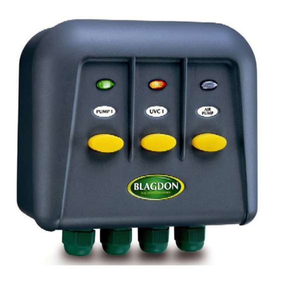
Congratulations on buying a Blagdon Powersafe Switch box.
The Powersafe range of switch boxes has been specifically designed to
protect your equipment from failure. Each individual double pole switch
gives total electrical isolation when switched off. Each switch features
the unique at-a-glance power status indication system, which enables
quick identification of power on, power on standby and power failure
due to a blown fuse. Each switch has an individual fuse to provide
overload protection ensuring that even if one or more items of
equipment fail, the other essential equipment is still able to function.
Please attach proof of purchase to this manual and file in a safe place.
Powersafe Switch box ........................................ 2
Wiring
diagram........................... inside front cover
......................... inside front cover
.......................................................... 2
.......................................... 2
Installation ......................................................... 3 - 7
........................................ 4 - 7
IMPORTANT
CONTENTS
..................................... 4
Maintenance .......................................................... 7
..................................................... 7
Maintenance
........................................................... 7
Faults problems procedure ................................. 8
....................... 8
............................. 8
1
Advertisement
Table of Contents

Summary of Contents for Blagdon Powersafe Series
-
Page 1: Table Of Contents
2/3/4/5 way Congratulations on buying a Blagdon Powersafe Switch box. The Powersafe range of switch boxes has been specifically designed to protect your equipment from failure. Each individual double pole switch gives total electrical isolation when switched off. Each switch features... -
Page 2: Getting To Know Your
GETTING TO KNOW YOUR GARDEN POWER SWITCH BOX Part Description Spare Code Part Description Spare Code Cover locating screws 5 AMP fuse 1040433 (set of four) 1040372 1.5 AMP fuse 1040440 Fixing bracket 1040389 Cable clamp and screws 1040457 Fixing bracket screws Central PCB locating screw 1040464 and plugs set 1040396... -
Page 3: Installation
INSTALLATION UVC FILTER 5 WAY GARDEN SWITCH BOX LIGHTING HOSE ELECTRONIC BLANKET WEED CONTROLLER INPOOL POND PUMP FOR WATERFALLS, LIGHTING FILTERS AND FOUNTAINS AIR PUMP RCD SOCKET OR PLUG (HOUSE, SHED or GARAGE) Example shown is 5 way Garden Power Switch box IMPORTANT: This outlet box is intended to be used with either a weatherproof cable connector or permanently connected to the fixed wiring of the mains system other than by means of a plug and socket. -
Page 4: Mounting The Switch Box
INSTALLATION IMPORTANT: Please note all electrical work on garden lighting and power installations must comply with part P of the building regulations. Failure to comply is a criminal offence. If the installation of this product is not carried out by a competent electrician who is registered under the Part P self-certification scheme then you must notify the local building control department before work begins. - Page 5 INSTALLATION Circuit Board Removal Remove the circuit board by unscrewing the locating screw and wire each appliance before replacing and locating into the box. Prepare the cable (see cable preparation diagram - inside front cover). A maximum external cable diameter of 9mm is permitted. IMPORTANT: Please note that the mains input must be connected to the green power input cable block only.
- Page 6 INSTALLATION Remove the rubber seal from the cable gland and thread it over the cable of the appliance to be fitted. At this stage leave the gland cover and rubber seal loose on the cable. Remove the central circuit board locating screw that locates the circuit board and store in a safe place.
-
Page 7: Maintenance
INSTALLATION Switch Box Mounting See power status indicator lights diagram page 2 for status of the Switch box fuses. If one of the fuses fails the power indicator will not light on the switch that has failed. Please note that if the power supply to the switch box has been switched off or interrupted due to the RCD circuit breaker or fuse from the mains supply isolating the box none of the indicator lights will illuminate. -
Page 8: Faults Problems Procedure
IMPORTANT FAULTS - PROBLEMS PROCEDURE Before returning your Blagdon pump to your dealer or contacting our Consumer Advice Department, please carry out the following steps. These will solve most problems quickly and easily: Ensure electrical procedure has been followed fully. Check fuses and any cable connectors or switch boxes.

Need help?
Do you have a question about the Powersafe Series and is the answer not in the manual?
Questions and answers