
Subscribe to Our Youtube Channel
Related Manuals for ANDERSON-NEGELE ILM-4


Summary of Contents for ANDERSON-NEGELE ILM-4
- Page 1 SENSORS FOR FOOD AND LIFESCIENCE. Operating Manual Inductive Conductivity Meter ILM-4 / ILM-4R 30012 / 3.4 / 2019-12-16 / AR / EU ILM-4 / ILM-4R...
-
Page 2: Table Of Contents
Electrical Connection Analog Signal Modules ........21 Electrical Connection Digital Signal Modules ........24 ILM-4 IO-Link Device Identity ..............26 ILM-4 IO-Link User Interface ..............27 ILM-4 IO-Link Process Data Description ..........28 Repair and maintenance ................ 31 Technical data ..................31... -
Page 3: Application / Intended Use
Operating Manual ILM-4 Application / Intended use • Inductive measurement of specific conductivity and concentration of fluid media in the range of 0…1000 mS / cm • For use in hygienic applications of the food, beverage, and pharmaceutical industries •... -
Page 4: Special Features / Advantages
Operating Manual ILM-4 Special features / advantages • The sensor structure is based on a modular device platform which can be tailored to re- quirements and is easy to exchange if faulty • Wear-free, inductive measurement procedure • In contrast to conductive measurement procedures, there are no problems due to elec- trode deterioration or polarization. -
Page 5: Requirements For Hygienic Installation
Requirements for hygienic installation Conditions for hygienic installation according 3A and EHEDG • The ILM-4 / ILM-4R is designed for CIP/SIP cleaning. The sensor can withstand a maximum of 150 °C / 60 min. • The mounting position must guarantee self-draining properties. - Page 6 The device should be aligned so that the "FLOW" label on the bottom of the de- vice in the direction of flow. The ILM-4 inductive conductivity meter is set to operate without requiring special adapta- tions. In isolated instances, some parameters may need to be adjusted. The parameterization may be changed using the PC-based MPI-200 programming adapter or the User Interface di- rectly on the sensor.
- Page 7 User Interface with Display The ILM-4 inductive conductivity meter features a modular design with a “tree structure”, which can be tailored to meet requirements and can be easily exchanged in the event of a fault.
- Page 8 Operating Manual ILM-4 The table below shows possible sensor settings and corresponding ID number. Parameter ID Number Adjustable settings Sensor Sensor Settings Temperature Compensation Unit 013021 %/K, %/°F Conductivity 1 Temperature Compensation 1 013031 0…100 %/K Damping Conductivity 1 013041 inactive, 2.5 s, 5 s, 10 s, 20 s...
- Page 9 Operating Manual ILM-4 The table below shows possible display settings and corresponding ID number. Parameter ID Number Adjustable settings Display Settings Display Language 451010 English, German LED 1 (left) Signal Selection 330034 Conductivity 1, Concentration, Conductivity 2, Temperature Warning-Signal: No Media...
-
Page 10: Settings Using The Mpi-200 Programming Adapter
Operating Manual ILM-4 Settings using the MPI-200 programming adapter The MPI-200 programming adapter is connected to the ILM-4 conductivity meter via the external MPI-200-F adapter. It must be ensured that the ILM-4 conductivity meter is permanently connected to the supply voltage while the parameters are being set. - Page 11 Operating Manual ILM-4 To set or change parameters directly in the sensor (see section 6.2 "Settings using the Simple User Interface"), you need the ID codes contained in the table below. This table only lists the most im- portant ID codes.
-
Page 12: Settings Using The User Interface
Operating Manual ILM-4 Settings using the User Interface The software structure of the User Interface is like the structure of the PC version. The system is operated using two control buttons to the left and right or below the display. - Page 13 Operating Manual ILM-4 Menu Structure Menu Menu Menu Menu Menu QuickSetup QuickSetup QuickSetup QuickSetup QuickSetup Setup Setup Setup Setup Setup ID Search ID Search ID Search ID Search ID Search Calibr. Calibr. Calibr. Calibr. Calibr. R l. R l. R l.
-
Page 14: Screen Display
Operating Manual ILM-4 6.4.1 Screen display After the sensor parameters have been adapted/changed, or after the sensor is switched on and no change is made, the sensor shows the current measurement value. By pressing the right button, different measurement values will be shown. After pressing the left button long, the default meas- urement will be displayed. -
Page 15: Settings Of Sensor
Operating Manual ILM-4 Settings of Sensor 7.1.1 Default Settings for LED During normal operation, both LEDs are switched off. The LEDs will indicate different status of the sensor LED 1 (left side) LED 2 (right side) Indication of Warning Indication of Error... -
Page 16: Examples Of Sensor Settings
Operating Manual ILM-4 7.2 Examples of sensor settings Several examples of settings that can be created on the Simple User Interface or on the user inter- face of the PC follow (setting of a customized conductivity 1, the associated temperature coeffi- cient and the concentration curve). -
Page 17: Example For Setting Conductivity 1 Using The Display
Operating Manual ILM-4 7.2.2 Example for setting conductivity 1 using the display Menu Quick Setup Conducty 1 R l. 0 mS/cm Save Data? QuickSetup TempComp C ID: 013091 Setup TempComp 2 Range Cd 1 No / Yes ID Search Range Cd 1 0200.0... -
Page 18: Installation Of The „Large User Interface" (Lui)
Operating Manual ILM-4 Installation of the „Large User Interface“ (LUI) Remove the complete signal module in case a small display (SUI) is mounted (cont. 4) Remove the small display unit from the signal module Install the signal module in the sensor head... -
Page 19: Retrofitting The Display If A Small Display (Sui) Was Already Installed
Operating Manual ILM-4 8.2 Retrofitting the display if a small display (SUI) was already installed First the puck with the mounted display needs to be removed using the puck puller tool (Fig. 4). To do so, detach the wires from the cable terminal. Then insert the five arms of the puck puller in the plastic tabs of the puck (Fig. -
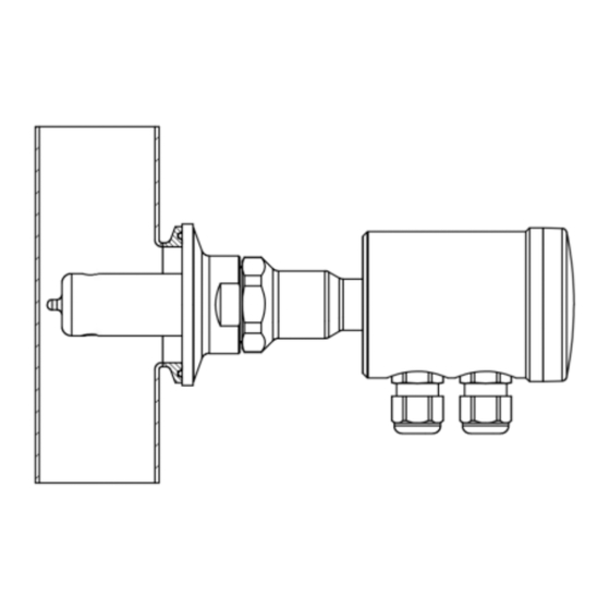
Page 20: Dimensions
Operating Manual ILM-4 Dimensions For all process connections, the conductivity sensor can be ordered with a submersion length of L20 (20 mm) or L50 (50 mm). -
Page 21: Electrical Connection Analog Signal Modules
Operating Manual ILM-4 10 Electrical Connection Analog Signal Modules 10.1 Terminal Block of A5x/A6x Series Power Supply + Power Supply + Power Supply - Power Supply - Not assigned Digital Input X3 Not assigned Digital Input X3 Analog Output X45 +... - Page 22 Operating Manual ILM-4 10.3 M12 Connector Cables Color Anderson Color M12 Connector Standard Color Brown Black White Green Blue Black Not assigned White Grey 10.4 M12 connectors for A6x/A5x series Electrical Connection „N“ M12 Connector Signal Module Connector Analog Output X45 +...
- Page 23 Operating Manual ILM-4 10.5 M12 Connectors for A4x series Electrical Connection „M“ M12 Connector Signal Module Connector Power Supply + Analog Output X45 + Analog Output X45 - Power Supply - Electrical Connection „L“ M12 Connector Signal Module Connector Power Supply +...
-
Page 24: Electrical Connection Digital Signal Modules
Operating Manual ILM-4 Electrical Connection Digital Signal Modules 11.1 Terminal Block of I5x/I6x Series Power Supply + Power Supply + Power Supply - Power Supply - IO-Link / IO-Link / IO-Link IO-Link Digital Input X3 Digital Input X3 Analog Output X45 +... - Page 25 Operating Manual ILM-4 11.3 M12 connector cables color Anderson Color M12 Connector Standard Color Brown Black White Green Blue Black Not assigned White Grey 11.4 M12 connectors for I6x/I5x series Electrical Connection „R“ M12 Connector Signal Module Connector Analog Output X45 +...
-
Page 26: Ilm-4 Io-Link Device Identity
Operating Manual ILM-4 ILM-4 IO-Link Device Identity... -
Page 27: Ilm-4 Io-Link User Interface
Operating Manual ILM-4 ILM-4 IO-Link User Interface... -
Page 28: Ilm-4 Io-Link Process Data Description
Operating Manual ILM-4 ILM-4 IO-Link Process Data Description Name Description Data Value Gra- Off- Unit type length offset range dient Conductivity 1 Measurement Value Float 32 0-1000 of Conductive 1 Temperature Temperature Float 32 0-150 °C °C/°F Measurement Value Concentration... - Page 29 Operating Manual ILM-4 IO-Link Eventlist Measurement Events Event Event Event Name (EN) Event Name (DE) Code Type 36285 Warning Outside specification: Conduc- Außerhalb der Spezifikation: Leit- tivity 1. Currently the sensor is fähigkeit 1. Derzeit ist der Sensor not able to perform a reliable nicht in der Lage, eine zuverläs-...
- Page 30 Operating Manual ILM-4 36300 Warning Underrange: Concentration Untersteuerungsgrenze: Konzentration 36301 Warning Overrange: Concentration Übersteuerungsgrenze: Konzentration 36302 Error Underflow: Concentration Unterlauf: Konzentration 36303 Error Overflow: Concentration Überlauf: Konzentration 36304 Warning No Media: Concentration. Cur- Kein Medium: Konzentration. Der rently the sensor cannot detect...
-
Page 31: Repair And Maintenance
Operating Manual ILM-4 Repair and maintenance The conductivity sensor described here is maintenance-free. However, if it should become nec- essary to calibrate the sensor, the offset (zero point) and the span of the sensor can be set with MPI-Tool (Calibration mode) or using IO-Link. - Page 32 Operating Manual ILM-4 Resolution/ < 1 mS / cm 0,001 mS / cm measurement range < 10 mS/cm 0,01 mS / cm < 100 mS / cm 0,1 mS / cm < 1000 mS / cm 1 mS / cm...
Need help?
Do you have a question about the ILM-4 and is the answer not in the manual?
Questions and answers