Table of Contents
Advertisement
Advertisement
Table of Contents

Summary of Contents for Simrad S5100
- Page 1 S5100 Sonar module Installation manual ENGLISH simrad-yachting.com...
- Page 3 About this manual Intended audience This manual is a reference guide for installing the S5100. The manual is written for marine electronics technicians, and assumes some prior knowledge and skills relevant to the type of work to be carried out.
- Page 4 Trademarks ® Navico is a registered trademark of Navico. ® Simrad is used by license from Kongsberg. ® ® NMEA and NMEA 2000 are registered trademarks of the National Marine Electronics Association. Preface | S5100 Installation Manual...
-
Page 5: Table Of Contents
Connectors and LED location Installation Mounting location Transducer installation Wiring Guidelines Grounding the unit Power connection Connecting the S5100 to MFD systems Transducer connection 14 Troubleshooting LED indicators 15 Maintenance Preventive maintenance Checking the connectors Software update 16 Spare parts and accessories... -
Page 6: Introduction
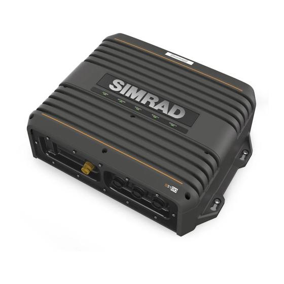
Introduction Overview The S5100 is a networked triple CHIRP module including 3 independent sonar channels. This allows for simultaneous use of High, Medium and Low CHIRP, and for dual independent ranges on a single screen. In addition, each frequency range can be viewed on connected MFDs in the network. -
Page 7: Connectors And Led Location
Connectors and LED location Power connector Grounding screw LED status indicators Ethernet connector Sonar channel 1 Sonar channel 2 Sonar channel 3 Introduction | S5100 Installation Manual... -
Page 8: Installation
Exposing the unit to conditions that exceeds the specifications could invalidate your warranty. – refer to on page 17. "Technical specifications" Transducer installation For transducer installation information, refer to separate installation instructions included with the transducer. Installation | S5100 Installation Manual... -
Page 9: Wiring
(+) DC with the supplied fuse or a circuit breaker (closest available to fuse rating). Grounding the unit For additional safety, install grounding cable in ground screw hole as indicated on the illustration. Recommended 16 awg wire. Wiring | S5100 Installation Manual... -
Page 10: Power Connection
(n/c) 12 - 24 V DC Some MFD systems can be configured for power control. When the S5100 is used in such systems it is recommended to connect the unit to the power control bus and set the MFD to power control master. -
Page 11: Connecting The S5100 To Mfd Systems
S5100 connects to a single MFD (A), and how MFDs with two Ethernet connectors can daisy chain (B) to share sonar data • how sonar data from the S5100 can be shared by connecting the MFDs via a network expansion port (C) Wiring... -
Page 12: Transducer Connection
Transducers with 7 pin connector Transducers with a blue 7 pin connector must be connected to S5100 by using the 7-9 adapter cable. 3 of these adapter cables are included in the box. The adapter cable connects to any of the sonar channels. - Page 13 (A) to the Channel-1 or Channel-2 plug • connect the low frequency element connector (B) to the plug to the immediate right of the plug used for the high frequency connector. Wiring | S5100 Installation Manual...
-
Page 14: Troubleshooting
Troubleshooting LED indicators 5 LEDs on the unit's cover indicate status for the S5100, for the network and for connected transducers. POWER NETWORK CHANNEL-1 CHANNEL-2 CHANNEL-3 Power LED • - No power connection • Check power and power cable •... -
Page 15: Maintenance
Software update You can update the software for the S5100 from a display unit connected to the network. Software version can be viewed on the Echosounder page when the S5100 is selected as the sonar source. -
Page 16: Spare Parts And Accessories
Spare parts and accessories The most up-to-date list of spare parts and accessories is available at the product site on www.simrad-yachting.com. S5100 Spare parts and accessories Item Part number Power cable, length 1.8 m (6 ft) 000-00128-001 Ethernet cable yellow 5 Pin, 2 m (6.5 ft) 000-0127-51 Ethernet cable yellow 5 Pin, 4.5 m (15 ft) -
Page 17: Technical Specifications
Technical specifications Ú Note: The most up-to-date specifications list is available at: www.simrad-yachting.com S5100 Approvals Compliance EMC directive 2014/30/EU Standard IEC 60945 Connectivity Transducer 3 x 9-pin sonar connectors Ethernet 1 x 100 Mbps Power 1 x 4-pins power connector... -
Page 18: Dimensional Drawings
Dimensional drawings S5100 68 mm 250 mm (9.842”) 60 mm (2.673”) (2.344”) 100 mm (3.94”) 109 mm (4.277”) 320 mm 340 mm (12.597”) (13.385”) Dimensional drawings | S5100 Installation Manual...
Need help?
Do you have a question about the S5100 and is the answer not in the manual?
Questions and answers