GE MAC 5000 Service Manual
Resting ecg analysis system
Hide thumbs
Also See for MAC 5000:
- Operator's manual (229 pages) ,
- Field service manual (160 pages) ,
- Operator's manual (258 pages)
Table of Contents
Advertisement
Quick Links
Download this manual
See also:
Operator's Manual
Advertisement
Table of Contents

Related Manuals for GE MAC 5000


Summary of Contents for GE MAC 5000
- Page 1 GE Healthcare MAC ™ 5000 Resting ECG Analysis System Product Code SBZ Service Manual 2024917-010 Revision B...
- Page 2 NOTE: The information in this manual only applies to MAC 5000 with product code SBZ. It does not apply to earlier software versions. Due to continuing product innovation, specifications in this manual are subject to change without notice. MUSE, CASE, MAC, MARS, and 12SL are trademarks owned by GE Medical Systems Information Technologies, a General Electric Company going to market as GE Healthcare.
-
Page 3: Table Of Contents
+18V ............2-10 Revision B MAC 5000 resting ECG analysis system 2024917-010... - Page 4 +1.8V ............2-10 +12V .
- Page 5 Type-S Trolley Assembly ......... . . 3-14 MAC 5000 ST Requirements and Configuration ......3-15 Compatible Blood Pressure Units .
- Page 6 Reassembly ..........4-13 Main CPU Board .
- Page 7 Print Charge/Discharge Test Results ......5-14 Communication Tests ..........5-14 COM Port Loopback Test .
- Page 8 EXT. VID. Pins (J7) ..........5-26 CPU PCB Input/Output Signals .
-
Page 9: Introduction
Introduction Revision B MAC™ 5000 resting ECG analysis system 2024917-010... - Page 10 For your notes MAC™ 5000 resting ECG analysis system Revision B 2024917-010...
-
Page 11: Manual Information
Introduction: Manual Information Manual Information Revision History Each page of the document has the document part number and revision letter at the bottom of the page. The revision letter identifies the document’s update level. The revision history of this document is summarized in the table below. -
Page 12: Warnings, Cautions, And Notes
Introduction: Warnings, Cautions, and Notes Warnings, Cautions, and Notes The terms danger, warning, and caution are used throughout this manual to point out hazards and to designate a degree or level or seriousness. Familiarize yourself with their definitions and significance. Hazard is defined as a source of potential injury to a person. -
Page 13: Safety Messages
U.S. Federal law restricts this device to the sale by or on the order of a physician. Responsibility of the Manufacturer GE Medical Systems Information Technologies is responsible for the effects of safety, reliability, and performance only if: Assembly operations, extensions, readjustments, modifications, or repairs are carried out by persons authorized by us. -
Page 14: General
To ensure patient safety, use only parts and accessories manufactured or recommended by GE Medical Systems Information Technologies. Contact GE Medical Systems Information Technologies for information before connecting any devices to this equipment that are not recommended in this manual. -
Page 15: Equipment Symbols
Introduction: Equipment Symbols Equipment Symbols The following symbols appear on the equipment. Type B equipment. Type BF equipment, external defibrillator protected. Alternating current. When illuminated, the green LED next to this symbol indicates AC power is connected. Equipotential. Charge the battery. The flashing amber LED next to this symbol indicates you must connect the system to AC power to re-charge the battery. - Page 16 Introduction: Equipment Symbols In Europe, this symbol means dangerous or high voltage. In the United States, this symbol represents the caution notice below: CAUTION To reduce the risk of electric shock, do NOT remove cover (or back). Refer servicing to qualified personnel. This symbol indicates that the waste of electrical and electronic equipment must not be disposed as unsorted municipal waste and must be collected separately.
-
Page 17: Service Information
Refer equipment servicing to GE Medical Systems Information Technologies authorized service personnel only. Any unauthorized attempt to repair equipment under warranty voids that warranty. It is the user’s responsibility to report the need for service to GE or to one of their authorized agents. Equipment Identification The Serial Number tag is located inside the device where shown below. -
Page 18: Format A
Manufacturing number (of total units manufactured) number product code Two-character product descriptor. SBZ = MAC 5000 resting ECG analysis system with -006 CPU board. NOTE: Earlier versions used MP, MH, and WT. See the serial tag on your device for the product code. -
Page 19: Format B
(and so on) Fiscal Week Manufactured Production Sequence Number Manufacturing Site Miscellaneous Characteristic 1. This manual applies to MAC 5000 with Product Code SBZ and MP, WT, and AAY (with -006 board upgrade) Format C Table 4. Equipment Identification – Format C... - Page 20 Introduction: Service Information For your notes 1-12 MAC™ 5000 resting ECG analysis system Revision B 2024917-010...
-
Page 21: Equipment Overview
Equipment Overview Revision B MAC™ 5000 resting ECG analysis system 2024917-010... - Page 22 For your notes MAC™ 5000 resting ECG analysis system Revision B 2024917-010...
-
Page 23: General Description
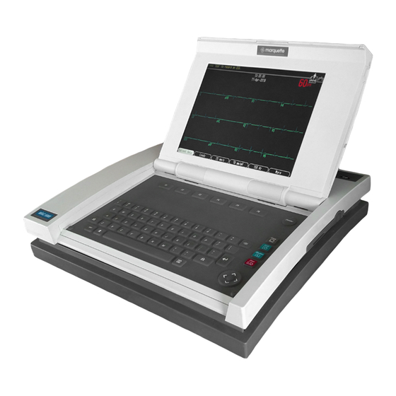
Equipment Overview: General Description General Description The MAC 5000 resting ECG analysis system is a 15 lead, 12 channel system with a 10.4 inch (264 mm) diagonal display, active patient cable, battery operation, and late potential electrocardiography. There are also options for communication capabilities. -
Page 24: Connector Identification
(Ultrasound, stress echo, ergometer, analog treadmill, blood pressure units) EXT.VID. Connect an external video display. Point at a MAC 5000 or MUSE system’s IR transceiver to transmit or receive ECG data. card slot Insert the SD (Secure Digital) card into this slot to update software. -
Page 25: Detailed Description
Equipment Overview: Detailed Description Detailed Description Block Diagram Revision B MAC™ 5000 resting ECG analysis system 2024917-010... -
Page 26: Theory Of Operation
Theory of Operation Overview / Block Diagram The MAC 5000 CPU board contains all of the circuitry for the MAC 5000 electrocardiograph except for the line power supply, acquisition module, keyboard and display. Although MAC 5000 runs software derived from... - Page 27 Equipment Overview: Theory of Operation Atmel AT91RM9200 CPU Containing: ™ ™ Incorporates the ARM920T ARM® Thumb Processor 200 MIPS at 180 MHz, Memory Management Unit 16-KByte Data Cache, 16-KByte Instruction Cache, Write Buffer In-circuit Emulator including Debug Communication Channel Mid-level Implementation Embedded Trace Macrocell (256-ball BGA Package Only) Low Power: 30.4 mA on VDDCORE, 3.1 mA in Standby Mode Additional Embedded Memories...
- Page 28 Equipment Overview: Theory of Operation Four Universal Synchronous/Asynchronous Receiver/ Transmitters (USART) Support for ISO7816 T0/T1 Smart Card Hardware and Software Handshaking RS485 Support, IrDA Up To 115 Kbps Full Modem Control Lines on USART1 Master/Slave Serial Peripheral Interface (SPI) 8- to 16-bit Programmable Data Length, 4 External Peripheral Chip Selects Two 3-channel, 16-bit Timer/Counters (TC) Three External Clock Inputs, Two Multi-purpose I/O Pins per...
-
Page 29: Power Supplies
+5V-M The MAC 5000 is not fully in the 3V age. The Super I/O, floppy diskette drive and thermal printhead all require 5V power. The MAX782 provides this rail via another PWM synchronous switching regulator. Moe controls +5V-M in tandem with +3V-M. -
Page 30: Ref2V5
Equipment Overview: Theory of Operation +18V The Main Regulator’s 5V switching output also supports generation of a non-regulated 18V rail, which is used to provide power for the acquisition module. By providing the acquisition module with 11.5V linearly regulated power from the +18V rail of the main regulator rather than the main 12V regulator (U15), acquisition is not affected by excessive current draw from the printer motor or external loads on the COM ports (esp. -
Page 31: Vana+, Vana
Equipment Overview: Theory of Operation VAna+, VAna- The analog output circuitry is powered by a low current switched 12V rail, provided by the Main Regulator. VAna+ provides the positive supply for the output op-amps. A charge pump voltage inverter is provided to produce an approximate -11V rail for the op-amps. -
Page 32: Cpu (Stooges)
Equipment Overview: Theory of Operation CPU (Stooges) Each of the three Stooges has its own 4 Mhz ceramic resonator for use in generating their respective clocks. The Real Time Clock of the system is provided as a part of the Super I/O controller. -
Page 33: Boot Loader
Equipment Overview: Theory of Operation Boot Loader In -005 board, after power ON, FPGA gets configured using the micro controller ‘Curly’. The FPGA emulate the boot ROM and the start up code was placed in the Boot ROM from the smart media card by the micro controller ‘Curly’. -
Page 34: Fpga Internal Logic
NAND Flash, by using a special SD Card, which has a file, update.com, in the root directory. FPGA Internal Logic All of the MAC 5000’s proprietary hardware is contained in a single Xilinx FPGA that contains: XBus Controller... -
Page 35: Board Id Register
A8 also produces Super I/O addresses that easily map to their standard PC equivalents (simply append 0x00 to a datasheet Super I/O address offset to get a MAC 5000 Super I/O address offset). Video Interface LCD Controller with SDRAM Frame Buffer Continuing problems with LCD controller part obsolescence have made implementation of a controller design in the FPGA attractive. - Page 36 SDRAM controller to operate reliably at very high speeds (>= 100Mhz). Format pack/unpack logic – The MAC 5000 display architecture is based on the division of pixels into static and dynamic planes. As discussed elsewhere, this technique allows the smooth scrolling of ECG waveforms across the screen while buttons, annotations and other graphics remain stationary.
- Page 37 Equipment Overview: Theory of Operation pixel. In that scheme, pixel manipulations required the CPU to read the combined pixel, modify either the static or dynamic component, and write the result back to memory. Such read-modify-write operations are time consuming. In contrast, the FPGA implementation of the frame buffer takes advantage of SDRAM’s high speed, large size, individual byte addressability, and 16-bit width, to access both the static (5 bits) and dynamic (3 bits) portions of a pixel separately, and simultaneously.
- Page 38 ARM CPU for up to 11μs at a time, but as the ARM CPU does not access the frame buffer often, this is not thought to be an issue. Fill Engine – The MAC 5000 routinely draws rectangular regions on screen for use in dialog boxes and buttons. When drawn by the CPU,...
- Page 39 Equipment Overview: Theory of Operation The fill engine interface is simple, consisting of four boundary registers to define the fill region, and one register to record the fill value, and planes to be filled. The fill engine can fill any value into any rectangular region of the display in either or both planes simultaneously.
- Page 40 Video Waveform Scroller There are numerous ways of achieving a scrolling waveform, none of which is supported by standard LCD controllers. The MAC 5000 provides scrolling through FPGA hardware placed between the LCD controller output and the LCD panel input.
-
Page 41: Interrupt Controller
Equipment Overview: Theory of Operation The 5.3 format provides a palette of 2^3=8 colors for dynamic objects and (2^5)-1=31 colors for static objects (1 of the colors is transparent, leaving 31 real colors). In practice, to “freeze” dynamic objects in the static plane requires that the 8 dynamic colors be replicated in the static color map, leaving only 31-8=23 new colors available for static objects. -
Page 42: System Interrupt Timer
With the MAC 5000 this restriction is removed. 4. Buttons are supported. -
Page 43: Thermal Printhead Interface
Equipment Overview: Theory of Operation Data from the acquisition module is packed into 257 bit NRZ frames. The receive line idle state is high. The first bit of each packet is a zero and serves as the packet start bit. As with a UART, the start bit is discarded. The following 256 bits are received into a 16-word x 16-bit buffer for use by the ATMEL CPU. -
Page 44: Serial Eeprom Interface
Equipment Overview: Theory of Operation A special test mode is provided to allow testing of the thermal print head. In test mode, print head power is disabled and the strobe signal is driven continuously. This allows individual print dots to be driven with a small test current via a current source (Q107, R319, Z100) enabled by a level shifter (Q106, R318) driven from a ATMEL GPIO line. -
Page 45: Beep Generator
Equipment Overview: Theory of Operation The FPGA PWM output signals contain a substantial amount of noise from +3V-M supply fluctuations. To reduce noise and establish an accurate reference level, the PWM signals are buffered by CMOS inverters (U18) that are powered from REF2V5. Although the CMOS inverters are powered by 2.5 Volts but are driven by 3.3 Volt logic, no problem exists as this is allowed with VHC logic. -
Page 46: Nand Flash
The SD card interface is provided to support software update and external data storage application. The external storage application using SD card is not enabled in the MAC 5000 with the -006 CPU board. The socket provides card detection and write protect status signal. -
Page 47: Vga Lcd/Crt Interface
Equipment Overview: Theory of Operation VGA LCD/CRT Interface An internal backlit LCD is home for the MAC 5000’s graphical interface. In addition, external VGA monitors are supported for stress applications. Control for a standard VGA format (640 x 480 pixels) LC display is provided by the FPGA. -
Page 48: Acquisition Module Transceiver / Power Switch
Equipment Overview: Theory of Operation Acquisition Module Transceiver / Power Switch MAC 5000 acquires ECG data with a new generation CAM acquisition module. The FPGA provides the interface logic. Clocks and commands are transmitted to the acquisition module on a balanced RS485 line. -
Page 49: Thermal Printhead Power / Pixel Test Hardware
Equipment Overview: Theory of Operation open drain output of the comparator is used to remove the gate drive from Q103 which will in turn switch off the com port power. The function of the integrator is two fold. First it allows high surge currents to exist for a short time. -
Page 50: Serial Ports (One Dual Mode Rs-232 / Irda)
R181 limits the charging current to a safe level. PS2 Keyboard Port External card / bar code readers may be connected to the MAC 5000 via a PS-2 compatible keyboard port. A small amount of 5V power is available at the connector to power the external device. Power faults are detectable. -
Page 51: Startup Self Identification
Equipment Overview: Theory of Operation processor in the wrong spot on the board and a single pile of paperwork supports all of the MAC 5000’s 68HC05 production volume. More detailed information may be found in the source code. Startup Self Identification As each controller is released from reset, it executes a common “WhoAmI”... -
Page 52: Larry
Equipment Overview: Theory of Operation Unlike previous keyboard encoder designs, Shemp does not provide dedicated scan hardware for the shift and / or option keys. These keys are now located in the scan matrix. Careful placement of keys in the scan matrix allows simultaneous depression of the shift, option and other keys without interference. -
Page 53: Moe
Equipment Overview: Theory of Operation Similarly, if the servo error variable saturates at “off” for more than a predetermined time, it is assumed that the someone is pulling on the paper with a force that exceeds the paper drive system torque, and as a result paper speed has been pulled out of regulation. - Page 54 Battery and system power management is entirely Moe’s responsibility. An off-the-shelf 28V 1A universal input power supply provides operating/ charging power for the MAC 5000. Located in the bottom of the chassis, the power supply is disconnected from the CPU board when the lid is open.
- Page 55 DC power supply voltage is above approximately 21V. Battery Pack The MAC 5000 uses a 15-cell nickel metal hydride (NiMH) battery pack with integral thermal sensor for charge termination detection and self- resetting thermal fuse for short circuit protection. Charge current and normal system operating power are obtained from the AC power supply.
- Page 56 Equipment Overview: Theory of Operation Absurdly low voltage readings from the battery temperature sensor indicate an open thermistor. This is used as an indication that no battery pack is present. The sole purpose for resistor R153 is to protect Moe’s ADC (AN3) pin in the case where the temperature signal TBATTERY becomes inadvertently tied to VBATT+.
- Page 57 Equipment Overview: Theory of Operation The charge LED is contained in the power supply compartment and is disconnected from the CPU board when the cover is open. When the cover is closed electrical connections are re-established through the self- aligning connector. As the connections are made in random order, there is a possibility that the VPS and XChargeLED drive lines can connect before the power supply ground.
- Page 58 Equipment Overview: Theory of Operation For your notes 2-38 MAC™ 5000 resting ECG analysis system Revision B 2024917-010...
-
Page 59: Installation
Installation Revision B MAC™ 5000 resting ECG analysis system 2024917-010... - Page 60 For your notes MAC™ 5000 resting ECG analysis system Revision B 2024917-010...
-
Page 61: Preparation For Use
Installation: Preparation for Use Preparation for Use General Shown below is a completely assembled optional MAC 5000 Trolley. Use this picture for reference when installing trolley options. Acquisition Module Arm and Holder MAC 5000 Front Cover Trolley Serial Number Locking... -
Page 62: Trolley Height Adjustment
Installation: Preparation for Use Trolley Height Adjustment The optional MAC 5000 Trolley can be assembled for one of two heights, 92.07 cm (36.25 inches) or 84.45 cm (33.25 inches). The trolley is normally shipped at the 92.07 cm (36.25 inches) height but can be changed to fit your needs. - Page 63 Installation: Preparation for Use CAUTION Do not over tighten. Over tightening the bolts may cause them to strip. Revision B MAC™ 5000 resting ECG analysis system 2024917-010...
-
Page 64: Installing The Mac 5000
Installation: Preparation for Use Installing the MAC 5000 To secure the MAC 5000 to the trolley assembly, follow these steps: 1. Lock the wheels to prevent the trolley from rolling. 2. Remove the end panel by pulling out and up. - Page 65 Installation: Preparation for Use 4. Secure the MAC 5000 to the trolley by tightening the three captive screws located under the trolley tray. 5. Replace the end panel by pushing up and in until you hear a snap. 6. Unlock the wheels to allow free movement of the trolley.
-
Page 66: Installing The External Modem Kit
Installation: Preparation for Use Installing the External Modem Kit The modem and its mounting bracket comes assembled and ready to install on the trolley. To install a modem kit on the trolley, complete the following steps: 1. Find the modem mounting site located under the Acquisition Module support arm at the rear of the trolley where the kit is to be installed. - Page 67 Installation: Preparation for Use 4. Plug the modem cable into connector port 2 on the MAC 5000. 5. Refer to the operator’s manual for information on using the modem. Revision B MAC™ 5000 resting ECG analysis system 2024917-010...
-
Page 68: Magnetic Card Reader Installation
Installation: Preparation for Use Magnetic Card Reader Installation The Magnetic Card Reader and its mounting bracket are assembled and ready to install on the trolley. Parts are included for two different trolley styles. Disregard and do not use the parts indicated in the following illustration. - Page 69 4. At the front, hold the cable to the side so it clears the front panel as you replace the panel. 5. Plug the cable connector into port A then replace the back panel. 6. Refer to the MAC 5000 Operator’s Manual for information on using the Magnetic Card Reader. Revision B MAC™...
-
Page 70: Bar Code Reader Installation
Installation: Preparation for Use Bar Code Reader Installation The Bar Code Reader and its mounting bracket are ready to install on the trolley. To install the Bar Code Reader and its cable mounting bracket on the trolley, complete the following steps: Barcode Reader Cable... - Page 71 A. Opening the MAC 500 before attaching the cable clamp allows you to place the correct amount of slack to free the cable from stress when the MAC 5000 needs to be re- opened. Internal Access...
-
Page 72: Type-S Trolley Assembly
Installation: Preparation for Use Type-S Trolley Assembly 1. To mount the MAC 5000 to the Type-S trolley, follow the steps in the illustration below. 2. Route patient cable through trolley and fasten with cable clamp as shown below. 3-14 MAC™ 5000 resting ECG analysis system... -
Page 73: Mac 5000 St Requirements And Configuration
Sun Tech - Model Tango Connection Requirements - Use cable PN 2008113-001 to connect from the MAC 5000 port 1 to the Sun Tech serial port. Use cable PN 2008111-001 to connect from the MAC5000 ANA/TTL port to the Sun Tech QRS trigger input. -
Page 74: Compatible Ge Medical Systems Information Technologies Treadmills
Ergoline - Model Ergoline 900 Connection Requirements – Use cable PN 2008110-001 to connect from the MAC 5000 port 1 to the Ergoline serial port. Use cable PN 2008115-001 to connect from the MAC5000 ANA/TTL port to the Ergoline QRS trigger input. -
Page 75: Bicycle Ergometers
Ergoline 800/900, Lode Ergometer Connection Requirements – Use cable PN 2008109-001 (Ergoline 800), PN 2008114-001 (Ergoline 900), or PN 2007981-001 (Lode Ergometer), to connect from the MAC 5000 ANA/TTL port to the ergometer analog control port. NOTE For any other ergometer, the customer is responsible for making the appropriate cable. - Page 76 Installation: MAC 5000 ST Requirements and Configuration For your notes 3-18 MAC™ 5000 resting ECG analysis system Revision B 2024917-010...
-
Page 77: Maintenance
Maintenance Revision B MAC™ 5000 resting ECG analysis system 2024917-010... - Page 78 For your notes MAC™ 5000 resting ECG analysis system Revision B 2024917-010...
-
Page 79: Introduction
Maintenance: Introduction Introduction Recommended Maintenance Regular maintenance, irrespective of usage, is essential to ensure that the equipment will always be functional when required. WARNING Failure on the part of all responsible individuals, hospitals or institutions, employing the use of this device, to implement the recommended maintenance schedule may cause equipment failure and possible health hazards. -
Page 80: Inspection And Cleaning
Maintenance: Inspection and Cleaning Inspection and Cleaning Visual Inspection Perform a visual inspection of all equipment and peripheral devices daily. Turn off the unit and remove power before making an inspection or cleaning the unit. Check the case and display screen for cracks or other damage. Regularly inspect all cords and cables for fraying or other damage. -
Page 81: Thermal Printhead
Maintenance: Inspection and Cleaning Thermal Printhead Clean the thermal printhead every three months or more often with heavy use. A build-up of thermal paper coating on the printhead can cause light or uneven printing. Use a solution containing alcohol on a nonwoven, nonabrasive cloth such as Techni-Cloth to wipe off the printhead. -
Page 82: Battery And Patient Cable Replacement
Maintenance: Battery and Patient Cable Replacement Battery and Patient Cable Replacement Battery Replacement 1. Press the internal access button to open the unit. 2. Slide the battery release button in the direction of the arrow and lift the battery out. 3. -
Page 83: Disassembly Guidelines
Trolley Disassembly 1. Lock the wheels, remove the rear trolley panel then loosen the three captive screws located under the trolley. 2. Pull the MAC 5000 up and up toward you. 3. Lift the unit from the trolley. Revision B MAC™... -
Page 84: Type-S Trolley Disassembly
Maintenance: Disassembly Guidelines Type-S Trolley Disassembly To dismount the MAC 5000 from the Type-S trolley, follow the steps shown in the illustration below. Power Supply NOTE A #10 TORX driver is required for disassembly and assembly of the power supply. -
Page 85: Reassembly
Maintenance: Disassembly Guidelines 4. Remove P2 from J2 on the power supply assembly and the ground wire connection from the power supply chassis. Screws (3) Ground Wire Wiring Harness Reassembly Reassemble the power supply reversing the steps for removal. Before replacing the screws, ensure that the ground wire is routed through the notch in the plastic and not pinched. -
Page 86: Top Cover
Maintenance: Disassembly Guidelines Top Cover Removal NOTE It is not necessary to remove the Power Supply prior to removing the top cover. NOTE A #10 TORX driver is required for disassembly and assembly of the top cover. 1. Remove the battery. 2. -
Page 87: Reassembly
Maintenance: Disassembly Guidelines 7. Gently lift the rear of the top cover free from the unit. NOTE The top cover holds the bezel that surrounds the rear panel connectors, so the bezel may fall free at this time. 8. At the front of the top cover, gently pull the thin strip of plastic free from under the keyboard. -
Page 88: Display/Keyboard Assembly
Maintenance: Disassembly Guidelines Display/Keyboard Assembly Removal 1. Remove the top cover following the procedures above. 2. Disconnect the three cables connecting the display/keyboard assembly to the main PCB. NOTE Two of these cables have locked connectors that must be lifted up to release the cables. -
Page 89: Display/Keyboard Reassembly
Maintenance: Disassembly Guidelines Display/Keyboard Reassembly Display Ground Display Ground Roll Pin LCD Flex Cable Fasten to writer as shown Backlight LCD Flex Cable Flex Cable Backlight Flex Cable Flex Cable Align Flex to Pin Slots 1. Insert both flex cables through flex cable slots and position them as shown. -
Page 90: Main Cpu Board
CPU board. If the system cannot be powered on, you may want to save the system setups from another MAC 5000 that has identical system setups. 1. Remove the battery. 2. Remove the top cover assembly following the procedures in “Top... - Page 91 Maintenance: Disassembly Guidelines 3. Insert rear bezel into slot on back of MAC 5000 assembly as shown below. 4. Rotate bezel to the upright position as shown below. 5. With the new bezel in place, replace the top cover by reversing the steps described previously.
-
Page 92: Software
Maintenance: Disassembly Guidelines Software After replacing the -006 board, you need to install or update the software on the board as follows: NOTE Connect the system to AC power before you begin the software update. Keep the system connected to AC power during the software update and do not power off the system during the software update. - Page 93 Maintenance: Disassembly Guidelines 7. A series of messages is displayed on the screen. Copying code to Main Memory... Erasing Flash...Please Wait Programming Flash: 10 % If the system does not need a boot code update or does not require a user intervention for boot code update, the last message to appears Copying code to Main Memory...
-
Page 94: Service Only Setups
Maintenance: Disassembly Guidelines Service Only Setups From the Main Menu, select System Setup. Press Shift + F2 at the System Setup menu. Enter the service password and press Enter. The Service Only Setup window is displayed. Service Only Setup Serial number: _ _ _ _ _ _ _ _ _ _ _ _ _ Update Primary Boot: _ _ _... -
Page 95: Restore Options
Maintenance: Disassembly Guidelines Restore Options Using the option activation codes for the system, restore the options which had been installed on the board which was removed. These options are printed on a label located on the bottom of the paper tray as shown below. Location of Option Activator Code Label NOTE Use the activator codes provided on the label found on your system. -
Page 96: Printhead Replacement
Maintenance: Disassembly Guidelines Printhead Replacement Removal 1. Remove the top cover following the procedure above. 2. Using a Phillips head screw driver, remove the two screws that hold the printhead to the printhead mounting plate. 3. Open the writer assembly, disconnect and remove the printhead. Reassembly 1. -
Page 97: Writer Roller/Carriage Assembly
Maintenance: Disassembly Guidelines 7. Connect cable to the main PCB. 8. Replace the display/keyboard assembly and the top cover following procedures above. Writer Roller/Carriage Assembly Removal 1. Remove the power supply assembly following procedures above. 2. Inside the power supply compartment, disconnect the cable that connects to the writer assembly. -
Page 98: Trolley Casters
Maintenance: Disassembly Guidelines Trolley Casters Removal 1. Remove the MAC 5000 and all loose items from the trolley and then place the trolley on its side. 2. Locate the slot under the arrow on the bearing dust cap and using a small blade screwdriver, pry the cap from the caster to be removed. - Page 99 3. Using a small mallet, tap the bearing dust covers back in place. 4. Set trolley upright and push to check alignment and free movement of casters. 5. Replace MAC 5000. Revision B MAC™ 5000 resting ECG analysis system 4-23...
-
Page 100: Domestic Electrical Safety Tests
Maintenance: Domestic Electrical Safety Tests Domestic Electrical Safety Tests AC Line Voltage Test This test verifies that the domestic wall outlet supplying power to the equipment is properly wired. For international wiring tests, refer to the internal standards agencies of that particular country. 120 VAC, 50/60 Hz Use a digital voltmeter to check the voltages of the 120-volt AC wall outlet (dedicated circuit recommended). -
Page 101: Leakage Tests
Maintenance: Domestic Electrical Safety Tests Leakage Tests The leakage tests are safety tests to ensure that the equipment poses no electrical health hazards. Use the table below to determine which tests apply to the unit under test and the maximum allowable leakage currents. - Page 102 Maintenance: Domestic Electrical Safety Tests For your notes 4-26 MAC™ 5000 resting ECG analysis system Revision B 2024917-010...
-
Page 103: Troubleshooting
Troubleshooting Revision B MAC™ 5000 resting ECG analysis system 2024917-010... - Page 104 For your notes MAC™ 5000 resting ECG analysis system Revision B 2024917-010...
-
Page 105: Assembly Descriptions
Troubleshooting: Assembly Descriptions Assembly Descriptions Introduction The troubleshooting information in this chapter helps you narrow service problems to one of the replaceable assemblies. These assemblies, illustrated in the block diagram, are discussed in more detail in the individual assembly chapters along with replacement procedures. Assembly Block Diagram Isolation Barrier Patient... -
Page 106: General Fault Isolation
Troubleshooting: General Fault Isolation General Fault Isolation Power-up Self-test See the MAC 5000 Operator’s Manual, Chapter 2, “Equipment Overview: Getting Started” to verify operation. On power-up, the system automatically runs an internal self-test. If all circuits test good, the start up screen displays. If the equipment is not working properly, ask yourself the following questions. -
Page 107: Power-Up Flow Chart
Troubleshooting: General Fault Isolation Power-up Flow Chart Poor Quality ECGs Poor quality ECGs can be caused by factors in the environment, inadequate patient preparation, hardware failures related to the acquisition module, leadwires, cables, or problems in the unit. Use a simulator to obtain an ECG report. If the report is good, the problem is external to the unit. -
Page 108: Visual Inspection
Troubleshooting: General Fault Isolation Visual Inspection A thorough visual inspection of the equipment can save time. Small things—disconnected cables, foreign debris on circuit boards, missing hardware, loose components—can frequently cause symptoms and equipment failures that may appear to be unrelated and difficult to track. -
Page 109: Diagnostic Tests
Troubleshooting: Diagnostic Tests Diagnostic Tests Introduction Verify that the MAC 5000 resting ECG analysis system operates properly by running the diagnostic tests. These tests check the operation of the display screen, speaker, keyboard, thermal writer, battery, and communication. Detailed information displays on screen. -
Page 110: System Diagnostics Main Menu
Troubleshooting: Diagnostic Tests 4. Go to the Basic System menu. 5. Select Miscellaneous Setup. 6. Select the System password line and type the new password in the space. 7. Press the Enter key. 8. Select Save Setup from the System Setup menu. 9. -
Page 111: Speaker Test
NOTE The display shows keys in the upper part of the screen that are only available with the MAC 5000 ST keyboard. Check both of the Shift keys by pressing each in combination with a letter to display a capital letter. -
Page 112: Writer Tests
Troubleshooting: Diagnostic Tests Writer Tests Run the writer tests to check the motor speed control, paper speed, paper tracking, paper cueing, and print head quality. During the tests, make the following general checks. The first character printed should not be distorted. This checks start- up speed. - Page 113 Troubleshooting: Diagnostic Tests Roller Test (Uneven darkness can appear if AC power is on during this test.) After cueing, printing should start at approximately 13–14 mm on the page. The pattern appears as diagonal light and dark wavy bands. Isolated light spots indicate a flat spot on the roller and may indicate that the print carriage assembly needs to be replaced.
-
Page 114: Battery Tests
Troubleshooting: Diagnostic Tests Battery Tests NOTE Verify that a functional floppy disk is inserted in the unit before proceeding with the battery tests. Test results can only be saved on a floppy disk and printed once the tests are complete. Failure to insert a floppy disk will result in loss of test results. - Page 115 Troubleshooting: Diagnostic Tests To perform the battery discharge test, proceed as follows: NOTE To cancel the test at anytime, press the esc key. 1. Plug the unit into AC (mains) power. 2. Select Battery Discharge Test. The battery discharge test window will appear and the unit will begin to charge the battery.
-
Page 116: Battery Charge Test
Troubleshooting: Diagnostic Tests Battery Charge Test This test completely discharges the battery, if necessary, then monitors a charge cycle. Monitored information, written to the floppy disk, includes: Charge rate (in mAH) Battery temperature Battery charge status Percent of charge NOTE This test can take up to 6 hours to run. -
Page 117: External Modem Test
ID and firmware rev display N/A. Internal Modem Test This test does not apply to the MAC 5000 system. Ethernet Module Test This test does not apply to the MAC 5000 system. Acquisition Module Test Follow the instructions on screen. -
Page 118: Analog Input Test
MAC 5000 to force a format. Remove the diskette from the MAC 5000 and format the diskette on a PC. After formatting, try it on the MAC 5000 again. If it fails again, replace the diskette and repeat the procedure. -
Page 119: Internal Memory Tests
Troubleshooting: Diagnostic Tests Internal Memory Tests Internal memory is not utilized by the MAC 5000 system. SD Card Tests 1. Insert SD card which is not write-protected. 2. Select SD Card Tests. 3. If test fails, replace SD card and repeat test. -
Page 120: Equipment Problems
Troubleshooting: Equipment Problems Equipment Problems ECG Data Noise If the acquired ECG data displays unacceptable noise levels: Verify proper electrode placement. Verify proper electrode application. (Perspiration and dead skin must be removed from the electrode site.) Check for defective or out of date electrodes. Check for defective, broken, or disconnected leadwires. -
Page 121: System Errors
You may be required to perform some action. If you perform the recommended actions and the condition still remains, contact authorized service personnel. See “How to Reach Us” to find out how to contact GE Medical Systems Information Technologies. Problem Cause... -
Page 122: Frequently Asked Questions
Format a Disk Q: How do I format a diskette in the MAC 5000? A: When you insert a new diskette into the MAC 5000 the system will automatically format the diskette. If you are using a previously-used diskette, and want to reformat it, you can format it at a PC. -
Page 123: Battery Capacity
Battery Capacity Q: What is the capacity of the battery? A: We recommend that the MAC 5000 be plugged into a wall outlet whenever it is not in use. However, the life of the battery is approximately 100 ECGs and one-page reports or six hours of continuous operation (without printing). -
Page 124: Passwords
If you want the MAC 5000 or 12SL interpretation included on the ECG, put the number of copies you want in the “with” column. If you do not want the MAC 5000 interpretation to print on the ECG, put the number of copies you want in the “without” column. -
Page 125: Entering Patient Data
Q: Why do I lose the Referring MD and Technician names off of my reports when I transmit records to the MUSE system? A: Your MAC 5000 may be transmitting to the SDLC modem on the MUSE system instead of the CSI modem. Check in System Setup to make sure you are transmitting to the MUSE system CSI phone number. -
Page 126: Input And Output Connectors
Troubleshooting: Input and Output Connectors Input and Output Connectors The following pages detail the input/output signals for those connectors. The pin-by-pin descriptions identify the signal names and pin outs for each connector on the unit. A Pins (J1) Table 2. A Pins (J1) Name Data Ground... -
Page 127: Com2 Pins (J5)
Troubleshooting: Input and Output Connectors COM2 Pins (J5) Table 4. COM2 Pins (J5) Name Ground +12V Analog Pins (J6) Table 5. Acquisition Module Connector (J6) Name +12V DC Output 1 TTL Trigger Output Ground Ground DC Output 2 DC Input 1 ECG Output DC Input 2 Revision B... -
Page 128: Ext. Vid. Pins (J7)
Troubleshooting: Input and Output Connectors EXT. VID. Pins (J7) Table 6. External VGA Video (J7) Name Red Video Green Video Blue Video Ground Ground Ground Ground Ground Ground Ground Horizontal Sync Vertical Sync 5-26 MAC™ 5000 resting ECG analysis system Revision B 2024917-010... -
Page 129: Cpu Pcb Input/Output Signals
Troubleshooting: CPU PCB Input/Output Signals CPU PCB Input/Output Signals Battery Pack/Monitor, J2 Pin No. Signal 18V Battery Power 18V Battery Power Battery Temperature Sense 3V Temperature Sense Power Battery Ground Battery Ground LCD Backlight, J4 Pin No. Signal 12V Power 12V Power 12V Power Ground... -
Page 130: Lcd, J10
Troubleshooting: CPU PCB Input/Output Signals Keyboard, J8 (Continued) Sense3 Sense5 Sense6 Sense7 Drive0 Drive1 Drive2 Drive3 Drive4 Ground Power Key Drive5 Drive6 Drive7 Drive8 Drive9 Drive10 LCD, J10 Pin No. Signal Ground Pixel Clock Hsync Vsync Ground R0 (LSB) R5 (MSB) Ground G0 (LSB) 5-28... -
Page 131: Power Supply/Motor, J11
Troubleshooting: CPU PCB Input/Output Signals LCD, J10 (Continued) G5 (MSB) Ground B0 (LSB) B5 (MSB) Ground Data Enable 3V Power 3V Power Power Supply/Motor, J11 Pin No. Signal Motor Encoder B 5V Power Motor A Motor Encoder A Ground Motor B 28V Power Ground Battery Charge LED... -
Page 132: Thermal Printer, J12
Troubleshooting: CPU PCB Input/Output Signals Thermal Printer, J12 Pin No. Signal Thermal Printer Power Thermal Printer Power Thermal Printer Power Thermal Printer Power Thermal Printer Power Thermal Printer Power Thermal Printer Power Ground Ground Ground Ground Ground Ground Ground Cue Sense 5V Main Power Ground Data Strobe... -
Page 133: Floppy Disk Drive, J13
Troubleshooting: CPU PCB Input/Output Signals Floppy Disk Drive, J13 Pin No. Signal 5V Power Index 5V Power Drive Select 0 5V Power Disk Change Media Sense 0 Media Sense 1 Motor Select 0 Direction Step Ground Write Data Ground Write Gate Ground Track 0 Ground... -
Page 134: Acquisition Module, J14
Troubleshooting: CPU PCB Input/Output Signals Acquisition Module, J14 Pin No. Signal Power Ground TX+ (RS485) TX- (RS485) RX+ (RS485) RX- (RS485) 5-32 MAC™ 5000 resting ECG analysis system Revision B 2024917-010... -
Page 135: Parts List
Parts List Revision B MAC™ 5000 resting ECG analysis system 2024917-010... - Page 136 For your notes MAC™ 5000 resting ECG analysis system Revision B 2024917-010...
-
Page 137: Ordering Parts
Parts List: Ordering Parts Ordering Parts General Information The FRU parts lists in this chapter supply enough detail for you to order parts for the assemblies considered field serviceable. To order parts, contact Service Parts at the address or telephone number on the, “How to Reach Us...,”... -
Page 138: Field Replaceable Units
Writer Release Button 2005920-001 Leaf Spring 417565-001 Gas Cylinder 416015-001 Battery/LED Circuit Board 801222-001 MAC 5000 Country Modem PTO Option Class MAC5000_MODEM Country-specific external modem 2005264-0XX MAC 5000 CAM14 PTO Option Class MAC5000_CAM14 Kit CAM14 Resting ECG W/AHA Adapter 901142-001... - Page 139 Parts List: Field Replaceable Units Field Replaceable Units (Continued) Item Part Number MAC5000 Keyboard PTO Option Class MAC5000_KEYBRDS Keyboard Assembly (Resting), English 421115-101 Keyboard Assembly (Stress), English 421115-201 Keyboard Assembly (Resting), German 421115-102 Keyboard Assembly (Stress), German 421115-202 Keyboard Assembly (Resting), French 421115-103 Keyboard Assembly (Stress), French 421115-203...
- Page 140 Parts List: Field Replaceable Units Field Replaceable Units (Continued) Item Part Number Power Cord 125V 6FT SE 80274-004 Power Cord CONT Euro 10A 250V 8FT 401855-001 Power Cord British 10A 250V 8FT 401855-002 Power Cord Italian 10A 250V 8FT 401855-003 Power Cord Israeli 10A 250V 8FT 401855-004 Wire Harness 10A 125V 6.5FT...
- Page 141 Parts List: Field Replaceable Units Field Replaceable Units (Continued) Item Part Number Cord Power Stress 125V 15A 12FT 405535-002 Cord Power RA 125V 13A 10FT 405535-006 Cord Power 18-3 SJT 5509-001 Power Cord RA 125V 13A 12FT 405535-001 Power Adapter 230VAC/DC ME 414582-222 Power Adapter 240VAC/DC AA 414582-224...
- Page 142 North American MobileLink Assembly (Ultra High Security) 2023922-001 North American MobileLink Assembly (Symbol) 2014403-002 European MobileLink Assembly (Symbol) 2014403-003 Power Supply – MAC 5000 Wireless (Symbol & UHS) 2013212-001 Assembly – Wireless Troy Serial Server (USA) 2026821-001 Assembly – Wireless Troy Serial Server (Europe) 2026821-002 Assembly –...
-
Page 143: Appendix A - Abbreviations
Appendix A – Abbreviations Revision B MAC™ 5000 resting ECG analysis system 2024917-010... - Page 144 For your notes MAC™ 5000 resting ECG analysis system Revision B 2024917-010...
- Page 145 Appendix A – Abbreviations: Standard Abbreviations Standard Abbreviations ampere A-ang antianginal A-arh antiarrhythmic A-coa anticoagulants A-hyp antihypertensive A1 - A4 auxiliary leadwires AAMI American Association of Medical Instrumentation ambulatory blood pressure ac, AC alternating current ACLS Advanced Cardiac Life Support analog-to-digital adjustable automotive glass...
- Page 146 Appendix A – Abbreviations: Standard Abbreviations board, baud BDGH binding head BetaB beta blockers BKSP backspace black blue Blvd boulevard blood pressure beats per minute BRIT Britain brown British Standards Institute British thermal unit CalcBlk calcium blockers CAPOC Computer Assisted Practice of Cardiology CASE Computer Aided System for Exercise Catoprl...
- Page 147 Appendix A – Abbreviations: Standard Abbreviations decibel (referenced to 1 milliwatt into 600 ohms) dc, DC direct current double density, day Digital Diagnostic Diskette Digital Equipment Corporation, December delete DEMO demonstration designation DevId device identification Diag diagnostic Digital Digitalis Digitox Digitoxin Digox digoxin...
- Page 148 Appendix A – Abbreviations: Standard Abbreviations French FrntEnd front end frequency shift keying foot, feet Furosem Furosemide gram, acceleration due to gravity Great Britain GERM German, Germany ground, digital ground (dc common) green gray high, vector electrode site, vector lead HDLC high-level data link control Hex, HEX...
- Page 149 Appendix A – Abbreviations: Standard Abbreviations line level one level two left arm pound liquid crystal display Lcl Line local line Ld Grps lead groups light-emitting diode left hand Lidoca Lidocaine left leg location LocPc Local MAC PC LogRetry log retry limited meter megabyte, metric, vector electrode site, vector lead, male...
- Page 150 Appendix A – Abbreviations: Standard Abbreviations not available not applicable no connection Nitrate nitrates near letter quality non-maskable interrupt NMOS N-channel metal-oxide semiconductor number normally open norm normal nanoseconds Normal Sinus Rhythm off, original other errors original equipment manufacturer off-hook relay OneSec one sector orange...
- Page 151 Appendix A – Abbreviations: Standard Abbreviations power supply unit Psych psychotropic pull-up signal polyvinyl chloride pulse-width modulation power PWR CRD power cord transistor quality assurance, Q wave amplitude Quality Assurance Deviation quadrature amplitude modulation (phase and amplitude modulation) quality control Q wave duration QRS complex (portion of ECG waveform), interval of ventricular depolarization...
- Page 152 Appendix A – Abbreviations: Standard Abbreviations s wave amplitude slow-blow safe current limits schematic diagram, S wave duration serial input/output errors second sec.s seconds SEER Solid-state Electronic ECG Recorder SING Singapore Spanish S wave amplitude SPDT single-pole, double-throw SRAM static RAM ST-T ST-T wave (section of the ECG waveform) standrd, Standrd standard...
- Page 153 Appendix A – Abbreviations: Standard Abbreviations V456 V4, V5, V6 precordial lead V ac volts, alternating current V dc voltage, direct current volt-amperes variable Verband Deutscher Elektrotechniker (German regulatory agency) Vent. ventricular ventricular fibrillation video graphics array versatile interface adapter violet Volt voltage...
- Page 154 Appendix A – Abbreviations: Standard Abbreviations by (as in “8-1/2 x 11”) transceiver X,Y,Z orthogonal leads year, yellow year years year Symbols ↑ SHIFTed or alternate function μ micro μF microfarad μs, μsec microsecond 68000 & number °C degrees Celsius °F degrees Fahrenheit Ω...
- Page 155 Appendix B – Technical Specifications Revision B MAC™ 5000 resting ECG analysis system 2024917-010...
- Page 156 For your notes MAC™ 5000 resting ECG analysis system Revision B 2024917-010...
-
Page 157: Appendix B - Technical Specifications
Appendix B – Technical Specifications: Technical Specifications Technical Specifications Display Item Description Type 264mm (10.4 in.) diagonal graphics backlit AM LCD Resolution 640 x 480 pixels, with waveform enhancement Displayed Data Heart rate, patient name, ID, clock, waveforms, lead labels, speed, gain and filter settings, warning messages, prompts and help messages Computerized Electrocardiograph Item... -
Page 158: Writer
Appendix B – Technical Specifications: Technical Specifications Writer Item Description Type Thermal dot array Speeds 5, 12.5, 25, 50 mm/s (same as display) Number of Traces 3, 6, 12, or 15 user-selectable (same as display) Sensitivity/Gain 2.5, 5, 10, 20, 10/5 (split calibration) mm/mV (same as display) Speed Accuracy ±... -
Page 159: Hi-Res And Phi-Res Signal-Averaged Electrocardiography
Appendix B – Technical Specifications: Technical Specifications Hi-Res and PHi-Res Signal-Averaged Electrocardiography Item Description Frequency Response/Input -3 dB @ 0.01 and 250 Hz Frequency Response/Output Upper Limit 250 Hz Lower Limit 0.01, 25, 40 or 80 Hz Sensitivities Raw Data and Template 20 mm/mV Average Beat 20 mm/mV and 50 mm/mV... - Page 160 Batteries Disposing of battery by fire or burning will cause the battery to explode. The battery is recyclable. Follow local environmental guidelines concerning disposal and recycling. Batteries may be returned to GE Medical Systems Information Technologies service for recycling. Device Recyclable.
-
Page 161: Safety
Ordinary Liquids Handling of Disposable Supplies and Use only parts and accessories manufactured or recommended by GE Medical Systems Other Consumables Information Technologies. Follow manufacturer’s instructions for use for disposable/ consumable products. Follow local environmental guidelines concerning the disposal of hazardous materials. - Page 162 Appendix B – Technical Specifications: Technical Specifications For your notes MAC™ 5000 resting ECG analysis system Revision B 2024917-010...
-
Page 163: Appendix C - Electromagnetic Compatibility
Appendix C – Electromagnetic Compatibility Revision B MAC™ 5000 resting ECG analysis system 2024917-010... - Page 164 For your notes MAC™ 5000 resting ECG analysis system Revision B 2024917-010...
-
Page 165: Electromagnetic Compatibility (Emc
Guidance and Manufacturer's Declaration - Electromagnetic Emissions The MAC 5000 is intended for use in the electromagnetic environment specified below. It is the responsibility of the customer or user to ensure that the MAC 5000 is used in such an environment. -
Page 166: Guidance And Manufacturer's Declaration - Electromagnetic Immunity
Guidance and Manufacturer's Declaration - Electromagnetic Immunity The MAC 5000 is intended for use in the electromagnetic environment specified below. It is the responsibility of the customer or user to ensure that the MAC 5000 is used in such an environment. - Page 167 Guidance and Manufacturer's Declaration - Electromagnetic Immunity The MAC 5000 is intended for use in the electromagnetic environment specified below. It is the responsibility of the customer or user to assure that the MAC 5000 is used in such an environment.
-
Page 168: Recommended Separation Distances
RF communication equipment and the MAC 5000. The MAC 5000 is intended for use in the electromagnetic environment on which radiated RF disturbances are controlled. The customer or the user of the MAC 5000 can help prevent electromagnetic interference by... -
Page 169: Compliant Cables And Accessories
The table below lists cables, transducers, and other applicable accessories with which GE Medical Systems claims EMC compliance. NOTE Any supplied accessories that do not affect EMC compliance are not included. - Page 170 Appendix C – Electromagnetic Compatibility: Electromagnetic Compatibility (EMC) Part Number Description Maximum Lengths 2014403-XXX Mac 5000 Wireless Kit 2023922-XXX Mac 5000 Secure Wireless Kit MAC™ 5000 resting ECG analysis system Revision B 2024917-010...
- Page 171 Index Revision B MAC™ 5000 resting ECG analysis system Index-1 2024917-010...
- Page 172 Index-2 MAC™ 5000 resting ECG analysis system Revision B 2024917-010...
- Page 173 Index system setup 5-20, 5-21 abbreviations A-3 ACI-TIPI report missing 5-18 test acquisition module test 5-15 acquisition module 5-15 analog input test 5-16 analog input 5-16 analog output test 5-15 analog output 5-15 COM port loopback 5-14 back panel connectors 2-4 DCOut loopback 5-16 battery capacity 5-21 ECGOut/QRStrigger loopback 5-16...
- Page 174 Index Index-4 MAC™ 5000 resting ECG analysis system Revision B 2024917-010...
- Page 176 GE Medical Systems GE Medical Systems GE Medical Systems Information Technologies, Inc. Information Technologies GmbH Information Technologies Asia; GE (China) Co., Ltd. 8200 West Tower Avenue Munzinger Straße 3-5 24th Floor, Shanghai MAXDO Center, Milwaukee, WI 53223 USA D-79111 Freiburg...
Need help?
Do you have a question about the MAC 5000 and is the answer not in the manual?
Questions and answers