Table of Contents
Advertisement
Quick Links
See also:
Instruction Manual
Advertisement
Chapters
Table of Contents

Related Manuals for Canon ZR70 MC A


Summary of Contents for Canon ZR70 MC A
- Page 1 Video Product ZR70 MC A ZR70 MC A ZR65 MC A ZR65 MC A ZR60 A ZR60 A No. D17-7312 Digital Video Camera NTSC Canon Inc. Digital Imaging Products Service Dept. CANON INC. 2003 First Edition : Feb. 2003 First Print : Feb. 2003...
-
Page 2: Table Of Contents
5-2 VCR Mode ---------------------------------------------------------------------------------------------------------------------------- 1-32 5-3 Card/Camera Mode (ZR70 MC A, ZR65 MC A only) -------------------------------------------------------------------------- 1-36 5-4 Card Playback Mode (ZR70 MC A, ZR65 MC A only) ------------------------------------------------------------------------ 1-39 5-5 Menu Display ------------------------------------------------------------------------------------------------------------------------- 1-41 5-6 Card-Related Screen Displays ------------------------------------------------------------------------------------------------------ 1-52... - Page 3 7. Other Features -------------------------------------------------------------------------------------------------------------------------------- 1-70 7-1 Green Mode --------------------------------------------------------------------------------------------------------------------------- 1-70 7-2 On Screen ----------------------------------------------------------------------------------------------------------------------------- 1-70 7-3 Headphones and Speaker ------------------------------------------------------------------------------------------------------------ 1-71 7-4 Battery Indicator, Low-Power Warning, and Low-Power Shutoff ------------------------------------------------------------- 1-71 7-5 System Data Displays ---------------------------------------------------------------------------------------------------------------- 1-71 7-6 Data Code Display ------------------------------------------------------------------------------------------------------------------- 1-71 7-7 MP Tape Support --------------------------------------------------------------------------------------------------------------------- 1-71 7-8 Confirmation Beep ------------------------------------------------------------------------------------------------------------------- 1-72 7-9 Using Analog Line Recording and DV Recording ------------------------------------------------------------------------------ 1-73...
-
Page 4: Product Overview
Multi Media Compact & Stylish Camcorder The ZR70 MC A, ZR65 MC A, ZR60 A is more stylish than the ZR50 MC A, ZR45 MC A, ZR47 MC KR, ZR40 A and delivers functions to rival multimedia models. N Benefits from efforts to reform the cost structure of the Canon lineup. -
Page 5: Direct Printer Compatible
ZR70 MC A, ZR65 MC A, ZR60 A CHAPTER 1. GENERAL DESCRIPTION OF PRODUCT 1-2-1 Direct Printer Compatible Easy to connect and easy to print N Printing XGA still images stored on a memory card is simple. ZR70 MC, ZR65 MC XGA-size (1024 ×... -
Page 6: Function And Performance List
ZR70 MC A, ZR65 MC A, ZR60 A CHAPTER 1. GENERAL DESCRIPTION OF PRODUCT 1-3 Function and Performance List Specifications ZR70 MC A ZR65 MC A ZR60 A Zoom mag. 22× optical zoom/ 20× optical zoom/ 18× optical zoom/ 440× digital zoom 400×... -
Page 7: Function And Performance Comparison Chart
None System Tape CCD readout Card ----- F number ZR70 MC A : F1.6 - 3.6, ZR65 MC A : F1.6 - 3.2, ZR60 A : F1.6 - 2.9 Aperture blades Zoom speed Variable Filter diameter 30.5mm P0.5 Noise reduction... - Page 8 ZR70 MC A, ZR65 MC A, ZR60 A CHAPTER 1. GENERAL DESCRIPTION OF PRODUCT Item ZR70 MC A, ZR65 MC A, ZR60 A Shooting functions × Exposure AE lock adjustment AE shift Supported (after pressing Setting key, adjust using Multi-switch and press Setting key again) ±...
- Page 9 Frame image (video output is field image) Frame processing Pseudo frame (Low Light mode, Night mode, Super Night (Slow) mode) × Negative-positive reversal × (For only ZR70 MC A, white LED is provided (turned ON in Video light super-night mode, low-light mode)) × Zebra pattern ×...
- Page 10 G (ZR70 MC A, ZR65 MC A only) Card Slide show G (ZR70 MC A, ZR65 MC A only) Index playback (6-screen playback) Card fast forward/rewind Card jump (ZR70 MC A, ZR65 MC A only) Audio dubbing AV insert Digital Analog Zero set memory ×...
- Page 11 Text titles Speaker Confirmation beep × Tally light Remote control cord Supports 1 and G (ZR70 MC A only; supports advanced accessory shoe) Accessory shoe G (ID2) Video ID Recording modes SP,LP G (6 colors: ZR70 MC A only) Illuminated keys ×...
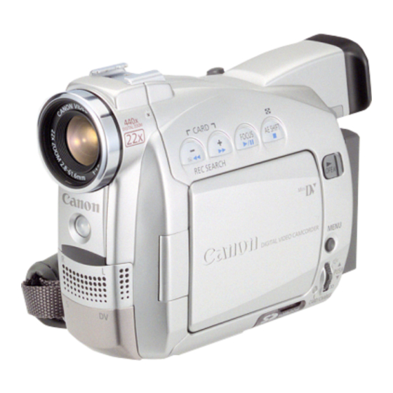
- Page 12 ZR70 MC A, ZR65 MC A, ZR60 A CHAPTER 1. GENERAL DESCRIPTION OF PRODUCT G External View Fig. 1-1...
-
Page 13: Technical Explanation
(both ZR65 MC A and ZR60 A). The front terminal cover is now finished with metallic paint on all models (ZR70 MC A, ZR65 MC A, and ZR60 A) for a more deluxe look. 2-1-2 Variation... -
Page 14: Dmc Iii Digital Mechanism Chassis
2-2-1 Improved Quality The DMC I and DMC II digital mechanism chassis, which formed the core of previous Canon camcorder models, were developed in 1997 and 1999, respectively. They helped make those camcorders more compact. In particular, as the excellent image quality and reliability of Canon camcorders has come to be highly evaluated by the marketplace in recent years, the number of units manufactured has been increasing substantially. -
Page 15: Dmc Iii Slide In/Out Status
ZR70 MC A, ZR65 MC A, ZR60 A CHAPTER 1. GENERAL DESCRIPTION OF PRODUCT 2-2-3 DMC III Slide In/Out Status Slide in status Slide out status 56mm 73mm 1-12... -
Page 16: Direct Print (Canon Camera Direct Correspondence Printer)
2-3 Direct Print (Canon Camera Direct Correspondence Printer) By connecting the Canon BJ F890PD or BJ 895PD or BJ 535PD camera direct correspondence printer to the product (ZR70 MC A), the user can print still images stored on an SD memory card or MultiMediaCard without using a PC. -
Page 17: Performance And Functions
ZR70 MC A, ZR65 MC A, ZR60 A CHAPTER 1. GENERAL DESCRIPTION OF PRODUCT 3. Performance and Functions ZR70 MC A, ZR65 MC A, ZR60 A 1 Type VTR- integrated camera 2 Recording system Rotating two- head helical scan azimuth recording... - Page 18 10 mm (from lens front) 5-2-10 Filter diameter 30.5 mm P0.5 5-2-11 Accessory lens, filter Can use WD- 30.5, TL- 30.6, FS- 30.5U, or WA- 30.5 (WA- 30.5 is supplied with ZR70 MC A model only.) 5-2-12 Lens hood None 5-2-13 Lens cap Included;...
- Page 19 Full Auto mode, Auto mode, Sports mode, Portrait mode, Spotlight mode, Surf (Sand) & Snow mode, Low Light mode, Low Light + mode (ZR70 MC A: Card and Camera modes only), Night mode, Super Night mode (Super Night mode is ZR70 MC A only)
- Page 20 Card mix : A mixture of included sample images, images recorded to a card, and camera motion video is displayed. (ZR70 MC A, ZR65 MC A model only) 5-11-1 Fader (tape recording only) Audio synchronized fader Auto fade (JAPAN models: White Fade;...
- Page 21 ZR70 MC A, ZR65 MC A, ZR60 A CHAPTER 1. GENERAL DESCRIPTION OF PRODUCT 5-12 Built-in microphone Stereo (using electret condenser microphone) Stereo provided by 2 nondirectional microphones and electric circuit 5-12-1 Wind screen function Provided, with ON/OFF switch (selected by menu; built-in microphone only)
- Page 22 6-6-4 Microphone terminal Impedance 5 KΩ or higher −57dBv (using 600 Ω microphone) Level 6-6-5 USB port (ZR70 MC A, ZR65 MC A only) Conforms to USB 1.1. 6-7 Output signals 6-7-1 DV terminal Complies with IEEE1394– AV/ C protocol 6-7-2 AV terminal a.
- Page 23 ZR70 MC A, ZR65 MC A, ZR60 A CHAPTER 1. GENERAL DESCRIPTION OF PRODUCT 6-8 Memory card system (ZR70 MC A, ZR65 MC A only) 6-8-1 Types of memory cards used SD memory card, Multimedia card. 6-8-2 Recordable image types and image quality...
- Page 24 ZR70 MC A, ZR65 MC A, ZR60 A CHAPTER 1. GENERAL DESCRIPTION OF PRODUCT XGA 1024(H) × 768(V) pixels 6-8-4 Still image recorded image size Number of recorded still images (SDC-8M) Super Fine mode 14 (file size per image: approx. 440 kb) Fine mode 20 (file size per image: approx.
- Page 25 Compatible with DPOF printer settings (image and number of copies). 6-10-1 Printable images On the ZR70 MC A, ZR65 MC A, still image files stored on an SD memory card or MultiMediaCard only. 6-10-2 Print format Single-image printing.
- Page 26 CHAPTER 1. GENERAL DESCRIPTION OF PRODUCT 6-11-11 Playback zoom When viewing images recorded on tape or card (ZR70 MC A, ZR65 MC A only,still images only), moving the Zoom lever to the Telephoto side causes the image being displayed to appear at 2x magnification.
-
Page 27: System Diagram (Common To All Models)
ZR70 MC A, ZR65 MC A, ZR60 A CHAPTER 1. GENERAL DESCRIPTION OF PRODUCT 4. System Diagram (Common to all Models) WS-20 Wrist Strap ZR70 MC SS-800 Shoulder Strap WA-30.5Wide Attachment ZR70 MC ZR65 MC WL-D79 Wireless BP-500 Series Controller Battery Pack WD-30.5Wide-... -
Page 28: Overview Of Viewfinder / Lcd Panel Displays
ZR70 MC A, ZR65 MC A, ZR60 A CHAPTER 1. GENERAL DESCRIPTION OF PRODUCT 5. Overview of Viewfinder / LCD Panel Displays 5-1 Camera Mode MENU INDICATION NORTH AMERICA MODEL REMARKS Camera mode Zoom display (displayed for approx. four seconds after zooming) Optical zooming 88 ×... - Page 29 Low light mode is selected Night mode is selected Super Night mode is selected ZR70 MC A only Program AE mode menu Super Night mode is for ZR70 MC A only. Tape counter display Time code display Not entered Zero Set Memory...
- Page 30 ZR70 MC A, ZR65 MC A, ZR60 A CHAPTER 1. GENERAL DESCRIPTION OF PRODUCT MENU INDICATION NORTH AMERICA MODEL REMARKS Timer display Remaining tape display At end of tape Not entered Tape warning display Flashes red Other No display Focus mode display...
- Page 31 ZR70 MC A, ZR65 MC A, ZR60 A CHAPTER 1. GENERAL DESCRIPTION OF PRODUCT MENU INDICATION NORTH AMERICA MODEL REMARKS Shutter speed display 1/60 sec. 1/100 sec. 1/250 sec. 1/500 sec. 1/1000 sec. 1/2000 sec. Auto No display White balance display...
- Page 32 ZR70 MC A, ZR65 MC A, ZR60 A CHAPTER 1. GENERAL DESCRIPTION OF PRODUCT MENU INDICATION NORTH AMERICA MODEL REMARKS Digital feature display Fade Tigger Wipe (horizontal) Corner Wipe Jump Flip Puzzle Zigzag Beam Tide Black and White Sepia Mosaic...
- Page 33 ZR70 MC A, ZR65 MC A, ZR60 A CHAPTER 1. GENERAL DESCRIPTION OF PRODUCT Digital Feature selection Press the “D.E. SEL” button in Camera mode, VCR mode, or Card Recording mode. The line where the cursor is located in the menu is surrounded with a turquoise frame.
- Page 34 ZR70 MC A, ZR65 MC A, ZR60 A CHAPTER 1. GENERAL DESCRIPTION OF PRODUCT MENU INDICATION NORTH AMERICA MODEL REMARKS Wind screen display Wind screen ON Wind screen OFF No display Time and date display When time and date are not set...
-
Page 35: Vcr Mode
ZR70 MC A, ZR65 MC A, ZR60 A CHAPTER 1. GENERAL DESCRIPTION OF PRODUCT 5-2 VCR Mode MENU INDICATION NORTH AMERICA MODEL REMARKS VCR mode Audio output display 12-bit Stereo 1 is selected 12-bit Stereo 2 is selected 12-bit Mix 1:1 is selected... - Page 36 ZR70 MC A, ZR65 MC A, ZR60 A CHAPTER 1. GENERAL DESCRIPTION OF PRODUCT MENU INDICATION NORTH AMERICA MODEL REMARKS Still image playback Reverse still image playback Frame reverse playback Slow reverse playback 1× SP reverse playback 2× SP reverse playback...
- Page 37 ZR70 MC A, ZR65 MC A, ZR60 A CHAPTER 1. GENERAL DESCRIPTION OF PRODUCT MENU INDICATION NORTH AMERICA MODEL REMARKS Remote sensor code display Same as during Camera mode Battery warning display Same as during Camera mode Condensation warning display...
- Page 38 ZR70 MC A, ZR65 MC A, ZR60 A CHAPTER 1. GENERAL DESCRIPTION OF PRODUCT MENU INDICATION NORTH AMERICA MODEL REMARKS Time display Time setting is selected Not entered Time and time setting are selected Not entered Date display Not entered...
-
Page 39: Card/Camera Mode (Zr70 Mc A, Zr65 Mc A Only)
ZR70 MC A, ZR65 MC A, ZR60 A CHAPTER 1. GENERAL DESCRIPTION OF PRODUCT 5-3 Card/Camera Mode (ZR70 MC A, ZR65 MC A only) MENU INDICATION NORTH AMERICA MODEL REMARKS Card / Camera mode Zoom display Same as during Camera mode... - Page 40 ZR70 MC A, ZR65 MC A, ZR60 A CHAPTER 1. GENERAL DESCRIPTION OF PRODUCT MENU INDICATION NORTH AMERICA MODEL REMARKS Card free space display No card (flashes red) Accidental erasure protection 9999 or more images can be recorded 99 images can be recorded...
- Page 41 ZR70 MC A, ZR65 MC A, ZR60 A CHAPTER 1. GENERAL DESCRIPTION OF PRODUCT MENU INDICATION NORTH AMERICA MODEL REMARKS Digital feature display Same as during Camera mode (but with no fader function) Time and date display Same as during Camera mode...
-
Page 42: Card Playback Mode (Zr70 Mc A, Zr65 Mc A Only)
ZR70 MC A, ZR65 MC A, ZR60 A CHAPTER 1. GENERAL DESCRIPTION OF PRODUCT 5-4 Card Playback Mode (ZR70 MC A, ZR65 MC A only) MENU INDICATION NORTH AMERICA MODEL REMARKS Card play mode Slideshow display DPOP designation display Protect mark display... - Page 43 ZR70 MC A, ZR65 MC A, ZR60 A CHAPTER 1. GENERAL DESCRIPTION OF PRODUCT MENU INDICATION NORTH AMERICA MODEL REMARKS Image number display No card Flashes red Checking number of images recorded on card 0 recorded images of 99 recorded images...
-
Page 44: Menu Display
ZR70 MC A, ZR65 MC A, ZR60 A CHAPTER 1. GENERAL DESCRIPTION OF PRODUCT 5-5 Menu Display Camera mode, VCR mode, Card/Camera mode, and Card Playback mode are provided in the menu display. Camera Mode MAIN MENU ITEM SUB MENU ITEM... - Page 45 ZR70 MC A, ZR65 MC A, ZR60 A CHAPTER 1. GENERAL DESCRIPTION OF PRODUCT MAIN MENU ITEM SUB MENU ITEM SETTINGS DEFAULT BACKUP DISP. SET UP DEMO MODE Lithium battery RETURN SYSTEM BUTTON LIGHT *3 Lithium battery PUSH ON LIGHT COLOR *3...
- Page 46 PATTERN3 RETURN CLOSE MENU *1 : ZR70 MC A, ZR65 MC A model only. *2 : BEEP, BRIGHTNESS, MIRROR, and D/T DISPLAY information is not displayed on screens other than the menu screen. *3 : ZR70 MC A model only.
- Page 47 ZR70 MC A, ZR65 MC A, ZR60 A CHAPTER 1. GENERAL DESCRIPTION OF PRODUCT VCR Mode MAIN MENU ITEM SUB MENU ITEM SETTINGS DEFAULT BACKUP VCR SET UP REC MODE Lithium battery AV/PHONES Lithium battery PHONES DV OUT Reset when power is...
- Page 48 ZR70 MC A, ZR65 MC A, ZR60 A CHAPTER 1. GENERAL DESCRIPTION OF PRODUCT MAIN MENU ITEM SUB MENU ITEM SETTINGS DEFAULT BACKUP SYSTEM BUTTON LIGHT *4 Lithium battery PUSH ON LIGHT COLOR *4 GREEN GREEN Lithium battery ORANGE BLUE...
- Page 49 *1 : BRIGHTNESS, 6 SEC. DATE, OUTPUT CH, and BEEP information is not displayed on screens other than the menu screen. *2 : ZR70 MC A, ZR65 MC A model only. *3 : Displayed only when DATA CODE is ON on screens other than the menu screen.
- Page 50 ZR70 MC A, ZR65 MC A, ZR60 A CHAPTER 1. GENERAL DESCRIPTION OF PRODUCT Card Camera Mode (ZR70 MC A, ZR65 MC A only) MAIN MENU ITEM SUB MENU ITEM SETTINGS DEFAULT BACKUP CAM. SET UP SHUTTER AUTO AUTO Lithium battery...
- Page 51 ZR70 MC A, ZR65 MC A, ZR60 A CHAPTER 1. GENERAL DESCRIPTION OF PRODUCT MAIN MENU ITEM SUB MENU ITEM SETTINGS DEFAULT BACKUP SYSTEM T. ZONE/DST *2 LONDON N.Y. Lithium battery LONDON PARIS PARIS · · · · · ·...
- Page 52 ZR70 MC A, ZR65 MC A, ZR60 A CHAPTER 1. GENERAL DESCRIPTION OF PRODUCT Card Playback Mode (Card/VCR Mode) (ZR70 MC A, ZR65 MC A only) MAIN MENU ITEM SUB MENU ITEM SETTINGS DEFAULT BACKUP CARD OPER. COPY [ Go to the Copy execution screen...
- Page 53 ZR70 MC A, ZR65 MC A, ZR60 A CHAPTER 1. GENERAL DESCRIPTION OF PRODUCT MAIN MENU ITEM SUB MENU ITEM SETTINGS DEFAULT BACKUP SYSTEM T. ZONE/DST *4 LONDON N.Y. Lithium battery LONDON PARIS PARIS · · · · · ·...
- Page 54 ZR70 MC A, ZR65 MC A, ZR60 A CHAPTER 1. GENERAL DESCRIPTION OF PRODUCT MAIN MENU ITEM SUB MENU ITEM SETTINGS DEFAULT BACKUP MY CAMERA CREATE START-UP Go to the Startup screen creation screen SEL. S-UP IMG NO PICTURE CANON LOGO...
-
Page 55: Card-Related Screen Displays
ZR70 MC A, ZR65 MC A, ZR60 A CHAPTER 1. GENERAL DESCRIPTION OF PRODUCT 5-6 Card-Related Screen Displays MENU INDICATION NORTH AMERICA MODEL REMARKS Slideshow screen Index screen Image protect screen Print order screen 1-52... - Page 56 ZR70 MC A, ZR65 MC A, ZR60 A CHAPTER 1. GENERAL DESCRIPTION OF PRODUCT MENU INDICATION NORTH AMERICA MODEL REMARKS Copy screen Copy ( ) selection screen Copy ( ) execution screen Copy ( ) selection screen Copy ( ) execution screen...
- Page 57 ZR70 MC A, ZR65 MC A, ZR60 A CHAPTER 1. GENERAL DESCRIPTION OF PRODUCT MENU INDICATION NORTH AMERICA MODEL REMARKS Image erase screen Image erase selection screen Erasing one image Warning: Erasing in progress Erasing all images 1-54...
- Page 58 ZR70 MC A, ZR65 MC A, ZR60 A CHAPTER 1. GENERAL DESCRIPTION OF PRODUCT MENU INDICATION NORTH AMERICA MODEL REMARKS Format screen Format execution confirmation screen Format execution screen 1-55...
- Page 59 ZR70 MC A, ZR65 MC A, ZR60 A CHAPTER 1. GENERAL DESCRIPTION OF PRODUCT MENU INDICATION NORTH AMERICA MODEL REMARKS Card mix selection screen Mix type setting screen Animation type setting screen Mix level setting screen 1-56...
- Page 60 ZR70 MC A, ZR65 MC A, ZR60 A CHAPTER 1. GENERAL DESCRIPTION OF PRODUCT MENU INDICATION NORTH AMERICA MODEL REMARKS Stitch assist screen My camera settings My camera settings screen Startup image creation screen Select recording position 1-57...
- Page 61 ZR70 MC A, ZR65 MC A, ZR60 A CHAPTER 1. GENERAL DESCRIPTION OF PRODUCT MENU INDICATION NORTH AMERICA MODEL REMARKS My camera settings Record execution confirmation Message during image creation Startup image selection screen Shutter sound selection screen Startup sound selection screen...
- Page 62 ZR70 MC A, ZR65 MC A, ZR60 A CHAPTER 1. GENERAL DESCRIPTION OF PRODUCT MENU INDICATION NORTH AMERICA MODEL REMARKS My camera settings Start/stop selection screen Self-timer sound selection screen PC connection screen displays USB connection IEEE1394 connection 1-59...
-
Page 63: Direct Print Setting Screen
ZR70 MC A, ZR65 MC A, ZR60 A CHAPTER 1. GENERAL DESCRIPTION OF PRODUCT 5-7 Direct Print Setting Screen MENU INDICATION NORTH AMERICA MODEL Direct print setting screen Direct print setting initial screen Print selection screen L Size L Size... - Page 64 ZR70 MC A, ZR65 MC A, ZR60 A CHAPTER 1. GENERAL DESCRIPTION OF PRODUCT MENU INDICATION NORTH AMERICA MODEL Direct print setting screen Number of copies setting screen L Size Bordered Style Copies Print Cancel L Size L Size Bordered...
- Page 65 ZR70 MC A, ZR65 MC A, ZR60 A CHAPTER 1. GENERAL DESCRIPTION OF PRODUCT MENU INDICATION NORTH AMERICA MODEL Direct print setting screen Style setting screen L Size Borderless Style Copies Print Cancel Go to the style setting screen using MENU buttons...
-
Page 66: Print
ZR70 MC A, ZR65 MC A, ZR60 A CHAPTER 1. GENERAL DESCRIPTION OF PRODUCT 5-8 Print MENU INDICATION NORTH AMERICA MODEL OK screen L Size L Size 9999 9999 Borderless Borderless Style Print all marketed images Now Printing (1/9999) Cancel... -
Page 67: Warning Displays
ZR70 MC A, ZR65 MC A, ZR60 A CHAPTER 1. GENERAL DESCRIPTION OF PRODUCT 5-9 Warning Displays COPYRIGHT PROTECTED PLAYBACK IS RESTRICTED • When copy-protected tape is played. COPYRIGHT PROTECTED DUBBING RESTRICTED • When copy protection information is detected during DV input or LINE input, or when the signal output from the television or VCR is garbled during analog input. - Page 68 CHAPTER 1. GENERAL DESCRIPTION OF PRODUCT CARD ERROR • When a card error occurs and data cannot be recorded on the card (for ZR70 MC A, ZR65 MC A model). CARD FULL • When the card is full (for ZR70 MC A, ZR65 MC A model).
-
Page 69: Backing Up Various Data
- - - - Time and date settings (auto date) 2003. 1.1 12:00 AM Menu cursor position Very top Time code - - - - Mix balance (ZR70 MC A, ZR65 MC A only) Center Headphone volume Center Speaker volume Center Mechanical errors... -
Page 70: Backup Conditions Related To Switch Operation
* CAM : Camera mode only *CD : Card Recording mode only (ZR70 MC A, ZR65 MC A only) * Independent : Independent backup for Card/Camera mode, Camera mode, and VCR mode The card recording still image selection in Card Mix (Card Mix standby state) is not backed up when the power is turned off. -
Page 71: Switching The Power Switch To A Different Position
G Card Playback mode (ZR70 MC A, ZR65 MC A only) On screen ON/OFF Reset (set to OFF) Data code display ON/OFF Reset (set to OFF) G Card Playback mode menu item selection (ZR70 MC A, ZR65 MC A only) Remote control code setting Backup Recording mode setting Backup... -
Page 72: Switching Camera Modes/Switching Program Ae Modes
Backup * CAM : Camera mode only *CD : Card Recording mode only (ZR70 MC A, ZR65 MC A only) * Independent : Independent backup for Card Recording mode, Camera mode, and VCR mode : When is set again, “Auto” is set. -
Page 73: Other Features
× * : ZR70 MC A, ZR65 MC A only Super Night mode is limited to the ZR70 MC A. 7-2 On Screen • Turn ON/OFF of the On-screen function is performed through the infrared remote controller or from the menu. -
Page 74: Headphones And Speaker
ZR70 MC A, ZR65 MC A, ZR60 A CHAPTER 1. GENERAL DESCRIPTION OF PRODUCT 7-3 Headphones and Speaker • In Camera mode and Camera/Card mode, the speaker is OFF. • The speakers are on during normal card playback in the VCR mode. The Multi switch is used to adjust the volume. -
Page 75: Confirmation Beep
ZR70 MC A, ZR65 MC A, ZR60 A CHAPTER 1. GENERAL DESCRIPTION OF PRODUCT 7-8 Confirmation Beep In the following cases, beep melodically. Mode Sound Power ON When tape with erase protection is loaded (Camera mode) BEEP BEEP BEEP When EJECT cover is opened all the way (even when power is OFF) -
Page 76: Using Analog Line Recording And Dv Recording
ZR70 MC A, ZR65 MC A, ZR60 A CHAPTER 1. GENERAL DESCRIPTION OF PRODUCT 7-9 Using Analog Line Recording and DV Recording (1) Move the power switch to the VCR position and the Tape/Card switch to the TAPE. If a cassette has been inserted it will be stopped. -
Page 77: Support For Analog Signal I/O Copyright Protection Signals
ZR70 MC A, ZR65 MC A, ZR60 A CHAPTER 1. GENERAL DESCRIPTION OF PRODUCT 7-10 Support for Analog Signal I/O Copyright Protection Signals (1) Detection of copyright protection signals added to input signals • Detected copyright protection signals: Pseudo-synch pulses and CGMSA (Copy Generation Management System for analog) signals •... -
Page 78: Audio Dubbing
ZR70 MC A, ZR65 MC A, ZR60 A CHAPTER 1. GENERAL DESCRIPTION OF PRODUCT 7-12 Audio Dubbing 7-12-1 Tapes to which Audio Dubbing can be Added Audio dubbing can only be added to tapes with 1 2-bit/SP recording (other than 4-channel simultaneous recording). The camcorder switches to Stop mode if audio dubbing is attempted on other tapes. -
Page 79: Av Insert (Not Available On Pal Models)
ZR70 MC A, ZR65 MC A, ZR60 A CHAPTER 1. GENERAL DESCRIPTION OF PRODUCT 7-13 AV Insert (Not available on PAL Models) In AV Insert mode, an ITI (Insert and Track Information) area is kept and audio, video, and sub-codes are overwritten. -
Page 80: Analog/Digital Signal Conversion
ZR70 MC A, ZR65 MC A, ZR60 A CHAPTER 1. GENERAL DESCRIPTION OF PRODUCT 7-14 Analog/Digital Signal Conversion This function can be used as an A/D conversion function for inputting an analog AV signal from an analog device to a PC. - Page 81 CHAPTER 2. TECHNICAL DESCRIPTION CONTENTS 1. P.C.B. Functions ------------------------------------------------------------------------------------------------------------------------------ 2-1 2. Power Supply Circuit ------------------------------------------------------------------------------------------------------------------------ 2-3 2-1 Startup of Power Supply ------------------------------------------------------------------------------------------------------------- 2-3 2-2 Power Fuses ---------------------------------------------------------------------------------------------------------------------------- 2-5 2-3 Power Supply Circuits ---------------------------------------------------------------------------------------------------------------- 2-6 3. Built-in Charger Circuit ---------------------------------------------------------------------------------------------------------------------- 2-7 3-1 Outline ---------------------------------------------------------------------------------------------------------------------------------- 2-7 3-2 Operation at Charging ---------------------------------------------------------------------------------------------------------------- 2-8 3-2-1 Conditions To Start Charging --------------------------------------------------------------------------------------------- 2-8...
-
Page 82: Functions
ZR70 MC A, ZR65 MC A, ZR60 A CHAPTER 2. TECHNICAL DESCRIPTION 1. P.C.B. Functions (1) MAIN P.C.B. System-Control Section • IC100 MODE MI-COM System control • IC200 BACK UP MODE MI-COM resetting • IC103 RESET Detects a DC JACK voltage to the MODE MI-COM. - Page 83 ZR70 MC A, ZR65 MC A, ZR60 A CHAPTER 2. TECHNICAL DESCRIPTION (5) CVF P.C.B. Signal transfer from CAC P.C.B. to CVF-LCD, back-light LED turn-on. (6) JACK P.C.B. AV, MIC, S JACK, USB interface, Remoto control signal receiver sensor, white LED.
-
Page 84: Power Supply Circuit
ZR70 MC A, ZR65 MC A, ZR60 A CHAPTER 2. TECHNICAL DESCRIPTION 2. Power Supply Circuit <Outline> In this product, a novel type of power supply system including a compact adapter (CA-570) is adopted for enhancement of cost performance and power savings. - Page 85 ZR70 MC A, ZR65 MC A, ZR60 A CHAPTER 2. TECHNICAL DESCRIPTION • Backup Lithium Battery LI3V power from the lithium battery is input to pin 3 of the IC102, and it is output from pin 12 as power to the MODE microcom- puter.
-
Page 86: Power Fuses
ZR70 MC A, ZR65 MC A, ZR60 A CHAPTER 2. TECHNICAL DESCRIPTION 2-2 Power Fuses MAIN P.C.B. CN3201 FU3201 DC + UNREG 1 FU3203 MECHA UNREG FU3204 DC/DC UNREG MODE FU3205 MI-COM SHOE UNREG * ZR70MC A Only FU3202 P5 + VTR UNREG... -
Page 87: Power Supply Circuits
ZR70 MC A, ZR65 MC A, ZR60 A CHAPTER 2. TECHNICAL DESCRIPTION 2-3 Power Supply Circuits Figure 2-3 shows the power supply circuits. The ON/OFF condition of each power supply voltage is controlled by the VTR ON signals output from the MODE MI-COM. -
Page 88: Built-In Charger Circuit
ZR70 MC A, ZR65 MC A, ZR60 A CHAPTER 2. TECHNICAL DESCRIPTION 3. Built-in Charger Circuit MAIN P.C.B. P.C.B. DC JACK DET CN3201 DC J SW IC103 RESET JACK Q1805 Q1803 INIT CHG2 BATT AD INIT CHG1 Q1804 IC100 MODE MI-COM. -
Page 89: Operation At Charging
ZR70 MC A, ZR65 MC A, ZR60 A CHAPTER 2. TECHNICAL DESCRIPTION 3-2 Operation at Charging 3-2-1 Conditions To Start Charging When the following conditions are satisfied, the MODE MI-COM (IC100) to start charging. Conditions Detection Source of detection Main unit power is turned OFF. -
Page 90: Progress Of Charging
ZR70 MC A, ZR65 MC A, ZR60 A CHAPTER 2. TECHNICAL DESCRIPTION 3-2-2 Progress of Charging When the conditions described in 3-2-1 are satisfied, the MODE MI-COM starts charging according to the specifications in Fig.2-5. The charging current in quick charge can be restricted by CA-570. -
Page 91: Signal Processing Circuit
ZR70 MC A, ZR65 MC A, ZR60 A CHAPTER 2. TECHNICAL DESCRIPTION 4. Signal Processing Circuit 4-1 Outline of Signal Processing Circuit Figure 2-6 shows the entire block diagram of the signal processing circuit and the flow of video and audio signals. -
Page 92: Camera/Card Signal Processing
ZR70 MC A, ZR65 MC A, ZR60 A CHAPTER 2. TECHNICAL DESCRIPTION 4-2 Camera/Card Signal Processing 4-2-1 Camera Motion Picture Recording 64 Mbit SDRAM IC1101 32 bit SDRAM IF Deformation, CDS/ Synthesis Drawing AGC/ COMP VIC3 proc resize REND IC1001... -
Page 93: Card Motion Picture Recording
ZR70 MC A, ZR65 MC A, ZR60 A CHAPTER 2. TECHNICAL DESCRIPTION 4-2-3 Card Motion Picture Recording 64 Mbit SDRAM IC1101 32 bit SDRAM IF MI-COM YCC 1 YCC 2 Deformation, Synthesis CDS/ VIC3 Drawing COMP AGC/ IC2301 REND proc... -
Page 94: Recorder Signal Processing
ZR70 MC A, ZR65 MC A, ZR60 A CHAPTER 2. TECHNICAL DESCRIPTION 4-3 Recorder Signal Processing VIC BLOCK DIF BLOCK IC2303 SDRAM SDRAM INTERFACE INTERFACE TERMINAL VIDEO HEAD A DATA VIDEO REC/PB IC2000 IC1102 COMPRESSION B DATA INTERFACE PROCESS VRP2 MACS /DEMOD. -
Page 95: Audio Signal Flow
ZR70 MC A, ZR65 MC A, ZR60 A CHAPTER 2. TECHNICAL DESCRIPTION 4-4 Audio Signal Flow IC2301 IC2000 IC1102 MACS VIC3 VRP2 HEAD PHONE IC801 REC/ AIF3 MEM IF CARD IF JACK HEAD BEEP SDRAM CARD FR MI-COM. IC802 BEEP SPEAKER −... -
Page 96: System Control, Servo
ZR70 MC A, ZR65 MC A, ZR60 A CHAPTER 2. TECHNICAL DESCRIPTION 5. System Control, Servo 5-1 Outline of System Control, Servo Figure 2-12 shows the overall configuration of the system control & servo circuit, plus the flow of data. System control is per- formed by the FR MI-COM (IC2301) and MODE MI-COM (IC100) on MAIN P.C.B. -
Page 97: Major Functions Of Each Microcomputer
ZR70 MC A, ZR65 MC A, ZR60 A CHAPTER 2. TECHNICAL DESCRIPTION 5-2 Major Functions of Each Microcomputer (1) FR MI-COM (IC2301 : VIC3) The FR MI-COM, as the nucleus of the system, carries out control of mode transition plus mechanism control through communi- cation with MODE MI-COM. -
Page 98: Servo Control
ZR70 MC A, ZR65 MC A, ZR60 A CHAPTER 2. TECHNICAL DESCRIPTION 5-3 Servo Control Servo control is carried out by the VIC3 (VIC and FR MI-COM). The FR MI-COM is used for servo control of motor ON/OFF and rotational direction, and the VIC is used to output rotational speed and phase control signals. More specifically in terms of signal flow, the VIC detects the FG/PG and PB-RF signals from the motor, and sends the detected signal information to the FR MI-COM. -
Page 99: Personal Computer Connection Mode (Usb)
ZR70 MC A, ZR65 MC A, ZR60 A CHAPTER 2. TECHNICAL DESCRIPTION 5-4 Personal Computer Connection Mode (USB) IC1101 SDRAM IC1102 MACS IC1002 Still Picture IC1001 MEMORY TG/CDS Signal CARD AGC/AD Processing Card camera mode of signal flow MI-COM CONTROLER... -
Page 100: Error Detection
ZR70 MC A, ZR65 MC A, ZR60 A CHAPTER 2. TECHNICAL DESCRIPTION 5-5 Error Detection If an abnormality has been occurred in any rotation drive system (drum, capstan, reel, loading), a relevant mode enters. The LCD indicates “PLEASE UNLOAD THE CASSETTE” and blinks “EJECT”. - Page 101 CHAPTER 3. INFORMATION FOR REPAIR · SERVICE HINTS CONTENTS 1. List of Maintenance Tools and Supplies --------------------------------------------------------------------------------------------------- 3-1 1-1 List of Maintenance Tools ----------------------------------------------------------------------------------------------------------- 3-1 1-2 List of Supplies ------------------------------------------------------------------------------------------------------------------------ 3-1 2. Setting ------------------------------------------------------------------------------------------------------------------------------------------- 3-2 2-1 Setting A -------------------------------------------------------------------------------------------------------------------------------- 3-2 2-2 Setting B -------------------------------------------------------------------------------------------------------------------------------- 3-3 3.
-
Page 102: List Of Maintenance Tools And Supplies
ZR70 MC A, ZR65 MC A, ZR60 A CHAPTER 3. INFORMATION FOR REPAIR · SERVICE HINTS 1. List of Maintenance Tools and Supplies 1-1 List of Maintenance Tools Item Name Item Number Purpose Remarks Alignment T ape, (Color bar master/NT SC) -
Page 103: Setting
ZR70 MC A, ZR65 MC A, ZR60 A CHAPTER 3. INFORMATION FOR REPAIR · SERVICE HINTS 2. Setting (1) Adjustments other than DMC-III : Perform adjustments in the product state. (2) Tracking adjustment (DMC-III) and Envelope check : Perform them with the Setting A. -
Page 104: Setting B
ZR70 MC A, ZR65 MC A, ZR60 A CHAPTER 3. INFORMATION FOR REPAIR · SERVICE HINTS 2-2 Setting B (1) Remove the FRONT COVER, REAR COVER, LEFT COVER UNIT, RIGHT COVER UNIT and JACK P.C.B. referring to “Chapter 4-1: Disassembling and Reassembling”. -
Page 105: Service Modes
ZR70 MC A, ZR65 MC A, ZR60 A CHAPTER 3. INFORMATION FOR REPAIR · SERVICE HINTS 3. Service Modes 3-1 Outline (1) The service mode in this equipment uses the wireless remote controller. (To be used in remote control code 2) (2) For changeover to the service mode, a dedicated tool (CASSETTE, SERVICE MODE: DY9-1386-000) is required in addition to the wireless remote controller. -
Page 106: How To Operate Wireless Remote Controller In Service Mode
ZR70 MC A, ZR65 MC A, ZR60 A CHAPTER 3. INFORMATION FOR REPAIR · SERVICE HINTS 3-3 How to Operate Wireless Remote Controller in Service Mode (1) To use the wireless remote controller in the service mode, set it at Remote controller code 2. -
Page 107: Indication In Service Mode
ZR70 MC A, ZR65 MC A, ZR60 A CHAPTER 3. INFORMATION FOR REPAIR · SERVICE HINTS 3-4 Indication in Service Mode Shown below are the indications in the service mode. Fig. 3-7 Indicates that the service mode is currently selected. (“SERV”) MODE : Indicates the MODE currently selected. -
Page 108: Description Of Service Modes
ZR70 MC A, ZR65 MC A, ZR60 A CHAPTER 3. INFORMATION FOR REPAIR · SERVICE HINTS 4. Description of Service Modes 4-1 Error Rate <Generals> (1) A VIDEO error rate (VIDEO + AUDIO) and an AUDIO error rate can be checked. -
Page 109: Mechanical Error Indication
ZR70 MC A, ZR65 MC A, ZR60 A CHAPTER 3. INFORMATION FOR REPAIR · SERVICE HINTS 4-2 Mechanical Error Indication <Outline> (1) On occurrence of a mechanical error, the conditions of the error can be checked in the service mode. (Normal indication mode and... -
Page 110: Mechanical Error Analysis Mode
ZR70 MC A, ZR65 MC A, ZR60 A CHAPTER 3. INFORMATION FOR REPAIR · SERVICE HINTS 4-2-2 Mechanical Error Analysis Mode 1. Address of the sequence that was under execution in the event of an error. (information of the control status.) 2. -
Page 111: Cleaning Mode
ZR70 MC A, ZR65 MC A, ZR60 A CHAPTER 3. INFORMATION FOR REPAIR · SERVICE HINTS 4-3 Cleaning Mode When cleaning the head with hard-type cleaning tape (DY9-1384-000), set up the cleaning mode according to the procedure given below. Note : After head cleaning, be sure to restore the settings to normal. -
Page 112: Checking The Lens Resetting
ZR70 MC A, ZR65 MC A, ZR60 A CHAPTER 3. INFORMATION FOR REPAIR · SERVICE HINTS 4-5 Checking the Lens Resetting <Generals> (1) Setting the address according to the table below allows to check whether the lens resetting is ended or not. -
Page 113: Mode Mi-Com A/D Port
ZR70 MC A, ZR65 MC A, ZR60 A CHAPTER 3. INFORMATION FOR REPAIR · SERVICE HINTS 4-6-2 MODE MI-COM A/D Port ST EP NAME DESCRIPT ION CS Function ADDR AD DAT A ( 00 〜 FF ) REMARK Batt A/D... -
Page 114: Service Hints
ZR70 MC A, ZR65 MC A, ZR60 A CHAPTER 3. INFORMATION FOR REPAIR · SERVICE HINTS 5. Service Hints 5-1 Arrangement of Circuit Boards The printed circuit boards are arranged as shown below. OPERATION KEY EJECT P.C.B. CCD P.C.B. CVF P.C.B. -
Page 115: Location Of Main Elements
ZR70 MC A, ZR65 MC A, ZR60 A CHAPTER 3. INFORMATION FOR REPAIR · SERVICE HINTS 5-2 Location of Main Elements MAIN P.C.B. IC103 IC100 RESET MODE MI-COM IC301 MOTOR DRIVE IC300 FU1801 OPE AMP FU3205 IC102 FU3201 BACKUP FU3202... - Page 116 ZR70 MC A, ZR65 MC A, ZR60 A CHAPTER 3. INFORMATION FOR REPAIR · SERVICE HINTS CAC P.C.B. IC1701 IC1002 IC1001 IC1202 MOTOR DRIVE TG/CDS/AGC/AD V-DRIVER IRIS DRIVE IC1502 IC1501 EEPROM EVF DRIVER JACK P.C.B. LCD P.C.B. IC1601 IC4201 P SENSOR GYRO...
-
Page 117: Current Consumption Check
ZR70 MC A, ZR65 MC A, ZR60 A CHAPTER 3. INFORMATION FOR REPAIR · SERVICE HINTS 5-3 Current Consumption Check The following table shows the specified value of current consumption in each status. Measurement condition : Product status, camera auto mode(AF,IS OFF), LCD ON (Approx. 0.1A each smaller in case of CVF) Preset voltage : 7.4V... -
Page 118: Trouble Shooting
ZR70 MC A, ZR65 MC A, ZR60 A CHAPTER 3. INFORMATION FOR REPAIR · SERVICE HINTS 6. Trouble Shooting To detect the failure part for repair, if any, use the following hints and check points. 6-1 Power Supply <Hints> When the power source is attached, the unit enters the standby mode in the following sequences. -
Page 119: Camera Picture Faulty
ZR70 MC A, ZR65 MC A, ZR60 A CHAPTER 3. INFORMATION FOR REPAIR · SERVICE HINTS 6-2 Camera Picture Faulty <Hints> A flow of camera picture (EE) is as below. CCD → CAC P.C.B. → MAIN P.C.B. (MACS → VIC3→VIF2) → JACK P.C.B. -
Page 120: Faulty Of Playback Picture
ZR70 MC A, ZR65 MC A, ZR60 A CHAPTER 3. INFORMATION FOR REPAIR · SERVICE HINTS 6-3 Faulty of Playback Picture <Hints> In the DV, degradation of picture quality normally appears on the screen as block noise. This is because, if an error occurs exceeding the ability of the error correction circuit, the block by block information of pictures is not played back properly and thus complemented by the previous picture information. -
Page 121: Startup Window Setting
ZR70 MC A, ZR65 MC A, ZR60 A CHAPTER 3. INFORMATION FOR REPAIR · SERVICE HINTS 6-4 Startup Window Setting The startup window (user setting) contains a default image* at shipment from the factory. If any other image is written over the default image, it is deleted completely. -
Page 122: Mechanical Error Applicability Table
ZR70 MC A, ZR65 MC A, ZR60 A CHAPTER 3. INFORMATION FOR REPAIR · SERVICE HINTS 7. Mechanical Error Applicability Table The address data in the mechanical error applicability table varies depending on the version of the FR MI-COM. Check the MI-COM version, and refer to the mechanical error applicability table relevant to the MI-COM version. - Page 123 ZR70 MC A, ZR65 MC A, ZR60 A CHAPTER 3. INFORMATION FOR REPAIR · SERVICE HINTS Mecha Error Address Label Sequence Drum Caps SReel TReel Loading DEW 0AD172 MechaEjectToStop0139 Changeover to blank search end 0AD218 MechaEjectToStop0140 Changeover to blank search end...
- Page 124 ZR70 MC A, ZR65 MC A, ZR60 A CHAPTER 3. INFORMATION FOR REPAIR · SERVICE HINTS Mecha Error Address Label Sequence Drum Caps SReel TReel Loading DEW 0B1DBC MechaPlayToFwd1x PLAY Changeover : capstan × 2 → × 1 0B1E1E MechaFwd2xToFwd1x Changeover : Still →...
- Page 125 ZR70 MC A, ZR65 MC A, ZR60 A CHAPTER 3. INFORMATION FOR REPAIR · SERVICE HINTS Mecha Error Address Label Sequence Drum Caps SReel TReel Loading DEW Changeover : Still → 1/10 slow RVS 0B5A0A MechaStillRvsToSlow10Rvs 0B5E48 MechaShuttleFwdLoop Edit search FWD Changeover : Still →...
- Page 126 ZR70 MC A, ZR65 MC A, ZR60 A CHAPTER 3. INFORMATION FOR REPAIR · SERVICE HINTS Mecha Error Address Label Sequence Drum Caps SReel TReel Loading DEW 0B9BC0 MechaPhotoSearchRvs0030 Photo search RVS start 0B9C34 MechaPhotoSearchRvs0040 Photo search RVS start 0B9CD0...
- Page 127 ZR70 MC A, ZR65 MC A, ZR60 A CHAPTER 3. INFORMATION FOR REPAIR · SERVICE HINTS Mecha Error Address Label Sequence Drum Caps SReel TReel Loading DEW 0BDA60 MechaRecPauseToAVIPause Changeover to AV insert pause 0BDAAE MechaAVIPauseLoop AV insert pause 0BDAE6...
- Page 128 ZR70 MC A, ZR65 MC A, ZR60 A CHAPTER 3. INFORMATION FOR REPAIR · SERVICE HINTS Mechanical Error Applicability Table (for MAIN program version “1224” in FR MI-COM) Mecha Error Address Label Sequence Drum Caps SReel TReel Loading DEW 0A9130...
- Page 129 ZR70 MC A, ZR65 MC A, ZR60 A CHAPTER 3. INFORMATION FOR REPAIR · SERVICE HINTS Mecha Error Address Label Sequence Drum Caps SReel TReel Loading DEW Changeover : REW → STOP 0AD73A MechaRewToStop Changeover : Rec Pause → STOP...
- Page 130 ZR70 MC A, ZR65 MC A, ZR60 A CHAPTER 3. INFORMATION FOR REPAIR · SERVICE HINTS Mecha Error Address Label Sequence Drum Caps SReel TReel Loading DEW Changeover : Still → capstan × 1 0B253C MechaStillRvsToFwd1x0010 Changeover : Still → capstan × 1...
- Page 131 ZR70 MC A, ZR65 MC A, ZR60 A CHAPTER 3. INFORMATION FOR REPAIR · SERVICE HINTS Mecha Error Address Label Sequence Drum Caps SReel TReel Loading DEW Changeover : Still → Edit search RVS 0B61C2 MechaStillRvsToShuttleRvs 0B63E4 MechaSEFStillLoop Edit search FWD still Edit search FWD →...
- Page 132 ZR70 MC A, ZR65 MC A, ZR60 A CHAPTER 3. INFORMATION FOR REPAIR · SERVICE HINTS Mecha Error Address Label Sequence Drum Caps SReel TReel Loading DEW 0B9DDE MechaPhotoSearchRvs0080 Photo search RVS 0B9E8C MechaPhotoSearchRvs0100 Changeover to photo search RVS end...
- Page 133 ZR70 MC A, ZR65 MC A, ZR60 A CHAPTER 3. INFORMATION FOR REPAIR · SERVICE HINTS Mecha Error Address Label Sequence Drum Caps SReel TReel Loading DEW 0BE034 ABSRvsSlw Reverse frame feed Changeover: Still RVS → Still FWS 0BE0D4 TurnRvsToFwd Changeover: Still RVS →...
- Page 134 CHAPTER 4. DISASSEMBLING ADJUSTMENT CONTENTS 1. Disassembling and Reassembling ---------------------------------------------------------------------------------------------------------- 4-1 1-1 Disassembling / Reassembling Flowchart ----------------------------------------------------------------------------------------- 4-1 1-2 Separation of Front Unit ------------------------------------------------------------------------------------------------------------- 4-2 1-3 Separation of Accessory Shoe ------------------------------------------------------------------------------------------------------- 4-3 1-4 Separation of Right Cover Unit ----------------------------------------------------------------------------------------------------- 4-4 1-5 Separation of Rear Cover Unit ------------------------------------------------------------------------------------------------------ 4-5 1-6 Separation of Jack P.C.B ------------------------------------------------------------------------------------------------------------- 4-6 1-7 Separation of Left Cover Unit ------------------------------------------------------------------------------------------------------- 4-7...
- Page 135 2. Adjustment Procedures ---------------------------------------------------------------------------------------------------------------------- 4-33 2-1 Adjustment Items in Part Replacement -------------------------------------------------------------------------------------------- 4-33 2-2 AF Section Adjustment -------------------------------------------------------------------------------------------------------------- 4-34 2-2-1 CZ Automatic Adjustment ----------------------------------------------------------------------------------------------- 4-34 2-2-2 Cam Correction (AUTO) ------------------------------------------------------------------------------------------------- 4-35 2-3 IS Section Adjustment --------------------------------------------------------------------------------------------------------------- 4-36 2-3-1 GYRO OFFSET Adjustment -------------------------------------------------------------------------------------------- 4-36 2-3-2 GYRO GAIN Adjustment ------------------------------------------------------------------------------------------------ 4-36 2-3-3 Virtual EEPROM and Flash Memory Writing ------------------------------------------------------------------------ 4-37 2-4 Camera Section Adjustment -------------------------------------------------------------------------------------------------------- 4-38...
-
Page 136: Disassembling And Reassembling
ZR70 MC A, ZR65 MC A, ZR60 A CHAPTER 4. DISASSEMBLING ADJUSTMENT 1. Disassembling and Reassembling Notes : (1) When replacing the flat cable with a new one, allow it to remain folded the same as the original part. (2) The flat cable has a contact orientation to be engaged with the connector. Refer to the instructions in the disassembly procedure diagram and interconnection diagram for boards. -
Page 137: Separation Of Front Unit
ZR70 MC A, ZR65 MC A, ZR60 A CHAPTER 4. DISASSEMBLING ADJUSTMENT 1-2 Separation of Front Unit (1) Open the cassette cover, F Jack Cover and L Jack Cover and remove seven screws (b × 5, c × 1, d × 1). -
Page 138: Separation Of Accessory Shoe
ZR70 MC A, ZR65 MC A, ZR60 A CHAPTER 4. DISASSEMBLING ADJUSTMENT 1-3 Separation of Accessory Shoe (1) Remove four screws (a × 4) and detach the Accessory Shoe. (1) - a Accessory Shoe Metal M1.7 Flat Head Screw Fig. 4-2... -
Page 139: Separation Of Right Cover Unit
(1) Push the CN990 and CN1502 sufficiently so as to prevent them from being pinched in the part A. (2) Since the Shaft may come out easily, take care not to lose the Shaft. (Only for ZR70 MC A,ZR65 MC A) Before using the Card Cover and Shaft supplied for repair service, remove their protection sheet and shaft-dropping preventive tape. -
Page 140: Separation Of Rear Cover Unit
ZR70 MC A, ZR65 MC A, ZR60 A CHAPTER 4. DISASSEMBLING ADJUSTMENT 1-5 Separation of Rear Cover Unit (1) Remove three screws (d × 3), disconnect the CN1501, CN3201 and CN3202 and detach Rear Cover Unit. CN1501 CN3202 CN3201 4.5mm... -
Page 141: Separation Of Jack P.c.b
ZR70 MC A, ZR65 MC A, ZR60 A CHAPTER 4. DISASSEMBLING ADJUSTMENT 1-6 Separation of Jack P.C.B (1) Remove two screws (b × 2), disconnect the CN5, CN2101 and CN6 and detach the Jack P.C.B. (2) Open the Cassette Cover and remove one screw (c × 1). Pull the part A to this side while lifting it, disengage the two claw parts B and detach the C Lock Plate Unit. -
Page 142: Separation Of Left Cover Unit
ZR70 MC A, ZR65 MC A, ZR60 A CHAPTER 4. DISASSEMBLING ADJUSTMENT 1-7 Separation of Left Cover Unit (1) Remove three screws (b × 3), disconnect the CN101 and detach the Left Cover Unit. Left Cover Unit (1) - b... -
Page 143: Separation Of Camera Unit
(1) Remove two screws (b × 2), disconnect the CN891, CN1001 and CN1201 and detach the Camera Unit. Note : The CN891 connector should be disconnected in the ZR70 MC A only. In the ZR65 MC A, ZR60 A, it is not required to disconnect the CN891 connector since the shoe connector Ass’y and its relevant flexible cable are... -
Page 144: Separation Of Main And Cac P.c.b.'s
ZR70 MC A, ZR65 MC A, ZR60 A CHAPTER 4. DISASSEMBLING ADJUSTMENT 1-9 Separation of Main and CAC P.C.B.'s (1) Remove one screw (b × 1), disconnect the CN1101 and CN1002 (B to B) and detach the CAC P.C.B. (2) Remove three screws (b × 3), disconnect the CN300, CN301, CN302, CN303, and CN2000 and detach the MAIN P.C.B. -
Page 145: Separation Of Recorder Holder
ZR70 MC A, ZR65 MC A, ZR60 A CHAPTER 4. DISASSEMBLING ADJUSTMENT 1-10 Separation of Recorder Holder (1) Remove three screws (e × 3) and detach the Recorder Holder, vibration isolating Rubber and Spring. Note : When placing the DMC III mechanical unit with the recorder holder removed, be sure to orient the drum side upward. -
Page 146: Separation Of Front Cover Unit
ZR70 MC A, ZR65 MC A, ZR60 A CHAPTER 4. DISASSEMBLING ADJUSTMENT 1-11 Separation of Front Cover Unit (1) Remove three screws (d × 3) and detach the Lens Cover, L Jack Cover and F Jack Cover. (2) Remove two screws (d × 2) and detach the Microphone Cover, Rubber, Microphone Ass'y and Microphone Shield. -
Page 147: Disassembling Of Left Cover Unit
(1) Remove four screws (d × 4) and detach the Operation Key Ass'y. (2) Remove the Shaft and detach the Hand Strap. (3) Remove one screw (d × 1) and detach the Change Plate and Change Knob. (Only for ZR70 MC A, ZR65 MC A) <Note on Reassembling>... - Page 148 ZR70 MC A, ZR65 MC A, ZR60 A CHAPTER 4. DISASSEMBLING ADJUSTMENT 1-13 Disassembling of Left Cover Unit - 2 (1) Remove two screws (f × 2) and detach the GND Plate, Cushion, Speaker Holder and Speaker Ass'y. (2) Remove one screw (i × 1) and detach the EJECT P.C.B.
-
Page 149: Disassembling Of Left Cover Unit
ZR70 MC A, ZR65 MC A, ZR60 A CHAPTER 4. DISASSEMBLING ADJUSTMENT 1-14 Disassembling of Left Cover Unit - 3 (1) Remove four screws (i × 4) and detach the Cassette Cover while taking care of the two claw parts. -
Page 150: Separation Of Lcd Unit
ZR70 MC A, ZR65 MC A, ZR60 A CHAPTER 4. DISASSEMBLING ADJUSTMENT 1-15 Separation of LCD Unit (1) Disconnect the CN101. (2) Open and turn the LCD Unit, remove four screws (c × 2, d × 2) and detach the LCD Unit. -
Page 151: Disassembling Of Right Cover Unit
ZR70 MC A, ZR65 MC A, ZR60 A CHAPTER 4. DISASSEMBLING ADJUSTMENT 1-16 Disassembling of Right Cover Unit - 1 (1) Detach the Lithium Battery Cover. (2) Remove four screws (h × 4), disconnect the CN4002 and detach the Card P.C.B. and AP Knob. -
Page 152: Disassembling Of Right Cover Unit
ZR70 MC A, ZR65 MC A, ZR60 A CHAPTER 4. DISASSEMBLING ADJUSTMENT 1-17 Disassembling of Right Cover Unit - 2 (1) Remove the Cushion. (2) Remove two screws (g × 1, h × 1), disconnect the CN100 and detach the R-Key Backlight Ass'y and R-Key Backlight Holder. -
Page 153: Disassembling Of Right Cover Unit
(2) Treat the R-Key P.C.B. flexible cable as illustrated below. When using the part supplied for repair service, bend the flexible cable part A to 45°. (3) Attach UL Tape at the position indicated in the figure shown below. (Only for ZR70 MC A) Note on Reassembling (3) - Page 154 ZR70 MC A, ZR65 MC A, ZR60 A CHAPTER 4. DISASSEMBLING ADJUSTMENT 1-19 Disassembling of Right Cover Unit - 4 (1) Remove one screw (j × 1) and detach the LCD Lock Holder, LCD Lock, LCD Open Knob, LCD Lifter, and Spring 1and 2.
-
Page 155: Disassembling Of Lcd Unit
ZR70 MC A, ZR65 MC A, ZR60 A CHAPTER 4. DISASSEMBLING ADJUSTMENT 1-20 Disassembling of LCD Unit - 1 (1) Remove three screws (b × 3) and detach the LCD Top Cover. Note : When detaching the LCD Top Cover, be careful of the claw parts A and B inside the cover. - Page 156 ZR70 MC A, ZR65 MC A, ZR60 A CHAPTER 4. DISASSEMBLING ADJUSTMENT 1-21 Disassembling of LCD Unit - 2 (1) Detach the LCD Bottom Cover and Bottom Cover Sheet. (2) Detach the soldered parts A and B, disconnect the CN903, remove one screw (b × 1) and detach the LCD P.C.B.
-
Page 157: Separation Of Cvf Unit
(1) Attach the CVF-CAC FPC as illustrated below. Secure it with UL Tape. (2) On approx. 5,000 units in the initial unit only (ZR70 MC A : 1,000 units, ZR65 MC A : 2,000 units, ZR60 A : 2,000 units) : When attaching each of the screws, tighten it securely until it does not turn further without applying a new adhesive. -
Page 158: Separation Of Rear Cover Unit
ZR70 MC A, ZR65 MC A, ZR60 A CHAPTER 4. DISASSEMBLING ADJUSTMENT 1-23 Separation of Rear Cover Unit (1) Remove four screws (h × 4) and detach the Battery Terminal Ass'y and GND Plate. (2) Remove one screw (h × 1) and detach the DC P.C.B. -
Page 159: Disassembling Of Cvf Unit
ZR70 MC A, ZR65 MC A, ZR60 A CHAPTER 4. DISASSEMBLING ADJUSTMENT 1-24 Disassembling of CVF Unit - 1 (1) Detach the Dust Cover, remove two screws (b × 2) and detach the CVF Bottom Cover. (2) Remove one screw (d × 1), disengage the holes on CVF-CAC FPC from the protruded parts A and draw out the finder while taking care not to damage the CVF-CAC FPC. - Page 160 ZR70 MC A, ZR65 MC A, ZR60 A CHAPTER 4. DISASSEMBLING ADJUSTMENT 1-25 Disassembling of CVF Unit - 2 (1) Remove two screws (d × 2) and detach the Eyepiece, CVF Lens Holder, CVF Knob, Rubber and Lens Holder. (2) Detach the two claw parts A and detach the Lens.
-
Page 161: Disassembling Of Cvf Unit
ZR70 MC A, ZR65 MC A, ZR60 A CHAPTER 4. DISASSEMBLING ADJUSTMENT 1-26 Disassembling of CVF Unit - 3 (1) Disconnect the CN4101 and detach the CVF-CAC FPC. (2) Detach the three claw parts A and detach the components from the CVF P.C.B. to the Mask Plate. -
Page 162: Disassembling Of Camera Unit
ZR70 MC A, ZR65 MC A, ZR60 A CHAPTER 4. DISASSEMBLING ADJUSTMENT 1-27 Disassembling of Camera Unit - 1 (1) Remove one screw (k × 1) and detach the Accessory Shoe. Note : Lift the hooked parts of the two Dowels diagonally and detach the Shoe Base backward. - Page 163 ZR70 MC A, ZR65 MC A, ZR60 A CHAPTER 4. DISASSEMBLING ADJUSTMENT 1-28 Disassembling of Camera Unit - 2 (1) Remove two screws (m × 2) and detach the CCD P.C.B., CCD Ass'y, Rubber part and Low-Pass Filter. (2) Detach the soldered part A and detach the CCD P.C.B. and CCD Ass'y.
-
Page 164: Disassembling Of Lens Unit
ZR70 MC A, ZR65 MC A, ZR60 A CHAPTER 4. DISASSEMBLING ADJUSTMENT 1-29 Disassembling of Lens Unit (1) Remove the Lens Rubber part and three screws (m × 3). Demount the Front Lens Ass'y. (2) Remove six screws (d × 4, n × 2) and solder (α). Demount the PZ Motor, AF Motor, IG Meter Ass'y, PZ Shaft, and AF Shaft. -
Page 165: List Of Screws Used
ZR70 MC A, ZR65 MC A, ZR60 A CHAPTER 4. DISASSEMBLING ADJUSTMENT 1-30 List of Screws Used PARTS NO. REMARKS ILLUST PARTS NO. REMARKS ILLUST Flat Head Screw XA1-3170-507 XA1-7170-257 M1.7-2.5mm (Metal) 2.5mm M1.7-5.0mm (Metal) Self Tap XA1-7170-307 M1.7-3.0mm (Metal) XA4-9170-557 5.5mm... -
Page 166: List Of Disassembly Photos
ZR70 MC A, ZR65 MC A, ZR60 A CHAPTER 4. DISASSEMBLING ADJUSTMENT 1-31 List of Disassembly Photos Front Side Right Side Recorder/Camera Unit Camera Unit-1 Camera Unit-2 Front Cover Unit 4-31... - Page 167 ZR70 MC A, ZR65 MC A, ZR60 A CHAPTER 4. DISASSEMBLING ADJUSTMENT Left Cover Unit Right Cover Unit Rear Cover Unit 4-32...
-
Page 168: Adjustment Procedures
ZR70 MC A, ZR65 MC A, ZR60 A CHAPTER 4. DISASSEMBLING ADJUSTMENT 2. Adjustment Procedures 2-1 Adjustment Items in Part Replacement After replacement of major parts, carry out adjustment referring to the table shown below. Note that the following table shows minimum required adjustments to be performed after replacing any major part. -
Page 169: Af Section Adjustment
ZR70 MC A, ZR65 MC A, ZR60 A CHAPTER 4. DISASSEMBLING ADJUSTMENT 2-2 AF Section Adjustment Note) (1) The sections 2-2-1 : CZ automatic adjustment and 2-2-2 : Cam correction (AUTO) must be executed consecutively. If they are performed independently, the sufficient performance cannot be obtained. -
Page 170: Cam Correction (Auto)
ZR70 MC A, ZR65 MC A, ZR60 A CHAPTER 4. DISASSEMBLING ADJUSTMENT 2-2-2 Cam Correction (AUTO) CHART CZ adjustment chart SPEC. Automatic adjustment Procedure) (1) Quit the service mode, and turn power OFF/ON. (2) Perform the cam correction by following the table below. -
Page 171: Is Section Adjustment
ZR70 MC A, ZR65 MC A, ZR60 A CHAPTER 4. DISASSEMBLING ADJUSTMENT 2-3 IS Section Adjustment Note) (1) Perform the IS adjustment after machine is re-assembled to a product status. (2) Prepare a tripod or stable work bench. (3) Each of the adjustment data (2-3-1 and 2) becomes valid when 2-3-3 data writing is made. After completion of each adjustment, be sure to carry out 2-3-3 before turning power OFF. -
Page 172: Virtual Eeprom And Flash Memory Writing
ZR70 MC A, ZR65 MC A, ZR60 A CHAPTER 4. DISASSEMBLING ADJUSTMENT 2-3-3 Virtual EEPROM and Flash Memory Writing SPEC. Automatic writing Procedure) (1) According to the table shown below, write adjustment data (2-3-1 and 2) into the virtual EEPROM and flash memory. -
Page 173: Camera Section Adjustment
ZR70 MC A, ZR65 MC A, ZR60 A CHAPTER 4. DISASSEMBLING ADJUSTMENT 2-4 Camera Section Adjustment Notes) (1) Each adjustment data (2-4-1 to 2-4-5) becomes effective after it is written into the DATA as mentioned in 2-4-6. If power must be turned OFF/ON during each adjustment, be sure to perform the DATA write procedure as mentioned in 2-4-6. -
Page 174: Color Balance Adjustment
ZR70 MC A, ZR65 MC A, ZR60 A CHAPTER 4. DISASSEMBLING ADJUSTMENT 2-4-3 Color Balance Adjustment CHART Lightbox (5600°K), and color bar chart (white area at the left side) M.EQ. Vectorscope TP/TRIG. VIDEO OUT R : × 1.7 (ratio to burst) 90°, Ye : × 1.0 (ratio to burst) 195°... -
Page 175: Wb Adjustment (3)
ZR70 MC A, ZR65 MC A, ZR60 A CHAPTER 4. DISASSEMBLING ADJUSTMENT 2-4-5 WB Adjustment (3) CHART Light box (5600°K) SPEC. Automatic adjustment Procedure) (1) Referring to the table shown below, carry out WB adjustment (3). ST EP PROCEDURE MONIT OR... -
Page 176: Ccd Pixel Missing Compensation
ZR70 MC A, ZR65 MC A, ZR60 A CHAPTER 4. DISASSEMBLING ADJUSTMENT 2-5 CCD Pixel Missing Compensation Notes) (1) Perform this adjustment only if a void pixel is found on the CCD. (2) Before starting this adjustment, turn power on for 30 minutes. -
Page 177: Color Balance Check
ZR70 MC A, ZR65 MC A, ZR60 A CHAPTER 4. DISASSEMBLING ADJUSTMENT 2-6 Color Balance Check Preparation) (1) Carry out this correction in the product state. (2) Adjustment Conditions Program AE : AUTO : OFF Image stabilizer : OFF Demo mode... -
Page 178: Recorder Section Adjustment
(1) Referring to the table shown below, carry out the setting for destination market place. ST EP PROCEDURE MONIT OR Microcomputer operation CS Function MD ADDR DT 1) Make the setting shown at right. 0064 ZR70 MC A / ZR65 MC A / ZR60 A 2) Perform storing. Data writing ↑ ↑ ↑ ↑... -
Page 179: Y Level Adjustment
ZR70 MC A, ZR65 MC A, ZR60 A CHAPTER 4. DISASSEMBLING ADJUSTMENT 2-7-2 Y LEVEL Adjustment TP/TRIG. VIDEO OUT M. EQ. Oscilloscope SPEC. 980 ± 20 [mV] Procedure) (1) Select the card VTR mode. (2) Referring to the table shown below, carry out Y level adjustment. -
Page 180: C Level Adjustment
ZR70 MC A, ZR65 MC A, ZR60 A CHAPTER 4. DISASSEMBLING ADJUSTMENT 2-7-3 C LEVEL Adjustment TP/TRIG. VIDEO OUT M. EQ. Oscilloscope SPEC. 710 ± 20 [mV] Procedure) (1) Select the card VTR mode. (2) Referring to the table shown below, carry out C level adjustment. -
Page 181: Swp Adjustment
ZR70 MC A, ZR65 MC A, ZR60 A CHAPTER 4. DISASSEMBLING ADJUSTMENT 2-7-5 SWP Adjustment MODE Playback of color bar master (DY9-1380-000) SPEC. Automatic adjustment Procedure) (1) While playing back the color bar master, carry out SWP automatic adjustment referring to the table shown below. -
Page 182: Battery Voltage Drop Adjustment
ZR70 MC A, ZR65 MC A, ZR60 A CHAPTER 4. DISASSEMBLING ADJUSTMENT 2-7-9 Battery Voltage Drop Adjustment MODE During camera recording in product condition (AF : OFF, LCD PANEL : ON) SPEC. Power supply voltage: 5.85 ± 0.02 [V] Note) (1) Perform the adjustment after 4sec of recording start. -
Page 183: Tape Path Adjustment
ZR70 MC A, ZR65 MC A, ZR60 A CHAPTER 4. DISASSEMBLING ADJUSTMENT 2-8 Tape Path Adjustment Note) (1) For tape path adjustment, the service mode setting is necessary. For the details of setting procedure, refer to the DMC III Section. - Page 184 ZR70 MC A, ZR65 MC A, ZR60 A CHAPTER 4. DISASSEMBLING ADJUSTMENT Copy the chart on a transparent film. Trim and attach the transparent chart on a vectorscope display. Color balance adjustment chart ZR70 MC A FR 1st MI-COM only...
- Page 185 ZR70 MC A, ZR65 MC A, ZR60 A CHAPTER 4. DISASSEMBLING ADJUSTMENT Copy the chart on a transparent film. Trim and attach the transparent chart on a vectorscope display. Color balance adjustment chart ZR70 MC A NTSC ZR65 MC A...
- Page 186 CHAPTER 5. PARTS LIST CONTENTS EXPLODED VIEWS Casing Parts Section ------------------------------------------------------------------------------------------------------------------------ 5-2 Front Cover Unit Section ------------------------------------------------------------------------------------------------------------------ 5-4 Left Cover Unit Section-1 ----------------------------------------------------------------------------------------------------------------- 5-6 Left Cover Unit Section-2 ----------------------------------------------------------------------------------------------------------------- 5-8 Right Cover Unit Section-1 -------------------------------------------------------------------------------------------------------------- 5-10 Right Cover Unit Section-2 -------------------------------------------------------------------------------------------------------------- 5-12 LCD Unit Section -------------------------------------------------------------------------------------------------------------------------- 5-14 Rear Cover Unit Section ------------------------------------------------------------------------------------------------------------------ 5-16 CVF Unit Section -------------------------------------------------------------------------------------------------------------------------- 5-18...
- Page 187 CAUTION 1. Especially critical parts in the power circuit block should not be replaced with other marks. Critical parts are marked with in this electrical parts list.
-
Page 188: Casing Parts Section
ZR70 MC A, ZR65 MC A, ZR60 A Casing Parts Section LEFT COVER REAR COVER UNIT UNIT ×4 ×3 FRONT COVER UNIT ×3 CAMERA/ LENS/ ×2 RECORDER UNIT ×2 RIGHT COVER UNIT... - Page 189 ZR70 MC A, ZR65 MC A, ZR60 A MECHANICAL PARTS SYMBOL PART NO. CLASS Q’TY DESCRIPTION REMARKS XA1-7170-307 000 SCREW XA1-3170-507 000 SCREW DA2-0436-000 000 SHOE, ACCESSORY D52-0220-000 000 CAP, LENS XA4-9170-457 000 SCREW XA1-7170-407 000 SCREW DA3-0299-000 000 CUSHION DY1-8532-000 000 PCB ASS’Y, JACK...
-
Page 190: Front Cover Unit Section
ZR70 MC A, ZR65 MC A, ZR60 A Front Cover Unit Section ×2 ×3... - Page 191 ZR70 MC A, ZR65 MC A, ZR60 A MECHANICAL PARTS SYMBOL PART NO. CLASS Q’TY DESCRIPTION REMARKS DA3-0274-000 000 COVER, L JACK ZR70 MC A,ZR65 MC A NEW DA3-0281-000 000 COVER, L JACK ZR60 A DY1-8537-000 000 COVER ASS’Y, FRONT...
-
Page 192: Left Cover Unit Section-1
ZR70 MC A, ZR65 MC A, ZR60 A Left Cover Unit Section-1 ×2 ×2 ×2 *1 : ZR70 MC A, ZR65 MC A ONLY... - Page 193 ZR70 MC A, ZR65 MC A, ZR60 A MECHANICAL PARTS SYMBOL PART NO. CLASS Q’TY DESCRIPTION REMARKS DA3-0236-000 000 KNOB, CHANGE ZR70 MC A,ZR65 MC A NEW DA3-0249-000 000 PLATE, CHANGE ZR70 MC A,ZR65 MC A NEW XA4-9170-457 000 5(4)
-
Page 194: Left Cover Unit Section-2
ZR70 MC A, ZR65 MC A, ZR60 A Left Cover Unit Section-2 ×2 ×2 ×3... - Page 195 ZR70 MC A, ZR65 MC A, ZR60 A MECHANICAL PARTS SYMBOL PART NO. CLASS Q’TY DESCRIPTION REMARKS DA3-0240-000 000 STRAP, HAND XA1-7170-257 000 SCREW DA3-0226-000 000 COVER, CASSETTE DA3-0225-000 000 COVER, LEFT ZR70 MC A DA3-0294-000 000 COVER, LEFT ZR65 MC A...
-
Page 196: Right Cover Unit Section-1
ZR70 MC A, ZR65 MC A, ZR60 A Right Cover Unit Section-1 RIGHT COVER UNIT ×2 LCD UNIT ×2 *1 : ZR70 MC A, ZR65 MC A ONLY 5-10... - Page 197 ZR70 MC A, ZR65 MC A, ZR60 A MECHANICAL PARTS SYMBOL PART NO. CLASS Q’TY DESCRIPTION REMARKS DA2-1650-000 000 CUSHION ZR70 MC A DA3-0332-000 000 CUSHION ZR65 MC A,ZR60 A DA3-0185-000 000 COVER, LI BATT DA3-0180-000 000 COVER, CARD ZR70 MC A,ZR65 MC A NEW...
-
Page 198: Right Cover Unit Section-2
ZR70 MC A, ZR65 MC A, ZR60 A Right Cover Unit Section-2 ×2 ×2 ×4 ×2 *1 : ZR70 MC A ONLY *2 : ZR70 MC A, ZR65 MC A ONLY 5-12... - Page 199 ZR70 MC A, ZR65 MC A, ZR60 A MECHANICAL PARTS SYMBOL PART NO. CLASS Q’TY DESCRIPTION REMARKS XA4-9170-557 000 SCREW XA1-7170-207 000 5(4) SCREW *( )ZR65 MC A,ZR60 A DA3-0181-000 000 LOCK, CARD COVER ZR70 MC A,ZR65 MC A NEW DY1-8533-000 000 PCB ASS’Y, R-KEY...
-
Page 200: Lcd Unit Section
ZR70 MC A, ZR65 MC A, ZR60 A LCD Unit Section ×2 ×3 5-14... - Page 201 ZR70 MC A, ZR65 MC A, ZR60 A MECHANICAL PARTS SYMBOL PART NO. CLASS Q’TY DESCRIPTION REMARKS XA1-7170-307 000 SCREW DA3-0263-000 000 COVER, LCD TOP ZR70 MC A DA3-0284-000 000 COVER, LCD TOP ZR65 MC A DA3-0287-000 000 COVER, LCD TOP...
-
Page 202: Rear Cover Unit Section
ZR70 MC A, ZR65 MC A, ZR60 A Rear Cover Unit Section CVF Unit ×4 ×3 5-16... - Page 203 ZR70 MC A, ZR65 MC A, ZR60 A MECHANICAL PARTS SYMBOL PART NO. CLASS Q’TY DESCRIPTION REMARKS XA4-9170-407 000 SCREW DF1-5006-000 000 BATTERY TERMINAL ASS’Y DA3-0250-000 000 COVER, REAR DY1-8514-000 000 PCB ASS’Y, DC DA3-0251-000 000 LEVER, BATTERY EJECT DA3-0256-000 000...
-
Page 204: Cvf Unit Section
ZR70 MC A, ZR65 MC A, ZR60 A CVF Unit Section ×2 ×2 ×2 5-18... - Page 205 ZR70 MC A, ZR65 MC A, ZR60 A MECHANICAL PARTS SYMBOL PART NO. CLASS Q’TY DESCRIPTION REMARKS DA3-0215-000 000 COVER, DUST ZR70 MC A,ZR65 MC A NEW DA3-0223-000 000 COVER, DUST ZR60 A DA3-0206-000 000 COVER, CVF TOP ZR70 MC A,ZR65 MC A NEW...
-
Page 206: Recorder Unit Section
ZR70 MC A, ZR65 MC A, ZR60 A Recorder Unit Section CAMERA/LENS ×2 UNIT ×3 ×3 ×3 5-20... - Page 207 ZR70 MC A, ZR65 MC A, ZR60 A MECHANICAL PARTS SYMBOL PART NO. CLASS Q’TY DESCRIPTION REMARKS DY1-8499-000 000 RECORDER UNIT, DMC III DA1-9903-000 000 LABEL, S CHASSIS DA3-0160-000 000 HOLDER, RECORDER DA1-9779-000 000 RUBBER, INSULATION DA2-0314-000 000 SPRING, PLATE...
-
Page 208: Camera Unit Section
ZR70 MC A, ZR65 MC A, ZR60 A Camera Unit Section ×2 LENS UNIT ×3 *1, 2 : ZR70 MC A ONLY ×3 5-22... - Page 209 ZR70 MC A, ZR65 MC A, ZR60 A MECHANICAL PARTS SYMBOL PART NO. CLASS Q’TY DESCRIPTION REMARKS DG1-7296-000 000 SHOE CONNECTOR ASS’Y ZR70 MC A DA2-1645-000 000 SPACER, SHOE ZR65 MC A,ZR60 A XA9-1349-000 000 SCREW DA2-1622-000 000 RUBBER, INSULATION...
-
Page 210: Lens Unit Section
ZR70 MC A, ZR65 MC A, ZR60 A Lens Unit Section ×2 ×2 ×3 5-24... - Page 211 ZR70 MC A, ZR65 MC A, ZR60 A MECHANICAL PARTS SYMBOL PART NO. CLASS Q’TY DESCRIPTION REMARKS XA4-9170-607 000 SCREW YH8-0122-000 000 IG METER UNIT YG9-6000-000 000 SHAFT, PZ YG9-5999-000 000 SHAFT, AF YG1-0154-000 000 MOTOR, AF XA4-9170-457 000 SCREW...
-
Page 212: Mechanical Chassis Section-1
DMC III Mechanical Chassis Section-1 ×3 5-26... - Page 213 DMC III MECHANICAL PARTS SYMBOL PART NO. CLASS Q’TY DESCRIPTION REMARKS DG1-4506-000 000 COMPARTMENT ASS’Y, CASSETTE XA1-7140-147 000 SCREW, CROSS-RECESS, PH DA2-2138-000 000 SCREW DY1-8500-000 000 DRUM ASS’Y DA2-2139-000 000 WASHER DF1-1703-000 000 IDLER ASS’Y DA2-2116-000 000 SPRING, COIL (DRUM) DA2-2115-000 000 SCREW DY1-8501-000 000...
-
Page 214: Mechanical Chassis Section-2
DMC III Mechanical Chassis Section-2 5-28... - Page 215 DMC III MECHANICAL PARTS SYMBOL PART NO. CLASS Q’TY DESCRIPTION REMARKS DA2-0645-000 000 WASHER DG1-4504-000 000 REEL ASS’Y, S DS1-0193-000 000 SPRING, COIL (TENSION) DF1-1693-000 000 BRAKE ASS’Y, TENSION DF1-1694-000 000 RELEASE ASS’Y, TENSION DA2-2139-000 000 WASHER DF1-1704-000 000 BRAKE ASS’Y, S DS1-0199-000 000 SPRING, COIL (S BRAKE) DG1-4505-000 000...
-
Page 216: Mechanical Chassis Section-3
DMC III Mechanical Chassis Section-3 ×2 ×3 ×2 5-30... - Page 217 DMC III MECHANICAL PARTS SYMBOL PART NO. CLASS Q’TY DESCRIPTION REMARKS DG1-4502-000 000 MOTOR ASS’Y, LOADING DA2-2261-000 000 SCREW DG1-4497-000 000 GUIDE RAIL ASS’Y DF1-1687-000 000 ROLLER ASS’Y, GUIDE S DF1-1688-000 000 ROLLER ASS’Y, GUIDE T DA2-0780-000 000 SCREW DF1-1686-000 000 DRUM BASE ASS’Y DA2-2259-000 000 SCREW...
-
Page 218: Mechanical Chassis Section-4
DMC III Mechanical Chassis Section-4 5-32... - Page 219 DMC III MECHANICAL PARTS SYMBOL PART NO. CLASS Q’TY DESCRIPTION REMARKS DA2-2191-000 000 LEVER, CAM XA1-7140-147 000 SCREW, CROSS-RECESS, PH DA2-2196-000 000 BELT, TIMING DA2-2197-000 000 GEAR, PULLEY DA2-2190-000 000 GEAR, CONNECT DA2-2140-000 000 WASHER DA2-2188-000 000 GEAR, WHEEL DA2-2139-000 000 WASHER DA2-2195-000 000 GEAR, CAPSTAN...
-
Page 220: Accessory Section-1
ZR70 MC A, ZR65 MC A, ZR60 A Accessory Section-1 CG-570 N.S. (Product available) CA-570 N.S. (Product available) CB-570 N.S. (Product available) SDC-8M N.S. (Commercially availabel. Make copy sample pictures if necessary.) PLUG TYPE N.S. (Product available) WL-D79A WL-D80A BP-511/512/522/535... - Page 221 ZR70 MC A, ZR65 MC A, ZR60 A MECHANICAL PARTS SYMBOL PART NO. CLASS Q’TY DESCRIPTION REMARKS DY1-8531-000 000 DC CABLE D82-0642-000 000 CORD, AC(A) PLUG TYPE A D55-0170-000 000 WIDE ATTACHMENT ZR70 MC A DY1-8242-000 000 COVER, TERMINAL BP-511(BROWN)
-
Page 222: Accessory Section-2
ZR70 MC A, ZR65 MC A, ZR60 A Accessory Section-2 N.S. (Product available) N.S. (Product available) WD-30.5 DM-50 N.S. (Product available) TL-30.5 IFC-300PCU N.S. (Product available) N.S. (Product available) VL-3 N.S. (Product available) FS-30.5 SS-800 5-36... - Page 223 ZR70 MC A, ZR65 MC A, ZR60 A MECHANICAL PARTS SYMBOL PART NO. CLASS Q’TY DESCRIPTION REMARKS DY1-8246-000 000 WIND SCREEN, FRONT DY1-8247-000 000 WIND SCREEN, REAR DY1-8245-000 000 LAMP, HAROGEN DY4-4764-000 000 CAP, CONVERTER(FRONT) DY4-4765-000 000 CAP, CONVERTER(REAR) D81-1430-000 000...
-
Page 224: Fuse Replacement Instruction
ZR70 MC A, ZR65 MC A, ZR60 A FUSE Replacement Instruction CAUTION - For continued protection against risk of fire, replace FU1801, FU3201, FU3204, FU3205 only with same type : 494001 1.0A-50V FUSE and replace FU3202, FU3203 only same type : 49401.5 1.5A-50V FUSE MANUFACTURER : LITTELFUSE. - Page 225 ZR70 MC A, ZR65 MC A, ZR60 A ELECTRICAL PARTS SYMBOL PART NO. CLASS Q’TY DESCRIPTION REMARKS MAIN P.C.B ASS’Y CN100 VS1-6596-033 000 CONNECTOR 33p CN101 VS1-5988-010 000 CONNECTOR 10p CN300 VS1-5817-011 000 CONNECTOR 11p CN302 VS1-7005-018 000 CONNECTOR 18p...
-
Page 226: Parts List
ZR70 MC A, ZR65 MC A, ZR60 A PARTS LIST PAGE PART NO. CLASS Q’TY DESCRIPTION REMARKS D52-0220-000 000 CAP, LENS D55-0170-000 000 WIDE ATTACHMENT ZR70 MC A D81-1430-000 000 SHOULDER STRAP SS-800 D82-0642-000 000 CORD, AC(A) PLUG TYPE A... - Page 227 ZR70 MC A, ZR65 MC A, ZR60 A PARTS LIST PAGE PART NO. CLASS Q’TY DESCRIPTION REMARKS DA3-0212-000 000 RUBBER, EYE PIECE DA3-0215-000 000 COVER, DUST ZR70 MC A,ZR65 MC A NEW DA3-0216-000 000 PLATE, MASK DA3-0217-000 000 CUSHION, CVF PANEL...
- Page 228 ZR70 MC A, ZR65 MC A, ZR60 A PARTS LIST PAGE PART NO. CLASS Q’TY DESCRIPTION REMARKS DG1-7296-000 000 SHOE CONNECTOR ASS’Y ZR70 MC A DG3-0037-000 000 PCB ASS’Y, CARD ZR70 MC A,ZR65 MC A NEW DG3-0038-000 000 PCB ASS’Y, CVF DG3-0039-000 000 PCB ASS’Y, LCD...
- Page 229 ZR70 MC A, ZR65 MC A, ZR60 A PARTS LIST PAGE PART NO. CLASS Q’TY DESCRIPTION REMARKS VD7-2241-001 000 CHIP FUSE VD7-2241-501 000 CHIP FUSE VS1-5817-011 000 CONNECTOR 11p VS1-5988-009 000 CONNECTOR 9p VS1-5988-010 000 CONNECTOR 10p VS1-6228-015 000 CONNECTOR 15p...
- Page 230 CHAPTER 6. BLOCK DIAGRAMS CONTENTS INTERCONNECTION DIAGRAM BLOCK DIAGRAMS CAMERA SECTION-1 CAMERA SECTION-2 SYSTEM CONTROL SECTION SERVO SECTION AUDIO-VIDEO SECTION-1 AUDIO-VIDEO SECTION-2 POWER SUPPLY SECTION LCD P.C.B. SECTION JACK P.C.B. SECTION...
- Page 231 INTERCONNECTION DIAGRAM ZR70 MC A, ZR65 MC A, ZR60 A DSW2 P.C.B. LENS LCD UNIT TEMP SENS UNIT ZOOM SENS ZOOM MOTOR FOCUS MOTOR FOCUS SENS CN100 IG METER RKEY P.C.B. JOG FPC CN101 RKEY BACK LIGHT ASS'Y SHOE CONNECTOR...
- Page 232 LCD EEP SOUT S OUT − S DET LCD EEP SCK S IN + Y I/O EVF EEP SIN ZR70 MC A, ZR65 MC A, S OUT + YC GND C SYNC EOT E YC GND PANEL R EOT C...
-
Page 233: Camera Section-1
XSTH BL5V CKV1 28 CKV1 VCC 1 EVF A3V Q1509 Q1507 IC1502 38 COMOUT SYNC IN BR9020FFV-W 50 DSDOUT VDD 1 EEPROM LCD 3V 39 VCCCOM VDD 2 EVF 8.5V 47 VCC 2 VDD 0 Feb. 2003 CANON INC. 2003... -
Page 234: Camera Section-2
CAMERA SECTION-2 ZR70 MC A, ZR65 MC A, ZR60 A DIGITAL VIDEO SIGNAL DIGITAL AUDIO SIGNAL MAIN P.C.B.(1/6) 69 155 233 303 68 154 67 153 66 231 AUDO2 AUDI1 MDATA L(0) 301 MDATA L0 EADDR M0 MDATA L(1) 152 MDATA L1... -
Page 235: System Control Section
SYSTEM CONTROL SECTION ZR70 MC A, ZR65 MC A, ZR60 A MAIN P.C.B.(2/6) CN101 CK 3V CK 3V OPERATION KEY UNIT PHOTO SW HALF PHOTO SW START/STOP SW TAPE/CARD SW VTR PW SW VTR POWER SWITCH E3V+LI3V 12 VOUT CAM PW SW... -
Page 236: Servo Section
SERVO SECTION ZR70 MC A, ZR65 MC A, ZR60 A DRUM SERVO SIGNAL DMC III CAPSTAN SERVO SIGNAL MAIN P.C.B. (3/6) CN300 DRUM MOTOR D.COM COIL COM D VM D VM 28 D.VM D.PGIN− SENS COM D VS C VM D VS 29 D.VS... -
Page 237: Audio-Video Section-1
AUDIO-VIDEO SECTION-1 ZR70 MC A, ZR65 MC A, ZR60 A DATA COMMUNICATION ANALOG VIDEO SIGNAL ANALOG AUDIO SIGNAL DIGITAL AUDIO SIGNAL CARD USB/SIC SIGNAL MAIN P.C.B. (4/6) NTSC iPAL IC2100 CSYNC I ONLY C SYNC SEP LD502U CN2101 V LINE IN... -
Page 238: Audio-Video Section-2
AUDIO-VIDEO SECTION-2 ZR70 MC A, ZR65 MC A, ZR60 A DIGITAL DV SIGNAL DIGITAL (VIDEO+AUDIO SIGNAL) DRUM SERVO SIGNAL CAPSTAN SERVO SIGNAL MAIN P.C.B. (5/6) SDRAM CN2501 2.7V MDATA (0) MDATA (0) XTPB DV TERMINAL MDATA (1) MDATA (1) XTPA... -
Page 239: Power Supply Section
POWER SUPPLY SECTION ZR70 MC A, ZR65 MC A, ZR60 A DRUM SERVO SIGNAL CAPSTAN SERVO SIGNAL MAIN P.C.B.(6/6) CN891 SHOE UNREG SHOE CONNECTOR ASS'Y SHOE UNREG Q3209 ID-1 ADV MIC L FU3205 Q3210 ADV MIC R ZR70 MC A... -
Page 240: Lcd P.c.b. Section
LCD P.C.B. SECTION ZR70 MC A, ZR65 MC A, ZR60 A DATA COMMUNICATION LCD P.C.B. LCD UNREG T4201 CPU9D25 VTR UNREG Q4201 SWITCH CONTROL IC4201 Q902 LCD 8.5V LCD 7.5V R1223N152H DC/DC CONVERTER CONTROL Q4202 DRIVER VTR UNREG Q903 WP4201... -
Page 241: Jack P.c.b. Section
JACK P.C.B. SECTION ZR70 MC A, ZR65 MC A, ZR60 A ANALOG VIDEO SIGNAL ANALOG AUDIO SIGNAL CARD USB/SIC SIGNAL JACK P.C.B. SPEAKER MIC JACK SP + SP − LED1 SP + AUDIO-VIDEO SECTION-1 SP − MAIN P.C.B. AV JACK...