Advertisement
Quick Links
1
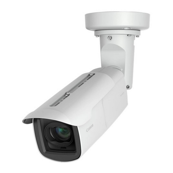
Network Camera
2
BIE-7248-000
ENGLISH
Installation Guide
This Installation Guide is comprised of pages [1/2] and [2/2]. Please be sure to read the
included "Safety Precautions" leaflet for correct use. After reading the Installation Guide,
keep it in a safe location.
There are two types of cameras: Hydrophilic Coating Model and Non-hydrophilic Coating Model.
The hydrophilic coating models have a "hydrophilic coating model label" attached on the
product's exterior cover.
Hydrophilic Coating Models
• VB-H761LVE (H2)/VB-H760VE (H2)/VB-H751LE (H2)/
VB-M741LE (H2)/VB-M740E (H2)/VB-H761LVE-H/
VB-H751LE-H/VB-M741LE-H
Non-hydrophilic Coating Models
• VB-H761LVE/VB-H760VE/VB-H751LE/VB-M741LE/VB-M740E
For handling the hydrophilic coating, be sure to read the
included "Safety Precautions".
Do not remove the protective sheet of the hydrophilic coating model until installation of
the camera is completed.
* Some cameras are not available in certain countries or regions.
Request a professional installer for all installation work. Never try to install
Caution
the camera yourself. Doing so may result in unforeseen accidents such as
dropping the camera or electric shock.
Symbols used in this Installation Guide
: VB-H761LVE (H2)/VB-H761LVE-H/VB-H761LVE
: VB-H760VE (H2)/VB-H760VE
: VB-M741LE (H2)/VB-M741LE-H/VB-M741LE
: Hydrophilic Coating Model
Items indicated in the Installation Guide [2/2] with this icon are not included with the
camera, and should be provided by the user.
Check Included Items
Camera, Screw (M4) x 4
Template
Installation Guide (This document)
Warranty Card
Safety Wire, Screw (M3) x 1
Dedicated Wrench
Waterproof Packing
GND Screw (M3) x 1
Zip Tie (for LAN Cable)
I/O Interface Cable (BK2-0035-000)
Power Interface Cable (BK2-0036-000)
Waterproofing Tape
Weather Shield WS700-VB Installation Guide (VB-H761LVE-H/VB-H751LE-H/VB-M741LE-H only)
Weather Shield, Screw (M3) x 2
Accessories
The following accessories can be purchased separately as necessary. Some accessories are
not available in certain countries or regions.
Conduit Box CB740-VB
Dedicated accessory used to protect wiring cables that cannot be stored above the ceiling.
This can be attached to the composite pipe.
Pendant Mounting Kit PC640-VB
Dedicated accessory used to install the camera to the end of pipe that extends from high
ceilings, such as in big-box stores.
Canon AC Adapter PA-V18
Dedicated AC adapter for this camera.
Notes for When and After Installing the Camera
When Installing the Camera
Installing the Camera Outdoors
•
Be sure to wrap with
waterproofing tape. Please refer to the "Wrapping the
Waterproofing Tape" cautions below for how to wrap.
• When mounting the camera onto a wall or other upright
surface, make sure that the cables and composite pipe
are placed below the camera to prevent rain infiltration.
• If connecting the camera to the composite pipe by wiring,
bridge the gap using the conduit box (sold separately).
When connecting the conduit box and the pipe, apply
silicon sealant to seal it tightly after attaching the pipe to
prevent water getting in as necessary.
Wrapping the Waterproofing Tape
Properly waterproof the connections, as shown in the Installation Guide [2/2], using the waterproofing
tape (included). If not properly waterproofed, it may result in water intrusion, thereby causing breakdown.
• To prevent cable connections from shorting out, wrap each individual connection with
insulating tape, and then wrap all of the cables with waterproofing tape. Please refer to the
Installation Guide [2/2] for details on how to wrap the waterproofing tape.
• The camera conforms to the dust-resistant/waterproof specification (IP66), however the
cable ends that connect to external devices are not. Cable connections should be wrapped
with waterproofing tape, if there are any chances that it may get wet.
• Accessories for installation are not dust-proof/waterproof. Wrap the cable connections with
the included waterproofing tape, even if they can fit within the optional unit, because there
could be a chance of the cables getting wet.
Attaching the Weather Shield
Depending on the angle of view and the installed position, the weather shield can partially
block the view. Please check the image from the camera, and adjust as necessary.
The contents of this guide are subject to change without any prior notice.
/
/
/
/
/
/
/
/
/
/
Hydrophilic Coating
Model label
: VB-H751LE (H2)/VB-H751LE-H/VB-H751LE
: VB-M740E (H2)/VB-M740E
Before Using This Camera
Ceiling Plate
Multi-Cable (BK2-0057-000)
LAN Cable Cap
After Installing the Camera
How to Adjust the Tilt (T)/Rotation (R)(Hereinafter "TR")
After the installation, if there is a need to re-adjust the TR while in the
/
installed location, it is necessary to loosen the wedge part first, while the
TR lock screw-b*
the wedge part, loosen the TR lock screw-a*
times counterclockwise, then insert the TORX*
with a hammer. There is a possibility that the camera will suddenly tilt if
/
the TR lock screw-b*
*
1
Refer to the "Part Names" section for the location of the TR lock screw-a/b.
*
2
TORX is the trademark of Acument Intellectual Properties, LLC.
When the temperature within the camera is low (heater activation)
When the camera is powered by a 24 V AC/ PoE+ power source, the heater unit can be used.
The heater unit will be activated automatically when the temperature within the camera is low.
The orange LED will be lit, until the camera has warmed up enough to start transferring video.
Once the temperature within the camera has reached the level where it can transfer the video
once again, the orange LED will turn off.
When there is condensation on the lens protector after being turned on
Condensation may occur on the inside of the lens protector, when the power is turned on for
the first time after installation, or after not being turned on for a long time. The condensation
protective sheet
will dissipate after the power has been left on a while (this may take more than a day at the
longest). Please use the camera after confirming that the image can be captured correctly.
Before Installing the Camera
When Using a Memory Card
Loosen the screws with the dedicated wrench, open the memory card cover, and place a
memory card in the memory card slot. Once the memory card is placed, close the memory
card cover and tighten the screws with the dedicated wrench.
(SD memory card, SDHC memory card, or SDXC memory card can be used)
Part Names
1
Safety Precautions
13
14
15
16
17
18
1. Lens protector / 2. Weather shield
4. LED (Blue)*
1
/ 5. GND screw hole / 6. Power connection terminal
7. I/O & Audio combination connector
9. External Device I/O Terminals
10. Audio input terminal (Black) (common LINE IN and MIC IN)
11. Audio output terminal (White) (LINE OUT)
13. Pan (P) lock screw / 14. Tilt (T)/Rotation (R) lock screw-a /
15. Tilt (T)/Rotation (R) lock screw-b / 16. Pan axis adjustment screw /
17. Tilt axis adjustment screw / 18. Rotation axis adjustment screw / 19. Memory card cover /
20. Reset switch*
*
1
On: when powered on, during reboot, during normal use / Off: when [Turn Off] is selected
(please refer to the "Operation Guide")
2
Please refer to the "Operation Guide" for the method to reset the camera.
*
(x 2) on the right and left remain tightened. To release
1
1
by turning roughly eight
2
driver, and lightly hit it
1
(x 2) on the right and left are first loosened.
2
6 9 10
1
3
4
19
/ 3. LED (Orange)
/ 8. LAN connector (RJ45,100Base-TX) /
/
/ 12. Notched cap
/ 21. Memory card slot / 22. Reboot switch / 23. LED (Blue)*
2
5
8
6 7
11
8
12
Serial_ _ _ _ _ _ _ _ _ _ _ _ _ _ _ _ _
MAC_ _ _ _ _ _ _ _ _ _ _ _ _ _ _ _ _ _
20
21 22
23
/
/
/
/
1
Advertisement

Related Manuals for Canon VB-H761LVE


Summary of Contents for Canon VB-H761LVE
- Page 1 Zip Tie (for LAN Cable) I/O Interface Cable (BK2-0035-000) Power Interface Cable (BK2-0036-000) Waterproofing Tape Weather Shield WS700-VB Installation Guide (VB-H761LVE-H/VB-H751LE-H/VB-M741LE-H only) 6 9 10 Weather Shield, Screw (M3) x 2 Accessories The following accessories can be purchased separately as necessary. Some accessories are not available in certain countries or regions.
-
Page 2: Power Connection
FG (frame ground) Output terminal: 3.5 mm ( 0.14 in.) mini jack (monaural) 2: BLUE (fat) 24 V AC/12 V DC non-polar Output level: Max. 1 Vp-p * Use a speaker with an amplifier. © CANON INC. 2019 Printed in Japan... - Page 3 M3 x 2 BIM-7152-000 親水コーティングモデルの保護シートは、 カメラの設置が完了す るまで取り外さないでください( )。 Do not remove the protective sheet of the hydrophilic coating model until installation of the camera is completed ( ). Entfernen Sie die Schutzabdeckung des Modells mit hydrophiler Beschichtung erst, wenn die Installation der Kamera abgeschlossen ist ( ).
- Page 4 รั บ การติ ด ตั ้ ง อย่ า งเหมาะสม ให ้ลองเขย่ า กล ้องเบาๆ และขั น สกรู ใ ห ้แน่ น อี ก ครั ้ ง 케이블의 연결 부위에 동봉된 방수 테이프를 감아 주십시오. 나사를 조인 후 흔들어 봤을 때 고정되지 않았을 경우, 기어가 제대로 맞물린 상태가 아닙니다. 카메라를 가볍게 흔든 후, 나사를 다시 조여 주십시오. 245 (9.65) 83.5 (3-9/32) 60.5 (2.38) 21.0 (0.83) 21.0 (0.83) 150 ( 5.91) 35 (1.38) 21.0 (0.83) 21.0 (0.83) 214 (8.43) 288 (11.34) 102 (4.02) mm (in./pulg./po) © CANON INC. 2019 Printed in Japan...