Cobra CR6 Series Installation And Operation Manual
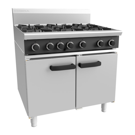
Static oven range
Hide thumbs
Also See for CR6 Series:
- Operation manual (24 pages) ,
- Installation and operation manual (25 pages)
Advertisement
Quick Links
Download this manual
See also:
Operating Manual
S t a t i c O v e n R a n g e
M o d e l s :
C R 6 ( 6 0 0 m m )
C R 9 ( 9 0 0 m m )
I N S T A L L A T I O N A N D O P E R A T I O N M A N U A L
242357-3
Advertisement

Related Manuals for Cobra CR6 Series


Summary of Contents for Cobra CR6 Series
- Page 1 S t a t i c O v e n R a n g e M o d e l s : C R 6 ( 6 0 0 m m ) C R 9 ( 9 0 0 m m ) I N S T A L L A T I O N A N D O P E R A T I O N M A N U A L 242357-3...
- Page 2 Moffat Limited Rolleston 7675 New Zealand AUSTRALIA Moffat Pty Limited E.Mail: vsales@moffat.com.au Main Office: (tel): +61 (03) 9518 3888 (fax): +61 (03 9518 3833 Service: (tel): 1800 622 216 Spares: (tel): 1800 337 963 Customer Service: (tel): 1800 335 315 (fax): 1800 350 281 CANADA Serve Canada...
- Page 3 Model Numbers Covered in this Specification General Gas Supply Requirements Gas Connection Dimensions Installation Requirements Unpacking Assembly Location Clearances Gas Connection Commissioning Operation Guide Description of Controls Open Burners Griddle Oven General After Each Use Daily Cleaning Weekly Cleaning Periodic Maintenance Open Burners Griddle Burners Oven...
- Page 4 We are confident that you will be delighted with your Cobra Series Ranges, and it will become a most valued appliance in your commercial kitchen. To ensure you receive the utmost benefit from your new Cobra Series Appliance, there are two important things you can do.
- Page 5 Model Covered in this Specification - CR6D[1] Range 4 Open Burners. CR6C[1] Range 2 Burners + 300mm Griddle. CR6B Range 600mm Griddle. CR9D[1] Range 6 Open Burners. CR9C[1] Range 4 Burners + 300mm Griddle. CR9B[1] Range 2 Burners + 600mm Griddle. CR9A Range 900mm Griddle.
- Page 6 Gas supply connection point is located at the rear of the appliance, approximately 130mm from the right hand side, 19mm from the rear and 656mm from the floor and is reached from beneath the appliance. (Refer to the ‘Dimensions’ below). For all Appliance Options, gas connection is ”...
- Page 7 Gas supply connection point is located at the rear of the appliance, approximately 130mm from the right hand side, 19mm from the rear and 656mm from the floor and is reached from beneath the appliance. (Refer to the ‘Dimensions’ below). For all Appliance Options, gas connection is ”...
- Page 8 Cobra Series Ranges are designed to provide years 1. Remove all loose components from the top of of satisfactory service and correct installation is the cooktop range and from inside the oven.
- Page 9 QUALIFIED SERVICE PERSON. of combustion products. 2. Installation must allow for a sufficient flow of 1. Cobra Series Oven Ranges do not require an fresh air for the combustion air supply. electrical connection, they function totally on the gas supply only.
- Page 10 NOTE: A Manual Isolation Valve must be fitted to the The following commissioning checks must be individual appliance supply line. carried out before the Range is handed over for use, to ensure that the unit operates correctly and the 4. Correctly locate the appliance into its final operator(s) understand correct...
- Page 11 Oven Main Burner Thermostat. Turning the Oven to ‘Stand-By’ Mode. Oven ‘Shut Down’. 1. Cobra appliances have been designed to provide simplicity of operation and 100% safety protection. Gas Control Knobs Griddle. (CR9-Gas Range 900mm Option shown)
- Page 12 NOTE: Only cooking pans from size Ø 150mm to Ø 420mm are suitable fo use on these open burners. Lighting the Open Burners (Standard / Flame Failure Options) a. Select the burner required, depress and turn the These griddles are fitted with Pilot and Flame Failure corresponding gas control knob anti-clockwise Protection as a standard option, which is to the ‘HIGH’...
- Page 13 5. The following chart indicates approximate oven centre temperatures that will be maintained at the knob markings. EAT EXPOSURE DANGER EXISTS WHEN OPENING THE OVEN HOT. DOOR WHILE THE OVEN IS STILL Gas Mark Temperature Conversions - Pilot Burner Ignition NOTE: This oven is fitted with a pilot as standard option and Approximate guide information only.
- Page 14 2. Always ensure that scraper tool blades are changed regularly to ensure that the scraper tool works efficiently and prevents damage to the griddle plate surface. 3. Clean the range castings with a stiff nylon brush or a flexible spatula to remove any food debris. 1.
- Page 15 a. Clean the Range cooking area using a soft cloth a. Remove the trivets from the top of the moistened with a mild detergent and hot water appliance, taking note that the trivets are manufactured with a lip on one edge, the lip solution.
- Page 16 a. Refit the trivet supports to the Range top, NOTE: ensuring that the trivet supports are correctly All maintenance operations should only be carried fitted. out by a qualified service person. NOTE: To achieve the best results cleaning must be regular ...
- Page 17 This section provides an easy reference guide to the more common problems that may occur during operation of your equipment. This fault finding guide is intended to help you accurately diagnose and correct problems with your equipment. Although this section covers the most common problems reported, you may encounter a problem not covered in this section.
- Page 18 Griddle Burners Fault Possible Cause Remedy Pilot won’t light Gas control knob not being held in Hold in button while lighting pilot. for long enough. No gas supply. Ensure gas is connected and turned on (bottles not empty). Gas pressure too low. Call service provider.
- Page 19 Oven Fault Possible Cause Remedy Piezo ignitor not sparking. Short in high tension lead. Call service provider. Piezo ignitor faulty. Call service provider. Piezo electrode cracked or sooted Call service provider. Pilot won’t light. Knob on gas control valve won’t Remove obstruction.
- Page 20 Oven (Cont’d) Fault Possible Cause Remedy Set temperature not reached Gas supply fluctuating. Check supply for correct pressure. Gas valve not set up correctly. Call service provider. Thermostat out of calibration. Call service provider. Gas control faulty. Call service provider. Oven too hot Gas valve not set up correctly.
- Page 21 Flame Failure Valve Shown 4. Unscrew and remove injectors (½" A/F) from the gas valves. 5. Determine correct injector sizes for the corresponding gas from the rating plate attached to NOTE: Injector the underside of the These conversions should only be carried out by right hand side, front Cooktop lower trim.
- Page 22 Griddle Pilot Burner Griddle Main Burner a. Disconnect the pilot supply tube from the pilot burner. a. With the gas supply turned off at the main supply, remove the griddle plate section by b. Remove the existing pilot injector and replace with the correct size for the gas being used.
- Page 23 Low Fire Adjustment Main Burner Low Fire Screw 1. Turn off gas supply at main supply. 2. Remove oven racks, oven tray and flame baffle from inside oven. 3. Remove the oven main burner. 1. To change the thermostat ‘Low Fire’ screw for the gas type required, remove the following:- ...
- Page 24 On completion of gas conversion, replace gas type identification label located at:- - Rear of appliance, above gas connection. - Beside the rating plate. Before leaving the converted installation; 1. Check all gas connections for leakages using soapy water or other gas detecting equipment. O NOT USE A NAKED FLAME TO CHECK FOR GAS LEAKAGES 2.
- Page 25 Category: (20, 37) 2H3P. Flue Type: Burner Injector Ø 1.90mm Ø 1.20mm Open Burner Low Fire Setting ¾ turn open c.c.w. ¼ turn open c.c.w. Burner Aeration Setting 16mm open 16mm open Burner Injector Ø 2.00mm Ø 1.25mm Low Fire Setting turn open c.c.w.
-
Page 26: Replacement Parts List
Replacement Parts List IMPORTANT: Only genuine qualified replacement parts should be used for the servicing and repair of this appliance. The instructions supplied with the parts should be followed when replacing components. For further information and servicing instructions, contact your nearest qualified service branch (contact details are as shown on the reverse of the front cover of this manual). -
Page 27: Gas Regulator
Oven 022446 Oven Burner (CR6). 230441 Oven Burner (CR9). 228703 Eurosit Gas Control Kit. 018682 Thermocouple (1500mm Long). 230586 Piezo Igniter. 232691 HT Lead 1600mm. 242440 Oven Rack (CR6). 242428 Oven Rack (CR9). 230462 Oven Tray. 011005 Ball Catch Assy. 230487 Top Striker Plate.
Need help?
Do you have a question about the CR6 Series and is the answer not in the manual?
Questions and answers