Juniper MX960 Hardware Manual
Universal routing platform
Hide thumbs
Also See for MX960:
- Hardware manual (596 pages) ,
- Quick start manual (34 pages) ,
- Installation instructions manual (16 pages)
Table of Contents
Advertisement
Quick Links
Advertisement
Table of Contents
Troubleshooting

Related Manuals for Juniper MX960


Summary of Contents for Juniper MX960
- Page 1 MX960 Universal Routing Platform Hardware Guide Published 2019-12-03...
- Page 2 END USER LICENSE AGREEMENT The Juniper Networks product that is the subject of this technical documentation consists of (or is intended for use with) Juniper Networks software. Use of such software is subject to the terms and conditions of the End User License Agreement (“EULA”) posted at https://support.juniper.net/support/eula/.
-
Page 3: Table Of Contents
MX960 Host Subsystem LEDs on the Craft Interface | 20 MX960 Power Supply LEDs on the Craft Interface | 20 MX960 DPC and MPC LEDs on the Craft Interface | 20 MX960 FPC LEDs on the Craft Interface | 21... - Page 4 MX960 Cable Manager Description | 22 Cooling System Components and Descriptions | 25 MX960 Cooling System Description | 25 MX960 Fan LED | 27 Host Subsystem Components and Descriptions | 29 MX960 Host Subsystem Description | 29 MX960 Host Subsystem LEDs | 30...
- Page 5 MX960 Application Services Modular Line Card Description | 83 MX960 AS MLC Function | 83 AS MLC Components | 84 MX960 SCB, Power Supply, and Cooling System Requirements for AS MLC | 85 MX960 Application Services Modular Storage Card Description | 86...
- Page 6 MPCs Supported by MX Series Routers | 116 Services Processing Card—MX-SPC3 | 123 Services Processing Card—MX-SPC3 Services Card | 123 MX-SPC3 Services Card Overview and Support on MX240, MX480, and MX960 Routers | 123 MX-SPC3 Services Card | 124 Power System Components and Descriptions | 129...
- Page 7 Rack Size and Strength | 184 Spacing of Mounting Bracket Holes | 185 Connection to the Building Structure | 185 Clearance Requirements for Airflow and Hardware Maintenance for the MX960 Router | 185 MX960 Cabinet Size and Clearance Requirements | 187...
- Page 8 Power Requirements for an MX960 Router | 205 Calculating Power Requirements for MX960 Routers | 215 AC Power Circuit Breaker Requirements for the MX960 Router | 220 AC Power Cord Specifications for the MX960 Router | 221 DC Power Requirements, Specifications, and Guidelines | 225...
- Page 9 Installing the MX960 Router | 263 Installing an MX960 Router Overview | 263 Removing Components from the MX960 Router Chassis Before Installing It with a Lift | 265 Removing the Power Supplies Before Installing an MX960 Router with a Lift | 265...
- Page 10 Reinstalling the DPCs After Installing the MX960 Router with a Lift | 327 Reinstalling the FPCs After Installing the MX960 Router with a Lift | 329 Reinstalling the Standard Cable Manager After Installing an MX960 Router with a Lift | 330 Connecting the MX960 Router to Power | 333...
- Page 11 Connecting the MX960 Router to Management and Alarm Devices | 358 Connecting the MX960 Router to a Network for Out-of-Band Management | 358 Connecting the MX960 Router to a Management Console or Auxiliary Device | 359 Connecting an MX960 Router to an External Alarm-Reporting Device | 360...
- Page 12 Installing an MX960 AS MSC | 422 Installing an MX960 AS MXC | 423 Installing an SFP or XFP Transceiver into an MX960 DPC, MPC, MIC, or PIC | 425 Replacing a CFP2 Transceiver | 426 Removing a CFP2 Transceiver | 427...
- Page 13 Replacing Connections to MX960 Routing Engine Interface Ports | 473 Replacing the Management Ethernet Cable on an MX Series Router | 473 Replacing the Console or Auxiliary Cable on an MX960 Router | 474 Upgrading to the RE-S-X6-64G Routing Engine in a Redundant Host Subsystem | 475...
- Page 14 Installing a Cable on an MX960 DPC, MPC, MIC, or PIC | 524 Replacing an SFP or XFP Transceiver on an MX960 DPC, MPC, MIC, or PIC | 526 Removing an SFP or XFP Transceiver from an MX960 DPC, MPC, MIC, or PIC | 527...
- Page 15 Power On the MX960 Router | 581 Complete the SCBE2-MX Upgrade | 582 Upgrading an MX240, MX480, or MX960 Router to Use the SCBE3-MX | 583 Upgrade the Routing Engine | 584 Install the Routing Engine into the SCBE3-MX | 584...
- Page 16 Maintaining MX960 MICs | 612 Maintaining MX960 MPCs | 613 Maintaining MX960 PICs | 616 Maintaining Cables That Connect to MX960 DPCs, MPCs, MICs, or PICs | 617 Maintaining MX-SPC3 Services Card | 619 Maintaining MX-SPC3 Services Card | 620...
- Page 17 Contacting Customer Support | 675 Contacting Customer Support | 675 Locating Component Serial Numbers | 677 Displaying MX960 Router Components and Serial Numbers | 677 MX960 Routing Engine Serial Number Label | 680 MX960 Chassis Serial Number Label | 681...
- Page 18 xviii Qualified Personnel Warning | 705 Fire Safety Requirements | 706 Fire Suppression | 706 Fire Suppression Equipment | 706 Warning Statement for Norway and Sweden | 707 Installation and Maintenance Safety Guidelines and Warnings | 709 Installation Instructions Warning | 710 Chassis and Component Lifting Guidelines | 710 Ramp Warning | 711 Rack-Mounting and Cabinet-Mounting Warnings | 711...
- Page 19 Agency Approvals and Compliance Statements | 751 Agency Approvals for MX960 Routers | 751 Compliance Statements for NEBS for the MX960 Router | 752 Compliance Statements for EMC Requirements for the MX960 Router | 753 Canada | 753 European Community | 753...
-
Page 20: About The Documentation
Use this guide to install hardware and perform initial software configuration, routine maintenance, and troubleshooting for the MX960 5G Universal Routing Platform. After completing the installation and basic configuration procedures covered in this guide, refer to the Junos OS documentation for information about further software configuration. -
Page 21: Merging A Full Example
xxii If the example configuration contains the top level of the hierarchy (or multiple hierarchies), the example is a full example. In this case, use the load merge command. If the example configuration does not start at the top level of the hierarchy, the example is a snippet. In this case, use the load merge relative command. -
Page 22: Merging A Snippet
xxiii Merging a Snippet To merge a snippet, follow these steps: 1. From the HTML or PDF version of the manual, copy a configuration snippet into a text file, save the file with a name, and copy the file to a directory on your routing platform. For example, copy the following snippet to a file and name the file ex-script-snippet.conf. - Page 23 xxiv Table 1: Notice Icons Icon Meaning Description Informational note Indicates important features or instructions. Caution Indicates a situation that might result in loss of data or hardware damage. Warning Alerts you to the risk of personal injury or death. Laser warning Alerts you to the risk of personal injury from a laser.
- Page 24 Table 2: Text and Syntax Conventions (continued) Convention Description Examples Italic text like this Represents variables (options for Configure the machine’s domain which you substitute a value) in name: commands or configuration [edit] statements. root@# set system domain-name domain-name Text like this Represents names of configuration To configure a stub area, include statements, commands, files, and...
-
Page 25: Documentation Feedback
URL or page number, and software version (if applicable). Requesting Technical Support Technical product support is available through the Juniper Networks Technical Assistance Center (JTAC). If you are a customer with an active Juniper Care or Partner Support Services support contract, or are... -
Page 26: Self-Help Online Tools And Resources
JTAC hours of operation—The JTAC centers have resources available 24 hours a day, 7 days a week, 365 days a year. Self-Help Online Tools and Resources For quick and easy problem resolution, Juniper Networks has designed an online self-service portal called the Customer Support Center (CSC) that provides you with the following features: Find CSC offerings: https://www.juniper.net/customers/support/... -
Page 27: Overview
PART Overview System Overview | 3 Chassis Components and Descriptions | 7 Cooling System Components and Descriptions | 25 Host Subsystem Components and Descriptions | 29 Line Card Components and Descriptions | 63 Services Processing Card—MX-SPC3 | 123 Power System Components and Descriptions | 129 Switch Control Board Components and Descriptions | 145... -
Page 29: System Overview
Routing Engines, and Switch Control Boards. The MX960 router is 16 rack units (U) tall. Three routers can be stacked in a single floor-to-ceiling rack, for increased port density per unit of floor space. The router provides 14 slots that can be populated with 11 or 12 Dense Port Concentrators (DPCs) or Modular Port Concentrators (MPCs), six Flexible PIC Concentrators (FPCs), and two Switch Control Boards (SCBs) in nonredundant fabric configurations. - Page 30 (PFE). Each PFE enables a throughput of 10 Gbps. Up to two PICs can be installed in each FPC. Fully populated, the MX960 supports up to 12 PICs. Up to two Modular Interface Cards (MICs) can be installed in each MPC. Fully populated, the MX960 supports up to 24 MICs.
- Page 31 MPC. All board-to-board information is passed over Ethernet except for low-level status and commands. Management signals—Provide low-level status diagnostic support. RELATED DOCUMENTATION MX960 Component Redundancy | 12 MX960 Router Physical Specifications | 177 MX960 Chassis Description | 7 MX960 Host Subsystem Description | 29 MX960 Craft Interface Overview | 17...
-
Page 32: Chassis Components And Descriptions
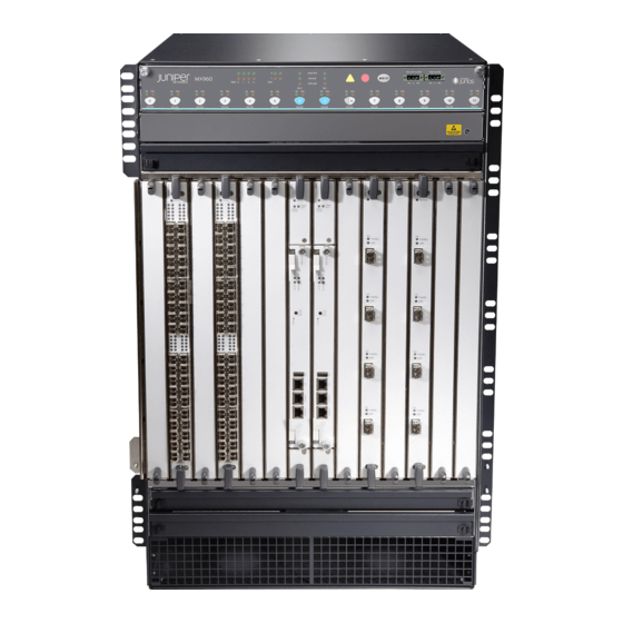
MX960 Rack-Mounting Hardware | 16 MX960 Craft Interface Overview | 17 MX960 Alarm Relay Contacts on the Craft Interface | 18 MX960 Alarm LEDs and Alarm Cutoff/Lamp Test Button | 18 MX960 Component LEDs on the Craft Interface | 19... - Page 33 48-U rack if the rack can handle their combined weight, which can be greater than 748 lb (339.28 kg). Mounting hardware includes front-mounting flanges on the front of the chassis, and two center-mounting brackets attached to the center of the chassis. Figure 1: Front View of a Fully Configured MX960 Router Chassis...
- Page 34 Figure 2: Rear View of a Fully Configured AC-Powered MX960 Router Chassis Air exhaust Input mode switch AC Power supplies Power supply ejectors Grounding points ESD point Figure 3: Rear View of a Fully Configured DC-Powered MX960 Router Chassis Air exhaust...
- Page 35 Figure 4: Rear View of a Fully Configured AC-powered High-Capacity Second-Generation MX960 Router Chassis Air exhaust Power supply ejectors — — Power distribution unit cover Grounding points — — High-capacity second-generation AC power supplies ESD point — —...
- Page 36 Figure 5: Rear View of a Fully Configured MX960 Router Chassis with Universal High-Voltage Second-Generation Power Supplies Air exhaust Power supply ejectors — — Power distribution unit cover Grounding points — — High-capacity second-generation AC power supplies ESD point —...
-
Page 37: Mx960 Component Redundancy
RELATED DOCUMENTATION MX960 Router Overview | 3 Displaying MX960 Router Components and Serial Numbers | 677 Guidelines for Packing Hardware Components for Shipment | 696 Returning a Hardware Component to Juniper Networks, Inc. | 698... - Page 38 Table 5: MX960 Router Hardware Components and CLI Terminology Component Hardware Model Number CLI Name Description Chassis MX960BASE-AC MX960 “MX960 Router Physical Specifications” on page 177 MX960BASE-DC “MX960 Chassis Description” on page 7 Craft Interface Panel CRAFT-MX960-S Front Panel Display “MX960 Craft Interface...
- Page 39 Table 5: MX960 Router Hardware Components and CLI Terminology (continued) Component Hardware Model Number CLI Name Description “MICs Supported by MX Series Routers” on page 99 “MX960 Modular Interface Card in the MX Series Interface Module Reference. Description” on page 98...
-
Page 40: Mx960 Midplane Description
Table 5: MX960 Router Hardware Components and CLI Terminology (continued) Component Hardware Model Number CLI Name Description Power supply blank PWR-BLANK-MX960 “MX960 Power System panel Overview” on page 129 RELATED DOCUMENTATION MX960 Router Overview | 3 MX960 DPC Port and Interface Numbering | 69... -
Page 41: Mx960 Rack-Mounting Hardware
MX960 Power System Overview | 129 MX960 Rack-Mounting Hardware The rack-mounting hardware for the MX960 router includes: The large mounting shelf for mounting in four-post racks, cabinets, and open-frame racks The small mounting shelf for front-mounting in a four-post rack or cabinet... -
Page 42: Mx960 Craft Interface Overview
MX960 Chassis Description | 7 MX960 Midplane Description | 15 Installing the MX960 Mounting Hardware for Center-Mounting in an Open-Frame Rack | 260 Installing the MX960 Mounting Hardware for Front-Mounting in an Open-Frame Rack | 257 Installing the MX960 Mounting Hardware for a Four-Post Rack or Cabinet | 255... -
Page 43: Mx960 Alarm Relay Contacts On The Craft Interface
Figure 8: Alarm Relay Contacts RELATED DOCUMENTATION Disconnecting the Alarm Relay Wires from the MX960 Craft Interface | 433 Connecting the Alarm Relay Wires to the MX960 Craft Interface | 367 MX960 Alarm LEDs and Alarm Cutoff/Lamp Test Button Two large alarm LEDs are located at the upper right of the craft interface. -
Page 44: Mx960 Component Leds On The Craft Interface
MX960 Host Subsystem LEDs on the Craft Interface | 20 MX960 Power Supply LEDs on the Craft Interface | 20 MX960 DPC and MPC LEDs on the Craft Interface | 20 MX960 FPC LEDs on the Craft Interface | 21... -
Page 45: Mx960 Host Subsystem Leds On The Craft Interface
Power supply has failed or power input has failed. steadily MX960 DPC and MPC LEDs on the Craft Interface Each DPC or MPC has LEDs on the craft interface that indicate its status. The LEDs, labeled 0 through 5, 2/6, and 7 through 11, are located along the bottom of the craft interface. Slot 2/6 is for an additional DPC, FPC, MPC, or SCB. -
Page 46: Mx960 Fpc Leds On The Craft Interface
Card has failed. steadily MX960 FPC LEDs on the Craft Interface An FPC takes up two DPC slots when installed in an MX Series router. The LEDs, labeled 0 through 5, 2/6, and 7 through 11, are located along the bottom of the craft interface. Slot 2/6 is for an additional DPC, FPC, MPC, or SCB. -
Page 47: Mx960 Fan Leds On The Craft Interface
Fan has failed. steadily RELATED DOCUMENTATION MX960 Craft Interface Overview | 17 MX960 Alarm Relay Contacts on the Craft Interface | 18 MX960 Cable Manager Description The standard cable manager (see Figure 9 on page 23) is a tray located below the line-card cage, which has a row of fourteen dividers for securing the cables for each Dense Port Concentrator (DPC), Modular Port Concentrator (MPC), Modular Interface Card (MIC), or PIC. - Page 48 You can use cable strips or other ties to gently secure the cables in the standard cable manager. To secure the cables in place, loop the tie through the cable anchor and secure the tie. You can pull the standard cable manager up and outward to lock it into the maintenance position.
- Page 49 Figure 11: Extended Cable Manager Cover RELATED DOCUMENTATION Replacing the MX960 Cable Manager | 437 Verifying the Version of the MX960 Cable Manager | 626...
-
Page 50: Cooling System Components And Descriptions
The fan trays are hot-insertable and hot-removable. The MX960 requires high-capacity fan trays to satisfy cooling requirements for high-density DPCs and MPCs. When replacing normal-capacity fan trays with high-capacity fan trays, you must replace them in both the upper and lower fan trays. - Page 51 Figure 12: Airflow Through the Chassis The host subsystem monitors the temperature of the router components. When the router is operating normally, the fans function at lower than full speed. If a fan fails or the ambient temperature rises above a threshold, the speed of the remaining fans is automatically adjusted to keep the temperature within the acceptable range.
-
Page 52: Mx960 Fan Led
Maintaining the MX960 Fan Trays | 592 MX960 Fan LED Each fan has an LED that displays its status. The fan LEDs are located on the top left of the craft interface. For more information, see “MX960 Fan LEDs on the Craft Interface” on page... - Page 53 RELATED DOCUMENTATION MX960 Cooling System Description | 25 Maintaining the MX960 Fan Trays | 592 Troubleshooting the MX960 Cooling System | 656...
-
Page 54: Host Subsystem Components And Descriptions
RELATED DOCUMENTATION MX960 Host Subsystem LEDs | 30 Maintaining the MX960 Host Subsystem | 595 Taking an MX960 Host Subsystem Offline Effect of Taking the MX960 Host Subsystem Offline Replacing an MX960 Routing Engine | 461... -
Page 55: Mx960 Host Subsystem Leds
Routing Engine is hot-pluggable. A Routing Engine that is not redundant is hot-pluggable. Supported Routing Engines The MX960 router supports the following Routing Engines: RE-S-1300-2048 supported for Junos OS Release 8.2 and later. RE-S-2000-4096 supported for Junos OS Release 8.2 and later. -
Page 56: Routing Engine Function
On the MX960 router, a Routing Engine installed in SCB slot 2/6 receives no power and supplies no additional routing functions. If no SCB is installed in slot 2/6, install a blank panel in the slot. -
Page 57: Mx Routing Engine Leds
RJ-45 Connector Pinouts for MX Series Routing Engine AUX and CONSOLE Ports | 201 RJ-45 Connector Pinouts for an MX Series Routing Engine ETHERNET Port | 200 Replacing an MX960 Routing Engine | 461 MX Routing Engine LEDs Each Routing Engine has four LEDs that indicate its status. The LEDs, labeled MASTER, HDD, ONLINE, and FAIL, are located directly on the faceplate of the Routing Engine. -
Page 58: Routing Engine Specifications
Replacing an MX960 Routing Engine | 461 Routing Engine Specifications Table 14 on page 33 lists the current specifications for Routing Engines supported on M Series, MX Series, and T Series routers. Table 15 on page 38 lists the hardware specifications of the Routing Engines with VMHost support. - Page 59 Table 14: Routing Engine Specifications (continued) First Switch Connection Junos OS Control Routing Engine Processor Memory to PFEs Disk Media Support Board RE-S-2000-4096 2.0-GHz 4096 MB Gigabit 40 GB 1 GB SCB, SCBE Pentium Ethernet hard CompactFlash disk card...
- Page 60 Table 14: Routing Engine Specifications (continued) First Switch Connection Junos OS Control Routing Engine Processor Memory to PFEs Disk Media Support Board RE-C1800 1.8-GHz 8 GB Gigabit 4 GB T1600 CB-T for a Ethernet CompactFlash router in a standalone card routing router.
- Page 61 Table 14: Routing Engine Specifications (continued) First Switch Connection Junos OS Control Routing Engine Processor Memory to PFEs Disk Media Support Board RE-C2600 2.6-GHz 16 GB Gigabit 4 GB TX Matrix – Ethernet CompactFlash Plus router: card 9.6R2 RE-A-1800x2 1800-MHz 8 GB or Gigabit 32 GB...
- Page 62 Table 14: Routing Engine Specifications (continued) First Switch Connection Junos OS Control Routing Engine Processor Memory to PFEs Disk Media Support Board RE-S-X6-64G, 2 Ghz 64 GB Gigabit 15.1F4, SCBE2, RE-S-X6-64G-LT Ethernet 50-GB 16.1 SCBE3 SSDs REMX2K-X8-64G 2.3 Ghz 64 GB Gigabit 15.1F5-S1, –...
- Page 63 Table 15: Hardware Specifications of the RE-MX-X6, RE-MX-X8, RE-PTX-X8, RCBPTX, RE-QFX10002-60C, and RE-PTX10002-60C Routing Engines Model Number Supported on Device Specifications RE-S-X6-64G MX240, MX480, and 6-core Haswell CPU MX960 Wellsburg PCH-based Routing Engine with 64-GB DRAM and two 64-GB solid-state drives (SSDs)
- Page 64 Table 15: Hardware Specifications of the RE-MX-X6, RE-MX-X8, RE-PTX-X8, RCBPTX, RE-QFX10002-60C, and RE-PTX10002-60C Routing Engines (continued) Model Number Supported on Device Specifications REMX2K-X8-64G MX2020 and MX2010 8-core Haswell CPU Wellsburg PCH-based Routing Engine with 64-GB DRAM and two 64-GB SSDs RE-PTX-X8-64G PTX5000 8-core Haswell CPU...
- Page 65 Table 16: End-of-Life Routing Engine Specifications Routing Connection First Junos Engine Processor Memory to PFEs Disk Media OS Support EOL Details RE-333-256 333-MHz 256 MB Fast 6.4 GB 80 MB PSN-2003-01-063 Pentium II Ethernet hard disk CompactFlash card RE-333-768 333-MHz 768 MB Fast 6.4 GB...
-
Page 66: Supported Routing Engines By Router
MX104 Routing Engines | 45 MX204 Routing Engine | 46 MX240 Routing Engines | 46 MX480 Routing Engines | 47 MX960 Routing Engines | 49 MX2008 Routing Engines | 50 MX2010 Routing Engines | 50 MX2020 Supported Routing Engines | 51... -
Page 67: M7I Routing Engines
T4000 Routing Engines | 58 TX Matrix Routing Engines | 59 TX Matrix Plus Routing Engines | 60 TX Matrix Plus (with 3D SIBs) Routing Engines | 60 The following tables list the Routing Engines that each router supports, the first supported release for the Routing Engine in the specified router, the management Ethernet interface, and the internal Ethernet interfaces for each Routing Engine. -
Page 68: M40E Routing Engines
Table 18: M10i Routing Engines First Supported Management Name in CLI 32-bit Junos OS Ethernet Internal Ethernet Model Number Output Release Interface Interface RE-400-768 (EOL details: RE-5.0 fxp0 fxp1 TSB16445) fxp2 RE-850-1536 (EOL details: RE-850 fxp0 fxp1 TSB15553) fxp2 RE-B-1800X1-4G RE-B-1800x1 11.4R4 fxp0... -
Page 69: M320 Routing Engines
Table 20: M120 Routing Engines First First Supported Supported Management Internal Name in CLI 32-bit Junos OS 64-bit Junos Ethernet Ethernet Model Number Output Release OS Release Interface Interface RE-A-1000-2048 RE-A-1000 8.0R2 – fxp0 fxp1 fxp2 RE-A-2000-4096 RE-A-2000 8.0R2 – fxp0 bcm0 RE-A-1800X2-8G... -
Page 70: Mx5, Mx10, Mx40, And Mx80 Routing Engine
Table 21: M320 Routing Engines (continued) First First Supported Supported Management Internal Name in CLI 32-bit Junos OS 64-bit Junos Ethernet Ethernet Model Number Output Release OS Release Interface Interface RE-A-1800X2-8G RE-A-1800x2 11.4R5 10.4 fxp0 12.1R3 bcm0 RE-A-1800X2-16G RE-A-1800x2 11.4R5 10.4 fxp0 12.1R3... -
Page 71: Mx204 Routing Engine
Table 23: MX104 Routing Engines First Supported First Supported Management Internal Model Name in CLI 32-bit Junos OS 64-bit Junos OS Ethernet Ethernet Number Output Release Release Interface Interface RE-S-MX104 Routing Engine 13.2 – fxp0 fxp1 fxp2 MX204 Routing Engine Table 24 on page 46 lists the Routing Engines supported by the MX204 router. -
Page 72: Mx480 Routing Engines
Table 25: MX240 Supported Routing Engines (continued) First Supported First Supported Management Internal Name in CLI 32-bit Junos 64-bit Junos Ethernet Ethernet Model Number Output OS Release OS Release Interface Interface RE-S-1800X2-8G RE-S-1800x2 11.4R5 10.4 fxp0 (EOL details: 12.1R3 TSB16556 RE-S-1800x2-16G RE-S-1800x2 11.4R5... - Page 73 Table 26: MX480 Supported Routing Engines First Supported First Supported Management Internal Name in CLI 32-bit Junos 64-bit Junos Ethernet Ethernet Model Number Output OS Release OS Release Interface Interface RE-S-1300-2048 RE-S-1300 – fxp0 fxp1 (EOL details: fxp2 TSB16556 RE-S-2000-4096 RE-S-2000 –...
-
Page 74: Mx960 Routing Engines
MX960 Routing Engines Table 27 on page 49 lists the Routing Engines supported by MX960 routers. Table 27: MX960 Supported Routing Engines First First Supported Supported Management Internal Name in CLI 32-bit Junos 64-bit Junos Ethernet Ethernet Model Number Output... -
Page 75: Mx2008 Routing Engines
Table 27: MX960 Supported Routing Engines (continued) First First Supported Supported Management Internal Name in CLI 32-bit Junos 64-bit Junos Ethernet Ethernet Model Number Output OS Release OS Release Interface Interface RE-S-X6-128G RE-S-2X00x6-128 – 18.1R1 fxp0 ixlv0, igb0 MX2008 Routing Engines Table 28 on page 50 lists the Routing Engines supported by MX2008 routers. -
Page 76: Mx2020 Supported Routing Engines
Table 29: MX2010 Supported Routing Engines (continued) Management Internal Name in CLI First Supported 64-bit Ethernet Ethernet Model Number Output Junos OS Release Interface Interface REMX2K-1800-32G-S RE-S-1800x4 12.3R4 fxp0 13.2R1 REMX2K-X8-64G RE-S-2X00x8 15.1F5-S1 fxp0 ixlv0 16.1R2 ixlv1 16.2R1 REMX2K-X8-64G-LT RE-S-2X00x8 17.2R1 fxp0 ixlv0... -
Page 77: Mx10003 Routing Engines
Table 30: MX2020 Supported Routing Engines (continued) Management Internal Name in CLI First Supported 64-bit Ethernet Ethernet Model Number Output Junos OS Release Interface Interface REMX2K-X8-64G-LT RE-S-2X00x8 17.2R1 fxp0 ixlv0 ixlv1 REMX2K-X8-128G RE-MX200X8-128G 18.1R1 fxp0 ixlv0 ixlv1 MX10003 Routing Engines Table 31 on page 52 lists the Routing Engines supported by MX10003 routers. -
Page 78: Ptx1000 Routing Engines
Table 32: MX10008 Routing Engines Name in CLI First Supported Management Internal Ethernet Model Number Output Junos OS Release Ethernet Interface Interface JNP10K-RE1 RE X10 18.2R1 bme0 bme1 PTX1000 Routing Engines Table 33 on page 53 lists the Routing Engine supported on the PTX1000. NOTE: The PTX1000 supports 64-bit Junos OS only. -
Page 79: Ptx5000 Routing Engines
Table 34: PTX3000 Routing Engines (continued) Management Name in CLI First Supported Junos OS Ethernet Internal Ethernet Model Number Output Release Interface Interface RCB-PTX-X6-32G RE-PTX-2X00x6 16.1R4 ixlv0 17.1R1 ixlv1 This Routing Engine does not support Junos OS Release 16.2. PTX5000 Routing Engines Table 35 on page 54 lists the Routing Engines supported on the PTX5000. -
Page 80: Ptx10008 And Ptx10016 Routing Engines
Table 35: PTX5000 Routing Engines (continued) Management Internal First Supported Junos Ethernet Ethernet Model Number Name in CLI Output OS Release Interface Interface RE-PTX-X8-64G RE-PTX-2X00x8 15.1F4 ixlv0 16.1R1 ixlv1 RE-PTX-X8-128G RE-PTX-2X00x8-128G 18.1R1 ixlv0 ixlv1 PTX10008 and PTX10016 Routing Engines Table 36 on page 55 lists the Routing Engines supported on the PTX10008 and PTX10016 routers. -
Page 81: T640 Routing Engines
Table 37: T320 Routing Engines First Supported Management Name in CLI 32-bit Junos OS Ethernet Internal Ethernet Model Number Output Release Interface Interface RE-600-2048 (EOL details: RE-3.0 or RE-3.0 fxp0 fxp1 TSB14373) (RE-600) fxp2 RE-1600-2048 (EOL details: RE-4.0 fxp0 fxp1 TSB14374 fxp2 RE-A-2000-4096... -
Page 82: T1600 Routing Engines
Table 38: T640 Routing Engines (continued) First Supported First Supported Management Internal Name in CLI 32-bit Junos OS 64-bit Junos OS Ethernet Ethernet Model Number Output Release Release Interface Interface RE-DUO-C1800-8G RE-DUO-1800 32-bit Junos OS on 64-bit Junos OS on bcm0 a standalone T640 a standalone T640... -
Page 83: T4000 Routing Engines
Table 39: T1600 Routing Engines (continued) First Supported First Supported Management Internal Name in CLI 32-bit Junos OS 64-bit Junos OS Ethernet Ethernet Model Number Output Release Release Interface Interface RE-1600-2048 (EOL RE-4.0 – fxp0 fxp1 details: TSB14374 (RE-1600) fxp2 RE-A-2000-4096 RE-A-2000 –... -
Page 84: Tx Matrix Routing Engines
NOTE: The T4000 router supports 64-bit Junos OS only. Table 40: T4000 Routing Engines Management Internal Name in CLI First Supported 64-bit Junos Ethernet Ethernet Model Number Output OS Release Interface Interface RE-DUO-C1800-8G RE-DUO-1800 Standalone T4000 router: 12.1 bcm0 T4000 router in a routing matrix: 13.1 RE-DUO-C1800-16G RE-DUO-1800... -
Page 85: Tx Matrix Plus Routing Engines
Table 41: TX Matrix Routing Engines (continued) First First Supported Supported Management Internal Name in CLI 32-bit Junos 64-bit Junos Ethernet Ethernet Model Number Output OS Release OS Release Interface Interface RE-DUO-C1800-8G RE-DUO-1800 11.4R9 11.4R9 bcm0 RE-DUO-C1800-16G RE-DUO-1800 11.4R9 11.4R9 bcm0 The TXP router supports two control boards, CB-TX and CB-LCC. - Page 86 Table 43: Routing Engines on TX Matrix Plus with 3D SIBs First Supported First Supported Management Internal Name in CLI 32-bit Junos 64-bit Junos OS Ethernet Ethernet Model Number Output OS Release Release Interface Interface RE-DUO-C2600-16G RE-TXP-SFC or 64-bit Junos OS: ixgbe0 RE-DUO-2600 11.4...
-
Page 87: Line Card Components And Descriptions
IN THIS SECTION MX960 Dense Port Concentrator Description | 63 MX960 Dense Port Concentrator LEDs | 66 DPCs Supported on MX240, MX480, and MX960 Routers | 66 MX960 DPC Port and Interface Numbering | 69 MX960 Dense Port Concentrator Description A Dense Port Concentrator (DPC) is optimized for Ethernet density. - Page 88 Figure 18: Typical DPCs Supported by the Router DPC 40x1GE DPC 4x10GE OK / F AIL OK /FA IL 0/0 0/5 2/0 2/5 1/0 1/5 3/0 3/5 The DPC assembly combines packet forwarding and Ethernet interfaces on a single board, with either two or four 10-Gbps Packet Forwarding Engines.
-
Page 89: Dpc Components
Figure 19: DPCs Installed Vertically in the MX960 Router DPC Components Each DPC consists of the following components: DPC cover, which functions as a ground plane and a stiffener. Fabric interfaces. Two Gigabit Ethernet interfaces that allow control information, route information, and statistics to be sent between the Routing Engine and the CPU on the DPCs. -
Page 90: Mx960 Dense Port Concentrator Leds
These DPCs have all been announced as End of Life (EOL). The End of Support (EOS) milestone dates for each model are published at https://www.juniper.net/support/eol/mseries_hw.html. Table 44 on page 67 lists the DPCs supported by the MX240, MX480, and MX960 routers. - Page 91 Table 44: DPCs Supported in MX240, MX480, and MX960 Routers Maximum First DPC Model Throughput Junos OS DPC Name Number Ports per DPC Release Gigabit Ethernet Gigabit Ethernet DPC with SFP DPC-R-40GE-SFP 40 Gbps EOL (see PSN-2009-06-400) Gigabit Ethernet Enhanced DPC with SFP...
- Page 92 Table 44: DPCs Supported in MX240, MX480, and MX960 Routers (continued) Maximum First DPC Model Throughput Junos OS DPC Name Number Ports per DPC Release 10-Gigabit Ethernet Enhanced DPCs with XFP DPCE-R-4XGE-XFP 40 Gbps EOL (see PSN-TSB16810) 10-Gigabit Ethernet Enhanced Ethernet Services DPC...
-
Page 93: Mx960 Dpc Port And Interface Numbering
Table 44: DPCs Supported in MX240, MX480, and MX960 Routers (continued) Maximum First DPC Model Throughput Junos OS DPC Name Number Ports per DPC Release Tri-Rate Enhanced Ethernet Services DPC DPCE-X-40GE-TX 40 Gbps EOL (see PSN-2011-07-315.) Services Multiservices DPC MS-DPC 2 (Not –... - Page 94 For a complete list of media types, see Interface Naming Overview. fpc—Slot in which the DPC is installed. On the MX960 router, the DPCs are represented in the CLI as FPC 0 through FPC 11. pic—Logical PIC on the DPC. The number of logical PICs varies depending on the type of DPC. For example, a: 20-port Gigabit Ethernet DPC has two logical PICs, numbered 0 through 1.
- Page 95 Figure 20: MX960 DPC Interface Port Mapping MIC-3D-40GE-TX ge-3/0/0 ge-3/0/1 ge-3/0/2 ge-3/0/3 ge-3/0/4 ge-3/0/5 ge-3/0/6 ge-3/0/7 ge-3/0/8 ge-3/0/9 ge-3/1/0 ge-3/1/1 ge-3/1/2 ge-3/1/3 ge-3/1/4 ge-3/1/5 0 1 2 3 ge-3/1/6 ge-3/1/7 ge-3/1/8 ge-3/1/9 ge-3/2/0 ge-3/2/1 ge-3/2/2 ge-3/2/3 ge-3/2/4 ge-3/2/5 ge-3/2/6 ge-3/2/7...
- Page 96 Xcvr 5 REV 01 740-011782 PCH2UME SFP-SX Xcvr 6 REV 01 740-011613 PCE1H5P SFP-SX Xcvr 7 REV 01 740-011782 PCH2UFG SFP-SX Xcvr 8 REV 02 740-011613 AM0947SEYU2 SFP-SX Xcvr 9 REV 02 740-011613 AM0947SEYTQ SFP-SX PIC 1 BUILTIN BUILTIN 10x 1GE(LAN) Xcvr 0 REV 01 740-011782...
- Page 97 SEE ALSO MX960 Router Hardware and CLI Terminology Mapping | 12...
-
Page 98: Interface Modules-Fpcs And Pics
A Flexible PIC Concentrator (FPC) occupies two Dense Port Concentrator (DPC) slots on an MX Series router. The MX960 router has 11 dedicated DPC slots and one multifunction slot that supports either a DPC, FPC, or Switch Control Board (SCB). The dedicated DPC slots are numbered 0 though 5, and 7 though 11, left to right. - Page 99 Figure 21: FPC Installed in the MX960 Router Chassis Figure 22 on page 76 shows the typical FPCs supported on the MX960 router.
-
Page 100: Fpc Components
Figure 22: Typical FPCs Supported on the MX960 Router MX-FPC2 FPC3 If a slot is not occupied by a DPC, an FPC, or an SCB, a blank panel must be installed to shield the empty slot and to allow cooling air to circulate properly through the router. -
Page 101: Mx960 Flexible Pic Concentrator (Fpc) Leds
Troubleshooting the MX960 FPCs | 659 FPCs Supported by MX240, MX480, and MX960 Routers An FPC occupies two slots when installed in an MX240, MX480, or MX960 router. The maximum number of supported FPCs varies per router: MX960 router—6 FPCs MX480 router—3 FPCs... -
Page 102: Mx960 Pic Description
PICs are hot-removable and hot-insertable. Up to two PICs can be installed in the slots in each FPC. Up to six FPCs can be installed in an MX960 router. PICs used in an FPC2 have captive screws at their upper and lower corners. -
Page 103: Mx960 Pic Leds
“PICs Supported by MX240, MX480, and MX960 Routers” on page 81 in the MX Series Interface Module Reference. port—Port number. The MX960 supports up to six FPCs that install vertically and are numbered from left to right. Each FPC accepts up to two PICs. - Page 104 Channelized OC12/STM4 Enhanced IQ (IQE) PIC with SFP installed in PIC slot0of an FPC installed in slot3 and slot4. Figure 23: MX960 PIC Interface Port Mapping 0 1 2 3 The show chassis hardware command output displays a Channelized OC12/STM4 Enhanced IQ (IQE) PIC (4x CHOC12 IQE SONET) installed in an MX FPC Type 2.
-
Page 105: Pics Supported By Mx240, Mx480, And Mx960 Routers
MX960 Router Hardware and CLI Terminology Mapping | 12 PICs Supported by MX240, MX480, and MX960 Routers Table 46 on page 81 lists the PICs supported by MX240, MX480, and MX960 routers. Table 46: PICs Supported by MX240, MX480, and MX960 Routers PIC Name... -
Page 106: Interface Modules-Mpcs And Mics
Table 46: PICs Supported by MX240, MX480, and MX960 Routers (continued) PIC Name PIC Model Number Ports Type First Junos OS Release SONET/SDH OC192c/STM64 PIC PC-1OC192-SON-VSR SONET/SDH OC192c/STM64 PIC PC-1OC192-SON-XFP with XFP SEE ALSO MX Series FPC and PIC Overview... -
Page 107: Mx960 Application Services Modular Line Card Description
MX960 Application Services Modular Line Card Description The Application Services Modular Line Card (AS MLC) is an X86-based card for MX960, MX480, and MX240 routers to deliver integrated application service solutions. The first application that network operators can take advantage of is the Junos Content Encore system, a high-throughput, solid state storage platform for media rich content delivery. -
Page 108: As Mlc Components
Each AS MLC consists of the following components: AS MLC Modular Carrier Card (AS MCC), which fits vertically in front of the MX960 router, includes two slots for the Application Services Modular Storage Card (AS MSC) and Application Services Modular... -
Page 109: Mx960 Scb, Power Supply, And Cooling System Requirements For As Mlc
LED on the AS MCC, which displays the status of the AS MLC MX960 SCB, Power Supply, and Cooling System Requirements for AS MLC Each MX960 router requires specific SCB, power supply, and cooling system models to run the AS MLC. SCB—Enhanced MX Switch Control Board (SCBE-MX). See “SCBE-MX Description”... -
Page 110: Mx960 Application Services Modular Storage Card Description
MX960 Application Services Modular Storage Card Description Application Services Modular Storage Card (AS MSC) is a NAND Flash-based card that is inserted into the upper slot of the Application Services Modular Line Card (AS MLC). The AS MSC (see Figure 26 on page serves as the second tier caching storage for platforms such as the Junos Content Encore system. -
Page 111: Mx960 Application Services Modular Processing Card Description
MX960 AS MSC LEDs | 88 Replacing an MX960 AS MSC | 446 MX960 Application Services Modular Processing Card Description The Application Services Modular Processing Card (AS MXC) is a pluggable X86-based card that can be inserted into the lower slot of the Application Services Modular Line Card (AS MLC). The AS MXC serves as the processing card for the Junos Content Encore system and contains the two X86, Intel 8-core processors with interface ability greater than 80 Gbps. -
Page 112: Mx960 As Msc Leds
– AS MSC storage operation is not activated. SEE ALSO MX960 Application Services Modular Storage Card Description | 86 Replacing an MX960 AS MSC | 446 MX960 AS MXC LEDs Two LEDs (CPU and AP) indicate the status of the AS MXC and are located on the AS MXC. -
Page 113: Mic/Mpc Compatibility
The following tables provide a compatibility matrix for the MICs currently supported by MPC1, MPC2, MPC3, MPC6, MPC8, and MPC9 on MX240, MX480, MX960, MX2008, MX2010, MX2020, and MX10003 routers. Each table lists the first Junos OS release in which the MPC supports the MIC. For example, Junos OS Release 10.2 is the first release in which the MX-MPC1-3D supports the Gigabit Ethernet MIC with... - Page 114 Table 49: MIC/MPC1 Compatibility (continued) MIC Name MPC1 MPC1E MPC1 Q MPC1E Q MIC-3D-20GE-SFP 10.2 11.2R4 10.2 11.2R4 (Gigabit Ethernet MIC with SFP) MIC-3D-20GE-SFP-E 13.2R2 13.2R2 13.2R2 13.2R2 (Gigabit Ethernet MIC with SFP (E)) MIC-3D-2XGE-XFP 10.2 11.2R4 10.2 11.2R4 (10-Gigabit Ethernet MICs with XFP) MIC-3D-4XGE-XFP —...
- Page 115 Table 49: MIC/MPC1 Compatibility (continued) MIC Name MPC1 MPC1E MPC1 Q MPC1E Q M I C - 3 D - 4 C H O C 3 - 2 C H O C 1 2 , — — 11.4 11.4 MI C -3D-8CHOC3-4CHOC12 MIC-4COC3-2COC12-G, MIC-8COC3-4COC12-G (Channelized...
- Page 116 Table 50: MIC/MPC2 Compatibility MPC2E MPC2 MPC2E MPC2 MPC2E MPC2E MPC2E MIC Name MPC2 MPC2E NG Q MIC-3D-8OC3-2OC12-ATM — — 14.1R4, 12.1 12.1R4 12.1 12.1R4 — 14.1R4, 14.2R3 14.2R3 (ATM MIC with SFP) with Junos with Junos Continuity Continuity 15.1 15.1 MIC-3D-20GE-SFP 10.1...
- Page 117 Table 50: MIC/MPC2 Compatibility (continued) MPC2E MPC2 MPC2E MPC2 MPC2E MPC2E MPC2E MIC Name MPC2 MPC2E NG Q MIC-3D-4OC3OC12-1OC48, 11.4 11.4 14.1R4, 11.4 11.4 11.4 11.4 14.1R4, MIC-3D-8OC3OC12-4OC48 14.2R3 14.2R3 with Junos with Junos (SONET/SDH OC3/STM1 Continuity Continuity (Multi-Rate) MICs with SFP) 15.1 15.1 MIC-3D-4COC3-1COC12-CE...
- Page 118 Table 50: MIC/MPC2 Compatibility (continued) MPC2E MPC2 MPC2E MPC2 MPC2E MPC2E MPC2E MIC Name MPC2 MPC2E NG Q MIC-3D-8DS3-E3, 11.4 11.4 14.1R4, 11.4 11.4 11.4 11.4 12.2 14.1R4, MIC-3D-8CHDS3-E3-B 14.2R3 14.2R3 with Junos with Junos (DS3/E3 MIC) Continuity Continuity NOTE: You cannot run 15.1 15.1...
- Page 119 Table 51: MIC/MPC3 Compatibility (continued) MIC Name MPC3E MPC3E NG MPC3E NG Q MIC3-3D-1X100GE-CFP 12.1 14.1R4, 14.2R3 with Junos 14.1R4, 14.2R3 with Junos Continuity Continuity (100-Gigabit Ethernet MIC with CFP) 15.1 15.1 MIC-3D-2XGE-XFP 12.2 14.1R4, 14.2R3 with Junos 14.1R4, 14.2R3 with Junos Continuity Continuity (10-Gigabit Ethernet MICs with XFP)
- Page 120 Table 51: MIC/MPC3 Compatibility (continued) MIC Name MPC3E MPC3E NG MPC3E NG Q MIC-3D-1OC192-XFP 13.3 14.1R4, 14.2R3 with Junos 14.1R4, 14.2R3 with Junos Continuity Continuity (SONET/SDH OC192/STM64 MIC with XFP) 15.1 15.1 MIC-3D-4COC3-1COC12-CE — — 14.1R4, 14.2R3 with Junos Continuity (Channelized OC3/STM1 (Multi-Rate) Circuit Emulation MIC with SFP) 15.1...
- Page 121 Table 51: MIC/MPC3 Compatibility (continued) MIC Name MPC3E MPC3E NG MPC3E NG Q MIC-3D-8DS3-E3, MIC-3D-8CHDS3-E3-B 12.1 14.1R4, 14.2R3 with Junos 14.1R4, 14.2R3 with Junos DS3/E3 MIC Continuity Continuity NOTE: You cannot run Channelized DS3 15.1 15.1 (MIC-3D-8CHDS3-E3) on non-Q MPCs. Channelized DS3 is supported only on Q and EQ-based MPCs.
-
Page 122: Mx960 Modular Interface Card Description
MICs Supported by MX Series Routers | 99 Junos Continuity Software User Guide (Junos OS Release 14.1R4 and Later Releases) MX960 Modular Interface Card Description Modular Interface Cards (MICs) install into Modular Port Concentrators (MPCs) and provide the physical connections to various network media types. MICs allow different physical interfaces to be supported on a single line card. -
Page 123: Mx960 Modular Interface Card (Mic) Leds
The following tables list the first supported Junos OS release for the MX Series. Table 56 on page 100 lists the first supported Junos OS release for MICs on MX240, MX480, MX960, and MX2008 routers. Table 57 on page 102 lists the first supported Junos OS release for MICs on MX2010 and MX2020 routers. - Page 124 Table 56: MICs Supported by MX240, MX480, MX960 and MX2008 Routers MX240, MX480, and MX2008 MIC Name MIC Model Number Ports MX960 Routers Routers ATM MIC with SFP MIC-3D-8OC3-2OC12-ATM 12.1 15.1F7 DS3/E3 DS3/E3 MIC MIC-3D-8DS3-E3, 11.4 15.1F7 MIC-3D-8CHDS3-E3-B Circuit Emulation...
- Page 125 Table 56: MICs Supported by MX240, MX480, MX960 and MX2008 Routers (continued) MX240, MX480, and MX2008 MIC Name MIC Model Number Ports MX960 Routers Routers 40-Gigabit Ethernet 40-Gigabit Ethernet MIC with MIC3-3D-2X40GE-QSFPP 12.2 15.1F7 QSFP+ 100-Gigabit Ethernet 100-Gigabit Ethernet MIC with MIC3-3D-1X100GE-CFP 12.1...
- Page 126 Table 56: MICs Supported by MX240, MX480, MX960 and MX2008 Routers (continued) MX240, MX480, and MX2008 MIC Name MIC Model Number Ports MX960 Routers Routers Channelized OC3/STM1 MIC-3D-4COC3-1COC12-CE 12.2 15.1F7 (Multi-Rate) Circuit Emulation MIC with SFP MIC MRATE (12-Port MIC-MRATE 15.1F7...
- Page 127 Table 57: MICs Supported by MX2010 and MX2020 Routers (continued) MX2010 MX2020 MIC Name MIC Model Number Ports Routers Routers Channelized E1/T1 Circuit MIC-3D-16CHE1-T1-CE – – Emulation MIC Gigabit Ethernet Gigabit Ethernet MIC with SFP MIC-3D-20GE-SFP 12.3 12.3 Gigabit Ethernet MIC with SFP MIC-3D-20GE-SFP-E 13.3 13.3...
- Page 128 Table 57: MICs Supported by MX2010 and MX2020 Routers (continued) MX2010 MX2020 MIC Name MIC Model Number Ports Routers Routers 100-Gigabit Ethernet MIC with MIC6-100G-CXP 13.3R2 13.3R2 CXP (4 Ports) 100-Gigabit Ethernet MIC with MIC6-100G-CFP2 13.3R3 13.3R3 CFP2 100-Gigabit DWDM OTN 100-Gigabit DWDM OTN MIC MIC3-100G-DWDM 15.1F5...
- Page 129 Table 57: MICs Supported by MX2010 and MX2020 Routers (continued) MX2010 MX2020 MIC Name MIC Model Number Ports Routers Routers Tri-Rate Tri-Rate MIC MIC-3D-40GE-TX 12.3 12.3 Services Multiservices MIC MS-MIC-16G 13.2 13.2 SONET/SDH SONET/SDH OC192/STM64 MIC-3D-1OC192-XFP 12.3 12.3 MIC with XFP Table 58: MICs Supported by MX5, MX10, and MX40 Routers MIC Name MIC Model Number...
- Page 130 Table 58: MICs Supported by MX5, MX10, and MX40 Routers (continued) MIC Name MIC Model Number Ports MX10 MX40 Gigabit Ethernet MIC with SFP MIC-3D-20GE-SFP-EH – – – (EH) 10-Gigabit Ethernet 10-Gigabit Ethernet MICs with MIC-3D-2XGE-XFP 11.2R4 11.2R4 11.2R4 Multi-Rate SONET/SDH OC3/STM1 MIC-3D-4OC3OC12-1OC48 11.2R4...
- Page 131 Table 58: MICs Supported by MX5, MX10, and MX40 Routers (continued) MIC Name MIC Model Number Ports MX10 MX40 SONET/SDH OC192/STM64 MIC-3D-1OC192-XFP 12.2 12.2 12.2 MIC with XFP Table 59: MICs Supported by MX80 and MX104 Routers MIC Name MIC Model Number Ports MX80 MX104...
- Page 132 Table 59: MICs Supported by MX80 and MX104 Routers (continued) MIC Name MIC Model Number Ports MX80 MX104 SONET/SDH OC3/STM1 MIC-3D-4OC3OC12-1OC48 11.2 13.3 (Multi-Rate) MICs with SFP SONET/SDH OC3/STM1 MIC-3D-8OC3OC12-4OC48 11.2 13.3 (Multi-Rate) MICs with SFP Channelized SONET/SDH MIC-3D-4CHOC3-2CHOC12 11.4 13.3 OC3/STM1 (Multi-Rate) MICs with SFP...
- Page 133 Table 59: MICs Supported by MX80 and MX104 Routers (continued) MIC Name MIC Model Number Ports MX80 MX104 Multiservices MIC MS-MIC-16G 13.2 13.3R2 Rear slot only. N O T E : S t a r t i n g Supported on the From modular MX80 Junos...
-
Page 134: Mx960 Mic Port And Interface Numbering
Ethernet interface For a complete list of media types, see Interface Naming Overview. fpc—Slot in which the MPC is installed. On the MX960 router, the MPCs are represented in the CLI as FPC 0 through FPC 11. pic—Logical PIC on the MIC, numbered 0 or 1 when installed in MIC slot 0 and 2 or 3 when installed in MIC slot 1. - Page 135 The MX960 supports up to twelve MPCs that install vertically and are numbered from left to right. Each MPC accepts up to two MICs. Figure 28 on page 111 shows an example of a 20-port Gigabit Ethernet MIC with SFP installed in MIC slot 0 of an MPC in slot 3.
- Page 136 FPC 3 REV 28 750-031090 YH8181 MPC Type 2 3D EQ REV 06 711-030884 YH9437 MPC PMB 2G MIC 0 REV 22 750-028392 YD0439 3D 20x 1GE(LAN) SFP PIC 0 BUILTIN BUILTIN 10x 1GE(LAN) SFP Xcvr 0 REV 01 740-011613 PCE14D5 SFP-SX Xcvr 1...
-
Page 137: Mx960 Modular Port Concentrator Description
The MPCs interface with the power supplies and Switch Control Boards (SCBs). You must install redundant SCBs to support full line rate. The MX960 router supports up to 12 MPCs. You must install a high-capacity fan tray to use an MPC. For power requirements, see “Calculating Power Requirements for MX960 Routers”... - Page 138 MPC supported on the MX960 router. Figure 30 on page 115 shows an MPC installed vertically in the MX960 router. For more information about MPCs, see the MX Series Ethernet Services Routers Line Card Guide. Figure 29: Typical MPC Supported on the MX960 Router...
-
Page 139: Mpc Components
Figure 30: MPC Installed Vertically in the MX960 Router MPC Components Each MPC consists of the following components: MPC card carrier, which includes two MIC slots (excludes the fixed configuration MPC). Fabric interfaces. Two Gigabit Ethernet interfaces that allow control information, route information, and statistics to be sent between the Routing Engine and the CPU on the MPCs. -
Page 140: Mx960 Modular Port Concentrator Leds
Troubleshooting the MX960 MPCs | 664 Replacing an MX960 MPC | 510 MPCs Supported by MX Series Routers Table 61 on page 117 lists the MPCs and their first supported Junos OS release on MX240, MX480, MX960, MX2008, MX2010, MX2020, and MX10003 routers. - Page 141 Table 61: MPCs Supported by MX240, MX480, MX960, MX2008, MX2010, MX2020, and MX10003 Routers First Junos OS Release First Junos First First First First MX240, Junos OS Junos OS Junos OS Junos OS MX480, Release Release Release Release Release MX960...
- Page 142 Table 61: MPCs Supported by MX240, MX480, MX960, MX2008, MX2010, MX2020, and MX10003 Routers (continued) First Junos OS Release First Junos First First First First MX240, Junos OS Junos OS Junos OS Junos OS MX480, Release Release Release Release Release...
- Page 143 Table 61: MPCs Supported by MX240, MX480, MX960, MX2008, MX2010, MX2020, and MX10003 Routers (continued) First Junos OS Release First Junos First First First First MX240, Junos OS Junos OS Junos OS Junos OS MX480, Release Release Release Release Release...
- Page 144 Table 61: MPCs Supported by MX240, MX480, MX960, MX2008, MX2010, MX2020, and MX10003 Routers (continued) First Junos OS Release First Junos First First First First MX240, Junos OS Junos OS Junos OS Junos OS MX480, Release Release Release Release Release...
- Page 145 Table 61: MPCs Supported by MX240, MX480, MX960, MX2008, MX2010, MX2020, and MX10003 Routers (continued) First Junos OS Release First Junos First First First First MX240, Junos OS Junos OS Junos OS Junos OS MX480, Release Release Release Release Release...
-
Page 146: Services Processing Card-Mx-Spc3
Next Gen Services provide the best of both routing and security features on MX Series routers MX240, MX480, and MX960. All Next Gen Services are provided by the MX-SPC3 Services Card. Next Gen Services provide capabilities for manipulating traffic before it’s delivered to its destination. -
Page 147: Mx-Spc3 Services Card
Protocols and Applications Supported by MX-SPC3 Services Card MX-SPC3 Services Card The MX-SPC3 Services Card is supported on MX240, MX480, and MX960 routers. It provides additional processing power to run the Next Gen Services. It contains two Services Processing Units (SPUs) with 128 GB of memory per SPU. Line cards such as... - Page 148 MX240–Any slot, except the bottom slot 0 which is reserved for SCB/RE. MX480–Any slot, except the bottom slots 0 or 1 which are reserved for SCB/RE. MX960–Any slot, except slot 11, and slots 0 or 1 which are reserved for SCB/RE. Compatibility...
- Page 149 Next Gen Services 6rd Softwires Aggregated Multiservices Interfaces Class of Service Deterministic NAT DNS Request Filtering Dynamic Address-Only Source NAT Global System Logging Inline Static Destination NAT Inline Static Source NAT Inline Twice static NAT Inter-chassis High Availability Overview for NAT, Stateful Firewall, and IDS Flows Intrusion Detection Services IPv4 Connectivity Across IPv6-Only Network Using 464XLAT Network Address Port Translation...
- Page 150 LEDs OK/FAIL LED, one bicolor: Steady green–The SPC is operating normally. Red–The SPC has failed and is not operating normally. Off–The SPC is powered down. STATUS LED, one tricolor for each SPU SPU 0 and SPU 1: Off–The SPU is offline. Blinking Amber–The SPU is initializing.
- Page 151 SEE ALSO MX-SPC3 Services Card Overview and Support on MX240, MX480, and MX960 Routers | 123...
-
Page 152: Power System Components And Descriptions
MX960 DC Power Supply LEDs | 143 MX960 Power System Overview The MX960 router uses either AC, DC, or universal power supplies. The power supplies connect to the midplane, which distributes the different output voltages produced by the power supplies to the router components, depending on their voltage requirements. -
Page 153: Mx960 Ac Power Supply Description
No current sharing between power supplies is needed with the upgraded system because the redundancy changes from 3+1 per system to 1+1 per zone. For MX960 AC configurations, two zones are present. Two adjacent power supplies need to be installed in the chassis with two feeds attached. - Page 154 MX960 chassis are powered by specific power supplies. Normal-capacity AC power supply configurations have one overall zone that provides power to all components in the MX960 chassis. High-capacity AC power supply configurations have two zones that provide power to specific components in the MX960 chassis.
- Page 155 Figure 33: MX960 with High-Capacity AC Power Supplies Installed Air exhaust Input mode switch AC Power supplies Power supply ejectors Grounding points ESD point Figure 34: MX960 High-Capacity Second-Generation AC Power Supply...
- Page 156 The minimum number of power supplies must be present in the router at all times. Refer to Table 63 on page 133. Table 63: Minimum Number of Power Supplies Required for the MX960 Router Model Configuration Minimum Required Number of...
-
Page 157: Normal-Capacity Ac Power Supplies
In one-feed mode, the power supplies output power at a reduced capacity (1700W). In two-feed mode, the power supplies provide power at full capacity (4100W). To operate the MX960 at full capacity, you must use two-feed mode. High-capacity power supplies require one power cord per feed. Therefore, to operate the MX960 at full capacity, you will need four power cords. -
Page 158: High-Capacity Second-Generation Ac Power Supplies
In one-feed mode, the power supplies provide power at a reduced capacity (2000 W). In two-feed mode, the power supplies provide power at full capacity (4100 W). To operate the MX960 at full capacity, you must use the two-feed mode. High-capacity second-generation AC power supplies require one power cord per feed. -
Page 159: Understanding Input Mode Switch (Dip Switch) Settings
Table 65: Zoning for High-Capacity Second-Generation Power Supplies in an MX960 Power Supply Chassis Power Configuration Zone (PEM) Components Receiving Power High-capacity second-generation AC Zone 0 PEM 0 or 2 Lower fan tray power supplies DPC/MPC slots 6 through 11... - Page 160 Figure 37: Setting the Input Mode Switch (DIP Switch) on High-Capacity Second-Generation AC PSM Position 1 setting Position 0 setting — — Use the show chassis power command to verify that the DIP switch settings on the high-capacity AC power supplies are set to the correct position. Here are examples of the command output: Example 1: Proper setting of the DIP switch user@host>show chassis power PEM 0:...
- Page 161 AC Power Cord Specifications for the MX960 Router | 221 Site Electrical Wiring Guidelines for MX Series Routers Connecting Power to an AC-Powered MX960 Router with Normal-Capacity Power Supplies | 335 Connecting Power to an AC-Powered MX960 Router with High-Capacity Power Supplies | 337...
-
Page 162: Mx960 Ac Power Supply Leds
MX960 AC Power Supply LEDs Each AC power supply faceplate contains three LEDs that indicate the status of the power supply (see Table 66 on page 139 ). The power supply status is also reflected in two LEDs on the craft interface In addition, a power supply failure triggers the red alarm LED on the craft interface. -
Page 163: Mx960 Dc Power Supply
RELATED DOCUMENTATION MX960 Chassis Description | 7 MX960 Power System Overview | 129 MX960 AC Power Supply Description | 130 MX960 DC Power Supply In the DC power configuration, the router contains either two or four DC power supplies (see Figure 39 on page 141), located at the lower rear of the chassis in slots PEM0 through PEM3 (left to right). - Page 164 Table 68: Minimum Required Number of DC Power Supplies Router Model Configuration Minimum Required Number of Model Number Power Supplies MX960 High-capacity DC One per zone x two zones = 2 power PWR-MX960-4100-DC supplies MX960 Normal-capacity DC...
- Page 165 MX960 Router Grounding Specifications | 197 Calculating Power Requirements for MX960 Routers | 215 DC Power Circuit Breaker Requirements for the MX960 Router | 241 DC Power Source Cabling for the MX960 Router | 242 DC Power Cable Specifications for the MX960 Router | 243...
-
Page 166: Mx960 Dc Power Supply Leds
Yellow DC input is present, but connected in reverse polarity. RELATED DOCUMENTATION MX960 Power Supply LEDs on the Craft Interface | 20 MX960 Power System Overview | 129 MX960 AC Power Supply Description | 130 MX960 DC Power Supply | 140... -
Page 167: Switch Control Board Components And Descriptions
48 Packet Forwarding Engines. The routing engine installs directly into the SCB. The number of SCBs supported varies, depending on the MX chassis and the level of redundancy. The MX240 and MX480 require two SCBs for 1+1 redundancy, whereas the MX960 requires three SCBs for 2+1 redundancy. - Page 168 Table 71 on page 147 lists the supported routing engines per SCB. Table 70: Switch Control Board Capacities for MX Series 5G Universal Routing Platforms (Full-Duplex) MX240 Fabric MX480 Fabric MX960 Fabric Description Fabric Bandwidth Per Slot Bandwidth Bandwidth Bandwidth Enhanced MX Switch Up to 1.5 Tbps (non-redundant...
-
Page 169: Cli Identification
Table 71: Supported Routing Engines for MX Series 5G Universal Routing Platforms Switch Control Boards Switch Control Board Supported Routing Engines SCBE3-MX RE-S-1800x2 RE-S-1800x4 RE-S-X6-64G RE-S-X6-128G RE-S-X6-64G-LT SCBE2-MX RE-S-1300 (EOLed) RE-S-2000 (EOLed) RE-S-1800* RE-S-X6* SCBE-MX RE-S-1300 (EOLed) RE-S-2000 (EOLed) RE-S-1800* SCB-MX RE-S-1300 (EOLed) RE-S-2000 (EOLed) - Page 170 SCB Model CLI Identification SCBE3-MX SCBE3-MX-S user@host> show chassis hardware | match SCB Item Version Part Number Serial Number Description REV 07 710-021523 ABBC8281 MX SCB REV 07 710-021523 ABBC8323 MX SCB REV 07 710-021523 ABBD1410 MX SCB user@host> show chassis hardware models | match SCBE Item Version Part Number Serial Number Description...
-
Page 171: Scbe3-Mx Description
SCBE3-MX Description IN THIS SECTION SCBE3-MX Components and Features | 151 SCBE3-MX Fabric Bandwidth Performance and Redundancy | 153 SCBE3-MX Maximum Power Consumption Per Ambient Temperature and CB slot | 154 SCBE3-MX Interoperability with Existing Hardware | 155 SCBE3-MX Unsupported Functions and Capabilities from Legacy SCBs | 156... - Page 172 SCBE3-MX provides fabric bandwidth of up to 1 Tbps per slot (four fabric planes) and 1.5 Tbps per slot fabric bandwidth when all six fabric planes are used (with MPC10E line cards). The SCBE3-MX is supported on Junos 18.4R1 and later releases. It is installed vertically into the MX960 chassis, and horizontally in the MX480 and MX240 chassis.
-
Page 173: Scbe3-Mx Components And Features
SCBE3-MX Power and For efficient and reliable power and cooling, you must install MX-series high-capacity Cooling Requirements power supplies and fan trays in the MX chassis. Additionally, for the MX960, you must install a high-capacity filter tray. NOTE: If you are using old fan trays and the internal temperature of the chassis exceeds 25°... - Page 174 “Upgrading an MX240, MX480, or MX960 Router to Use the SCBE3-MX” on page 583for details. Redundancy With three SCBE3-MX’s installed, the MX960 router provides 2 + 1 redundancy. With two SCBE3-MX’s installed, the MX240 router and MX480 router provide 1 + 1 redundancy. Supports Dynamic Multicast Replication (DMR)
-
Page 175: Scbe3-Mx Fabric Bandwidth Performance And Redundancy
SCBE3-MX’s must be installed in the MX960 chassis. Two chassis slots are provided in the center of the MX960 chassis in slots 6 and 7 (also designated as slot SCB 0 and slot SCB 1) for two SCBE3-MXs, each equipped with a Routing Engine. -
Page 176: Scbe3-Mx Maximum Power Consumption Per Ambient Temperature And Cb Slot
SCBE3-MX Maximum Power Consumption Per Ambient Temperature and CB slot NOTE: These power consumption values are for the SCBE3-MX only. They do not include re-allocated power. MX Model Ambient Temperature Maximum Power Consumption Slot MX960 55°C 425W SCB 0, SCB 1, SCB 2 40°C 400W 25C° 385W MX480 55°C... -
Page 177: Scbe3-Mx Interoperability With Existing Hardware
MX Model Ambient Temperature Maximum Power Consumption Slot MX240 55°C 295W SCB 1 (Backup) 40°C 280W 25C° 265W SCBE3-MX Interoperability with Existing Hardware Table 72: SCBE3 Interoperabilitiy with MPCs and Routing Engines SCBE3-MX Operating Mode MX240/480/960 Supported DPC/MS-DPC Enhanced IP/Enhanced MS-MPC Ethernet Mode Only MPC1E... -
Page 178: Scbe3-Mx Unsupported Functions And Capabilities From Legacy Scbs
The SCBE3-MX does not support DPCs. The SCBE3-MX does not support mixed mode (DPC+MPC). The SCBE3-MX does not support the JAM release. The SCBE3-MX does not support MACsec. RELATED DOCUMENTATION Upgrading an MX240, MX480, or MX960 Router to Use the SCBE3-MX | 583... -
Page 179: Scbe2-Mx Description
The MX Enhanced Switch Control Board (SCBE2-MX) serves the carrier Ethernet services router and carrier Ethernet transport markets that require higher-capacity traffic support, demanding greater interface density (slot and capacity scale) as well as improved services. The SCBE2-MX is supported on MX960, MX480, and MX240 routers. -
Page 180: Scbe2-Mx Features
155 W at 25° C SCBE2-MX Cooling For proper cooling, you must install MX-series high-capacity fan trays in the MX chassis. Requirements Additionally, for the MX960, you must install a high-capacity filter tray. SCBE2-MX Features Feature Description Centralized Stratum 3 Clock... -
Page 181: Scbe2-Mx Components
The Routing Engine must be brought offline prior to removal to avoid possible corruption of the hard drive. Redundancy With three SCBE2-MX’s installed, the MX960 router provides 2 + 1 redundancy. With two SCBE2-MX’s installed, the MX240 router and MX480 router provide 1 + 1 redundancy. -
Page 182: Scbe2-Mx Leds
Component Description EXT CLK port LEDs Three LEDs labeled BITS, GPS, and UTI indicate the external clocking interface status. See Table 73 on page 160. SCBE2-MX LEDs Table 73: SCBE2-MX LEDs Label Color State Description FABRIC Green Fabric is in active mode. ACTIVE steadily FABRIC... -
Page 183: Scbe2-Mx Fabric Planes And Redundancy
SCBE2-MX Fabric Planes and Redundancy For the MX960: Each SCBE2-MX provides two switch fabric planes for packet forwarding among the MPCs in the MX960. The MX960 chassis may contain up to three SCBE2-MX's Therefore, six fabric planes are available. Three SCBE2-MX’s are required for 2 + 1 redundancy. -
Page 184: Scbe2-Mx Slot Locations In The Mx Chassis
You can install up to three SCBE2-MX’s in the MX960 router chassis. SCBE2-MX’s are installed vertically into the front of the MX960 chassis in the slots labeled 0, 1, and 2. If any slots are empty, you must install a blank panel. -
Page 185: Scbe2-Mx Interoperability With Existing Hardware
You can install either one or two SCBE2-MX’s in the MX480 and MX240 router chassis. SCBE2-MX’s are installed horizontally into the front of the MX480 and MX240 chassis in the slots labeled 0 and 1. If any slots are empty, you must install a blank panel. SCBE2-MX Interoperability with Existing Hardware SCBE2-MX Operating Mode... -
Page 186: Upgrading To The Scbe2-Mx
Upgrading to the SCBE2-MX Here’s the procedures for upgrading your MX960, MX480, or MX240 router to use the SCBE2-MX: Upgrading an MX240 to Use the SCBE2-MX Upgrading an MX480 to Use the SCBE2-MX Upgrading an MX960 to Use the SCBE2-MX on page 577... - Page 187 If any slots are empty, you must install a blank panel. Table 74: SCBE-MX Specifications Chassis Maximum SCBE-MXs Slot Labels Backup Slot MX960 0, 1, and 2 MX480 0 and 1 MX240 0 and 1...
-
Page 188: Scbe-Mx Interoperability With Existing Hardware
SCBE-MX Interoperability with Existing Hardware The SCBE-MX was designed to be used specifically with MPC3E line cards to provide full line-rate performance and redundancy without a loss of bandwidth. It also supports the following MPCs and routing engines. SCBE-MX Operating Mode MX240/480/960 Supported... -
Page 189: Scbe-Mx Leds
SCBE-MX LEDs The FABRIC ACTIVE, FABRIC ONLY, and OK/FAIL LEDs indicate the status of the SCBE-MX. The BITS, GPS, and UTI LEDs (next to the EXT CLK port) indicate the status of the respective clocking interface. Table 75 on page 167 describes the behavior of the SCBE-MX LEDs. -
Page 190: Upgrading To The Scbe-Mx
The MX Switch Control Board (SCB-MX) provides control plane functions, chassis management functions, and switch plane functions for MX960, MX480, and MX240 routers. It is also a carrier for the Routing Engine which installs directly into a slot on the SCB-MX. See Figure 44 on page 169. - Page 191 Figure 44: SCB-MX Software release Junos OS Release 12.3 R1 and later Name in CLI: SCB SCB-MX Functions Powers on and powers off DPCs, FPCs, and MPCs. Controls clocking, system resets, and booting. Monitors and controls system functions, including fan speed, board power status, power distribution module status and control, and the craft interface Provides Ethernet connectivity to all processors in the chassis for control plane communications.
- Page 192 For the MX960: Numbers You can install up to three SCB-MXs in the MX960 chassis for a total of six switch fabrics and six fabric planes. The SCB-MXs install vertically into the front of the MX960 chassis in the slots labeled 0, 1, and 2/6.
-
Page 193: Scb-Mx Leds
Each SCB-MX provides two switch fabric planes for packet forwarding among the DPCs and MPCs in the MX960. The MX960 chassis may contain up to three SCB-MX's Therefore, six fabric planes are available. The MX960 provides 2 + 1 SCB-MX redundancy when used with DPC line cards. -
Page 194: Scb-Mx Fabric Plane Scale And Redundancy
Each of the fabric planes on the SCB-MX is able to process 20 Gbps of bandwidth. The MX240 and MX480 use eight fabric planes across two SCB-MXs, whereas the MX960 uses six fabric planes across three SCB-MX’s˙. Because of the fabric plane virtualization, the aggregate fabric bandwidth between the MX240, MX480, and MX960 is different. -
Page 195: Supported Routing Engines
Supported Routing Engines The SCB-MX supports the following routing engines (REs): RE-S-1300 Routing Engine Description RE-S-2000 Routing Engine Description RE-S-1800 Routing Engine Description RELATED DOCUMENTATION MX-Series Switch Control Board (SCB) Description | 145... -
Page 196: Site Planning, Preparation, And Specifications
PART Site Planning, Preparation, and Specifications Preparation Overview | 177 Transceiver and Cable Specifications | 191 Pinout Specifications | 197 AC Power Requirements, Specifications, and Guidelines | 203 DC Power Requirements, Specifications, and Guidelines | 225... -
Page 198: Preparation Overview
MX960 Router Environmental Specifications | 180 MX960 Site Preparation Checklist | 181 MX960 Rack Requirements | 183 Clearance Requirements for Airflow and Hardware Maintenance for the MX960 Router | 185 MX960 Cabinet Size and Clearance Requirements | 187 MX960 Cabinet Airflow Requirements | 188... - Page 199 Table 78: Physical Specifications (continued) Description Weight Width Depth Height Router with extended Chassis with 17.37 in. (44.11 cm) 23.0 in. (58.42 cm) 36.5 in. (92.7 cm) cable manager installed midplane, two fan (excluding the (from high trays, air filter, and mounting flanges or front-mounting extended cable...
- Page 200 Table 78: Physical Specifications (continued) Description Weight Width Depth Height FPC2: 15 lb (6.8 kg) 17 in (43.2 cm) 22 in (55.9 cm) 2.5 in (6.4 cm) FPC3: 14 lb (6.5 kg) 2 lb (0.9 kg) 7.75 in (28.3 cm) 11.125 in (19.7 cm) 4.125 in (10.5 cm) MPC weight (fixed...
-
Page 201: Mx960 Router Environmental Specifications
24.5 in (62.2 cm) 30 in (78 cm) 24.25 in (61.6 cm) RELATED DOCUMENTATION MX960 Router Overview | 3 MX960 Chassis Description | 7 MX960 Router Environmental Specifications Table 79 on page 180 specifies the environmental specifications required for normal router operation. In addition, the site should be as dust-free as possible. -
Page 202: Mx960 Site Preparation Checklist
Articles 110-16, 110-17, and 110-18 of the National Electrical Code, ANSI/NFPA 70. RELATED DOCUMENTATION Tools and Parts Required to Maintain the MX960 Router | 591 Definition of Safety Warning Levels MX960 Site Preparation Checklist The checklist in... - Page 203 Calculate the optical power budget and “Calculating Power Budget and optical power margin. Power Margin for Fiber-Optic Cables” on page 191 RELATED DOCUMENTATION Installing an MX960 Router Overview | 263 Unpacking the MX960 Router | 249...
-
Page 204: Mx960 Rack Requirements
MX960 Rack Requirements IN THIS SECTION Rack Size and Strength | 184 Spacing of Mounting Bracket Holes | 185 Connection to the Building Structure | 185 The router can be installed in many types of racks, including four-post (telco) racks and open-frame racks. -
Page 205: Rack Size And Strength
The rack must have sufficient vertical usable space to accomodate the additional height of the extended cable manager: 36.5 in. (92.7 cm) high (approximately 21 U). You can stack two MX960 routers in a rack that has at least 48 U (89.3 in. or 2.24 m). -
Page 206: Spacing Of Mounting Bracket Holes
For maximum stability, also secure the rack to ceiling brackets. RELATED DOCUMENTATION Clearance Requirements for Airflow and Hardware Maintenance for the MX960 Router | 185 MX960 Rack-Mounting Hardware | 16 MX960 Cabinet Size and Clearance Requirements | 187... - Page 207 36.5 in. (92.7 cm) high 29.00 in. (73.7 cm) deep approximately Additional clearance is also required to accommodate the depth of the MX960 high-capacity power supplies; they extend beyond the chassis as shown in Table 81 on page 186.
-
Page 208: Mx960 Cabinet Size And Clearance Requirements
Figure 47: Chassis Dimensions and Clearance Requirements for the MX960 Router with the Standard Cable Manager and High-Capacity DC Power Supplies 34.8" (88.4 cm) 24" (61 cm) clearance required 39.3" (100 cm) 24.5" clearance recommended (62.2 cm) Front of chassis Rear of chassis 19.2"... -
Page 209: Mx960 Cabinet Airflow Requirements
RELATED DOCUMENTATION Clearance Requirements for Airflow and Hardware Maintenance for the MX960 Router | 185 MX960 Cabinet Airflow Requirements | 188 MX960 Rack-Mounting Hardware | 16 MX960 Rack Requirements | 183 MX960 Cabinet Airflow Requirements Before you install the router in a cabinet, you must ensure that ventilation through the cabinet is sufficient to prevent overheating. - Page 210 Clearance Requirements for Airflow and Hardware Maintenance for the MX960 Router | 185 MX960 Cabinet Size and Clearance Requirements | 187 MX960 Rack Requirements | 183 MX960 Rack-Mounting Hardware | 16...
-
Page 211: Transceiver And Cable Specifications
You can use the Hardware Compatibility Tool to find information about the pluggable transceivers supported on your Juniper Networks device. To calculate the power budget and power margin, perform the following tasks: Calculating Power Budget for Fiber-Optic Cable | 191... -
Page 212: Calculating Power Margin For Fiber-Optic Cable
– P = –15 dBm – (–28 dBm) = 13 dB Calculating Power Margin for Fiber-Optic Cable After calculating a link's power budget, you can calculate the power margin (P ), which represents the amount of power available after subtracting attenuation or link loss (LL) from the power budget (P ). -
Page 213: Understanding Fiber-Optic Cable Signal Loss, Attenuation, And Dispersion
– LL = 13 dB – 2 km (1 dB/km) – 5 (0.5 dB) – 2 (0.5 dB) – 0.5 dB = 13 dB – 2 dB – 2.5 dB – 1 dB – 0.5 dB = 7 dB The following sample calculation for an 8-km-long single-mode link with a power budget (P ) of 13 dB uses the estimated values from Table 82 on page 192... -
Page 214: Attenuation And Dispersion In Fiber-Optic Cable
Together these factors limit the transmission distance of multimode fiber compared with single-mode fiber. Single-mode fiber is so small in diameter that rays of light can reflect internally through one layer only. Interfaces with single-mode optics use lasers as light sources. Lasers generate a single wavelength of light, which travels in a straight line through the single-mode fiber. -
Page 215: Routing Engine Interface Cable And Wire Specifications For Mx Series Routers
Alarm relay Wire with None — contacts gauge between 28-AWG and 14-AWG (0.08 and 2.08 mm RELATED DOCUMENTATION MX960 Routing Engine Description | 30 Replacing Connections to MX960 Routing Engine Interface Ports | 473 Replacing an MX960 Routing Engine | 461... -
Page 216: Pinout Specifications
MX960 Router Grounding Specifications IN THIS SECTION MX960 Chassis Grounding Points Specifications | 197 MX960 Router Grounding Cable Lug Specifications | 199 MX960 Router Grounding Cable Specifications | 200 MX960 Chassis Grounding Points Specifications To meet safety and electromagnetic interference (EMI) requirements and to ensure proper operation, the router must be adequately grounded before power is connected. - Page 217 Figure 49: Connecting AC Power to the Router...
-
Page 218: Mx960 Router Grounding Cable Lug Specifications
Figure 50: Connecting DC Power to the Router MX960 Router Grounding Cable Lug Specifications CAUTION: Before router installation begins, a licensed electrician must attach a cable lug to the grounding and power cables that you supply. A cable with an incorrectly attached lug can damage the router. -
Page 219: Mx960 Router Grounding Cable Specifications
RELATED DOCUMENTATION Grounding the MX960 Router | 334 Tools and Parts Required for MX960 Router Grounding and Power Connections | 333 RJ-45 Connector Pinouts for an MX Series Routing Engine ETHERNET Port The port on the Routing Engine labeled ETHERNET is an autosensing 10/100-Mbps Ethernet RJ-45 receptacle that accepts an Ethernet cable for connecting the Routing Engine to a management LAN (or other device that supports out-of-band management). -
Page 220: Connector Pinouts For Mx Series Routing Engine Aux And Console Ports
Termination network Termination network RELATED DOCUMENTATION MX960 Routing Engine Description | 30 Replacing Connections to MX960 Routing Engine Interface Ports | 473 Replacing an MX960 Routing Engine | 461 RJ-45 Connector Pinouts for MX Series Routing Engine AUX and CONSOLE Ports The ports on the Routing Engine labeled AUX and CONSOLE are asynchronous serial interfaces that accept an RJ-45 connector. - Page 221 Ground Signal Ground Ground Signal Ground Receive Data DSR/DCD Data Set Ready Clear to Send RELATED DOCUMENTATION MX960 Routing Engine Description | 30 Replacing Connections to MX960 Routing Engine Interface Ports | 473 Replacing an MX960 Routing Engine | 461...
-
Page 222: Ac Power Requirements, Specifications, And Guidelines
Power Requirements for an MX960 Router | 205 Calculating Power Requirements for MX960 Routers | 215 AC Power Circuit Breaker Requirements for the MX960 Router | 220 AC Power Cord Specifications for the MX960 Router | 221 Electrical Specifications for the MX960 AC Power Supply Table 86 on page 203 lists the AC power supply electrical specifications. - Page 223 Table 86: AC Power Supply Electrical Specifications (continued) Specification Item High-Capacity Power Supply Maximum output power Two-feed mode One-feed mode 4100 W 1700 W AC nominal input voltage Operating range: 200 to 240 VAC AC input line frequency 50 to 60 Hz AC input current rating Two-feed mode One-feed mode...
-
Page 224: Power Requirements For An Mx960 Router
Power Requirements for an MX960 Router Table 89 on page 206 lists the MX960 base system and cooling system power requirements. Table 90 on page 206 lists the FRU power requirements for Switch Control Boards (SCB), Routing Engines, Modular Port Concentrators (MPC), Modular Interface Cards (MIC), Dense Port Concentrators (DPC), and Flexible PIC Concentrators (FPC). - Page 225 Typical power represents power under certain temperatures and normal operating conditions. Table 89: MX960 Common Component Power Requirements Component Maximum Power Requirement Typical Power Requirement Base system 50 W 50 W Normal-capacity cooling system 600 W (full speed) 400 W (normal speed)
- Page 226 Table 90: FRU Power Requirements (continued) Maximum Power Component Part Number Requirement Routing Engines RE-S-1300-2048 90 W RE-S-1800X2-8G RE-S-1800X4-8G RE-S-1800X2-16G RE-S-1800X4-16G RE-S-1800X4-32G RE-S-2000-4096 RE-S-X6-64G Fixed Configuration Modular Port Concentrators (MPC) 16x10GE MPC MPC-3D-16XGE-SFPP 440 W at 55° C ambient MPC-3D-16XGE-SFPP-R-B 423 W at 25°...
- Page 227 Table 90: FRU Power Requirements (continued) Maximum Power Component Part Number Requirement 2x100GE + 8x10GE MPC4E-3D-2CGE-8XGE 610 W MPC4E With optics: 607 W at 55° C, with SFPP ZR and CFP LR4 optics 584 W at 40° C, with SFPP ZR and CFP LR4 optics 565 W at 25°...
- Page 228 Table 90: FRU Power Requirements (continued) Maximum Power Component Part Number Requirement MPC1 MX-MPC1-3D 165 W MPC1E MX-MPC1E-3D With MICs and optics: 239 W at 55° C 227 W at 40° C 219 W at 25° C MPC1 Q MX-MPC1-3D-Q 175 W MPC1E Q MX-MPC1E-3D-Q...
- Page 229 Table 90: FRU Power Requirements (continued) Maximum Power Component Part Number Requirement MPC2E P MX-MPC2E-3D-P 294 W With MICs and optics: 368 W at 55° C 347 W at 40° C 333 W at 25° C MPC2E NG MPC2E-3D-NG 474 W With MICs and optics: 474 W at 55°...
- Page 230 Table 90: FRU Power Requirements (continued) Maximum Power Component Part Number Requirement MPC3E NG MPC3E-3D-NG 534 W With MICs and optics: 534 W at 55° C 485 W at 40° C 461 W at 25° C MPC3E NG Q MPC3E-3D-NG-Q 583 W With MICs and optics: 583 W at 55°...
- Page 231 Table 90: FRU Power Requirements (continued) Maximum Power Component Part Number Requirement 100-Gigabit Ethernet MIC MIC3-3D-1X100GE-CFP 40 W with CFP 100-Gigabit Ethernet MIC MIC6-100G-CFP2 104 W with CFP2 100-Gigabit Ethernet MIC MIC3-3D-1X100GE-CXP 20 W with CXP 100-Gigabit Ethernet MIC MIC6-100G-CXP 57 W with CXP (4 Ports) 100-Gigabit DWDM OTN...
- Page 232 Table 90: FRU Power Requirements (continued) Maximum Power Component Part Number Requirement SONET/SDH MIC-3D-1OC192-XFP 41 W at 55° C OC192/STM64 MIC with 38.5 W at 40° C 36 W at 25° C Channelized SONET/SDH 4-Port: MIC-3D-4CHOC3-2CHOC12 4-Port: OC3/STM1 (Multi-Rate) 41 W at 55° C MICs with SFP 40 W at 40°...
- Page 233 Table 90: FRU Power Requirements (continued) Maximum Power Component Part Number Requirement Gigabit Ethernet DPCE-R-40GE-SFP 335 W Enhanced DPC with SFP DPCE-X-40GE-SFP Gigabit Ethernet DPCE-R-Q-40GE-SFP 365 W Enhanced Queuing IP DPCE-X-Q-40GE-SFP Services DPCs with SFP Gigabit Ethernet Enhanced Queuing Ethernet Services DPC with SFP Gigabit Ethernet DPCE-R-Q-20GE-SFP...
-
Page 234: Calculating Power Requirements For Mx960 Routers
We recommend that you provision power according to the maximum input current listed in the power supply electrical specifications (see “Electrical Specifications for the MX960 AC Power Supply” on page 203 “Electrical Specifications for the MX960 DC Power Supply” on page 225). - Page 235 3. Calculate input power. 4. Calculate thermal output (BTUs) for cooling requirements.
- Page 236 Table 64 on page 135 for information on zoning). When calculating power requirements, be sure that there is adequate power for each zone. Three AC power supplies are mandatory for MX960 chassis with normal-capacity AC power supplies. Table 91: MX960 Zoning Power...
- Page 237 1. Calculate the power requirements (usage) using the values in “Power Requirements for an MX960 Router” on page 205 as shown in Table 92 on page 218. Table 92: Sample Power Requirements for an MX960 Router Chassis Component Part Number Power Requirement Zone Base system...
- Page 238 Table 94 on page 219. NOTE: MX960 AC and MX960 DC normal-capacity power supplies are not included in the following table, because their power budget was exceeded in the sample configuration. Table 94: Calculating Input Power Power Supply Efficiency...
-
Page 239: Ac Power Circuit Breaker Requirements For The Mx960 Router
Zone 0 output. The calculation method for zone 1 is the same as for zone 0. RELATED DOCUMENTATION Power Requirements for an MX960 Router | 205 Electrical Specifications for the MX960 AC Power Supply | 203 Electrical Specifications for the MX960 DC Power Supply | 225 AC Power Circuit Breaker Requirements for the MX960 Router... -
Page 240: Ac Power Cord Specifications For The Mx960 Router
RELATED DOCUMENTATION MX960 AC Power Supply Description | 130 MX960 AC Power Electrical Safety Guidelines and Warnings Replacing an MX960 AC Power Supply | 537 AC Power Cord Specifications for the MX960 Router... - Page 241 Table 96: AC Power Cord Specifications (continued) Country Electrical Specification Plug Type China 220 VAC, 50 Hz AC PSB-10 Europe (except Denmark, Italy, Switzerland, 220 or 230 VAC, 50 Hz CEE 7/7 and United Kingdom) Italy 230 VAC, 50 Hz AC CEI 23-16/VII Japan 220 VAC, 50 or 60 Hz...
- Page 242 Power cords and cables must not block access to device components or drape where people could trip on them. RELATED DOCUMENTATION MX960 AC Power Supply Description | 130 Connecting Power to an AC-Powered MX960 Router with Normal-Capacity Power Supplies | 335 Replacing an MX960 AC Power Supply Cord | 554...
-
Page 243: Dc Power Requirements, Specifications, And Guidelines
Power Requirements for an MX960 Router | 227 Calculating Power Requirements for MX960 Routers | 237 DC Power Circuit Breaker Requirements for the MX960 Router | 241 DC Power Source Cabling for the MX960 Router | 242 DC Power Cable Specifications for the MX960 Router | 243... - Page 244 Table 97: Power Supply Electrical Specifications (continued) Item Specification Internal Circuit Breaker 80 A Efficiency NOTE: This value is at full load and nominal voltage. High-Capacity Power Supplies Maximum output power Two-Feed Mode One-Feed Mode 4100 W 1700 W DC input voltage Nominal: –48 VDC Operating range: –40 to –72 VDC DC nominal input current...
-
Page 245: Power Requirements For An Mx960 Router
Power Requirements for an MX960 Router Table 89 on page 206 lists the MX960 base system and cooling system power requirements. Table 90 on page 206 lists the FRU power requirements for Switch Control Boards (SCB), Routing Engines, Modular Port Concentrators (MPC), Modular Interface Cards (MIC), Dense Port Concentrators (DPC), and Flexible PIC Concentrators (FPC). - Page 246 Component Part Number Requirement Switch Control Boards (SCB) “SCB-MX” on page 168 SCB-MX (applies to MX240, MX480, and MX960) 150 W “SCBE-MX” on page 164 SCBE-MX (applies to MX240, MX480, and MX960) 160 W at 55° C 130 W at 40° C 120 W at 25°...
- Page 247 Table 100: FRU Power Requirements (continued) Maximum Power Component Part Number Requirement Multiservices MPC MS-MPC-128G 590 W 32x10GE MPC4E MPC4E-3D-32XGE-SFPP 610 W With optics: 607 W at 55° C, with SFPP ZR optics 584 W at 40° C, with SFPP ZR optics 565 W at 25°...
- Page 248 Table 100: FRU Power Requirements (continued) Maximum Power Component Part Number Requirement MPC7E (Multi-Rate) MPC7E-MRATE With optics: 545 W at 55° C 465 W at 40° C 440 W at 25° C Modular Port Concentrators (MPC) MPC1 MX-MPC1-3D 165 W MPC1E MX-MPC1E-3D With MICs and optics:...
- Page 249 Table 100: FRU Power Requirements (continued) Maximum Power Component Part Number Requirement MPC2 Q MX-MPC2-3D-Q 294 W MPC2E Q MX-MPC2E-3D-Q With MICs and optics: 368 W at 55° C MPC2 EQ MX-MPC2-3D-EQ 347 W at 40° C MPC2E EQ MX-MPC2E-3D-EQ 333 W at 25°...
- Page 250 Table 100: FRU Power Requirements (continued) Maximum Power Component Part Number Requirement MPC3E MX-MPC3E-3D 440W With MICs and optics: 500 W at 55° C, two 40 W MICs 485 W at 40° C, two CFP MICs with LR4 optics 473 W at 25° C, two CFP MICs with LR4 optics MPC3E NG MPC3E-3D-NG...
- Page 251 Table 100: FRU Power Requirements (continued) Maximum Power Component Part Number Requirement Gigabit Ethernet MIC with MIC-3D-20-GE-SFP 37 W 10-Gigabit Ethernet MICs 2-Port: MIC-3D-2XGE-XFP 2-Port: 29 W with XFP 4-Port: MIC-3D-4XGE-XFP 4-Port: 37 W 40-Gigabit Ethernet MIC MIC3-3D-2X40GE-QSFPP 18 W with QSFP+ 100-Gigabit Ethernet MIC MIC3-3D-1X100GE-CFP...
- Page 252 Table 100: FRU Power Requirements (continued) Maximum Power Component Part Number Requirement SONET/SDH OC3/STM1 4-Port: MIC-3D-4OC3OC12-1OC48 4-Port: (Multi-Rate) MICs with 24 W at 55° C 22.75 W at 40° C 21.5 W at 25° C 8-Port: MIC-3D-8OC3OC12-4OC48 8-Port: 29 W at 55° C 27.75 W at 40°...
- Page 253 Table 100: FRU Power Requirements (continued) Maximum Power Component Part Number Requirement Channelized E1/T1 Circuit MIC-3D-16CHE1-T1-CE 29.08 W at 55° C Emulation MIC 27.84 W at 40° C 26.55 W at 25° C Channelized OC3/STM1 MIC-3D-4COC3-1COC12-CE 36.48 W at 55° C (Multi-Rate) Circuit 35.04 W at 40°...
- Page 254 FPC Type 2 MX-FPC2 190 W (with PICs and optics) FPC Type 3 MX-FPC3 265 W (with PICs and optics) RELATED DOCUMENTATION Electrical Specifications for the MX960 DC Power Supply | 225 Electrical Specifications for the MX960 AC Power Supply | 203...
-
Page 255: Calculating Power Requirements For Mx960 Routers
We recommend that you provision power according to the maximum input current listed in the power supply electrical specifications (see “Electrical Specifications for the MX960 AC Power Supply” on page 203 “Electrical Specifications for the MX960 DC Power Supply” on page 225). - Page 256 Table 64 on page 135 for information on zoning). When calculating power requirements, be sure that there is adequate power for each zone. Three AC power supplies are mandatory for MX960 chassis with normal-capacity AC power supplies. Table 101: MX960 Zoning Power...
- Page 257 1. Calculate the power requirements (usage) using the values in “Power Requirements for an MX960 Router” on page 205 as shown in Table 92 on page 218. Table 102: Sample Power Requirements for an MX960 Router Chassis Component Part Number Power Requirement Zone Base system...
- Page 258 Table 94 on page 219. NOTE: MX960 AC and MX960 DC normal-capacity power supplies are not included in the following table, because their power budget was exceeded in the sample configuration. Table 104: Calculating Input Power Power Supply Efficiency...
-
Page 259: Dc Power Circuit Breaker Requirements For The Mx960 Router
Zone 0 output. The calculation method for zone 1 is the same as for zone 0. RELATED DOCUMENTATION Power Requirements for an MX960 Router | 205 Electrical Specifications for the MX960 AC Power Supply | 203 Electrical Specifications for the MX960 DC Power Supply | 225 DC Power Circuit Breaker Requirements for the MX960 Router If you plan to operate a maximally configured DC-powered router with normal capacity power suplies, we recommend that you provision at least 116 A (58 A per feed) @ –48 VDC (nominal) for the system. -
Page 260: Dc Power Source Cabling For The Mx960 Router
RELATED DOCUMENTATION MX960 DC Power Supply | 140 MX960 DC Power Electrical Safety Guidelines Electrical Specifications for the MX960 DC Power Supply | 225 DC Power Source Cabling for the MX960 Router Figure 53 on page 242 shows a typical DC source cabling arrangement. -
Page 261: Dc Power Cable Specifications For The Mx960 Router
General Electrical Safety Guidelines and Electrical Codes for Juniper Networks Devices MX960 DC Power Supply | 140 Connecting Power to a DC-Powered MX960 Router with Normal-Capacity Power Supplies | 343 Replacing an MX960 DC Power Supply Cable | 555 Connecting an MX960 DC Power Supply Cable | 354... - Page 262 Figure 54: DC Power Cable Lug 2.25 End view 0.28 0.55 2 holes 4 AWG conductor Crimp area 0.25 0.63 0.37 0.08 All measurements in inches CAUTION: Before router installation begins, a licensed electrician must attach a cable lug to the grounding and power cables that you supply. A cable with an incorrectly attached lug can damage the router.
- Page 263 MX960 DC Power Supply | 140 MX960 DC Power Electrical Safety Guidelines DC Power Source Cabling for the MX960 Router | 242 Connecting an MX960 DC Power Supply Cable | 354...
-
Page 264: Initial Installation And Configuration
Unpacking the MX960 Router | 249 Installing the Mounting Hardware | 255 Installing the MX960 Router | 263 Connecting the MX960 Router to Power | 333 Connecting the MX960 Router to the Network | 357 Initially Configuring the MX960 Router | 369... -
Page 266: Unpacking The Mx960 Router
CHAPTER 14 Unpacking the MX960 Router IN THIS CHAPTER Tools and Parts Required to Unpack the MX960 Router | 249 Unpacking the MX960 Router | 249 Verifying the MX960 Parts Received | 251 Tools and Parts Required to Unpack the MX960 Router... - Page 267 The shipping container measures 21 in. (53.3 cm) high, 23.5 in. (60.0 cm) wide, and 32.5 in. (82.5 cm) deep. The total weight of the container containing the router and accessories can range from 93 lb (42.2 kg) to 169 lb (76.7 kg). NOTE: The router is maximally protected inside the shipping crate.
-
Page 268: Verifying The Mx960 Parts Received
Figure 55: Contents of the Shipping Crate RELATED DOCUMENTATION Tools and Parts Required to Unpack the MX960 Router | 249 Verifying the MX960 Parts Received | 251 Installing the MX960 Router Using a Mechanical Lift | 276 Verifying the MX960 Parts Received A packing list is included in each shipment. - Page 269 Table 107: Parts List for a Fully Configured MX960 Router (continued) Component Quantity MICs Up to 24 PICs Up to 12 Routing Engines 1 or 2 SCBs Up to 3 Power supplies Up to 4 Fan trays Air filter Air filter tray...
- Page 270 Accessory Box, 19 x 12 x 3" Ethernet cable, RJ-45/RJ-45, 4-pair stranded UTP, Category 5E, 15' ESD wrist strap with cable RELATED DOCUMENTATION Tools and Parts Required to Unpack the MX960 Router | 249 Unpacking the MX960 Router | 249 MX960 Router Overview | 3...
-
Page 271: Installing The Mounting Hardware
Installing the Mounting Hardware IN THIS CHAPTER Installing the MX960 Mounting Hardware for a Four-Post Rack or Cabinet | 255 Installing the MX960 Mounting Hardware for Front-Mounting in an Open-Frame Rack | 257 Installing the MX960 Mounting Hardware for Center-Mounting in an Open-Frame Rack | 260... - Page 272 3. Install the large shelf on the front rack rails. Rest the bottom slot of each flange of the large shelf on a mounting screw. 4. Partially insert a mounting screw into the top hole in each flange of the large shelf. 5.
-
Page 273: Installing The Mx960 Mounting Hardware For Front-Mounting In An Open-Frame Rack
Lift” on page 276. RELATED DOCUMENTATION Installing the MX960 Mounting Hardware for Center-Mounting in an Open-Frame Rack | 260 Installing the MX960 Mounting Hardware for Front-Mounting in an Open-Frame Rack | 257 MX960 Rack-Mounting Hardware | 16 Installing the MX960 Mounting Hardware for Front-Mounting in an... - Page 274 Table 110 on page 258 specifies the holes in which you insert screws to install the mounting hardware in an open-frame rack (an X indicates a mounting hole location). The hole distances are relative to one of the standard U divisions on the rack. For reference, the bottom of all mounting shelves is at 0.04 in. (0.02 U) above a U division.
- Page 275 “Installing the MX960 Router Using a Mechanical Lift” on page 276. RELATED DOCUMENTATION Installing the MX960 Mounting Hardware for a Four-Post Rack or Cabinet | 255 Installing the MX960 Mounting Hardware for Center-Mounting in an Open-Frame Rack | 260 MX960 Rack-Mounting Hardware | 16...
-
Page 276: Installing The Mx960 Mounting Hardware For Center-Mounting In An Open-Frame Rack
Installing the MX960 Mounting Hardware for Center-Mounting in an Open-Frame Rack Before center-mounting the router in an open-frame rack, you must install the large mounting shelf on the rack. The small mounting shelf is not needed. Table 111 on page 260 specifies the holes in which you insert screws to install the mounting hardware in an open-frame rack (an X indicates a mounting hole location). - Page 277 4. Tighten all the screws completely. Figure 58: Installing the Mounting Hardware for Center-Mounting in an Open-Frame Rack Open-frame rack Large mounting shelf After the mounting hardware is installed, proceed to “Installing the MX960 Router Using a Mechanical Lift” on page 276.
- Page 278 RELATED DOCUMENTATION Installing the MX960 Mounting Hardware for a Four-Post Rack or Cabinet | 255 Installing the MX960 Mounting Hardware for Front-Mounting in an Open-Frame Rack | 257 MX960 Rack-Mounting Hardware | 16...
-
Page 279: Installing The Mx960 Router
IN THIS CHAPTER Installing an MX960 Router Overview | 263 Removing Components from the MX960 Router Chassis Before Installing It with a Lift | 265 Tools Required to Install the MX960 Router with a Mechanical Lift | 275 Installing the MX960 Router Using a Mechanical Lift | 276... - Page 280 Connecting Power to an AC-Powered MX960 Router with High-Capacity Second Generation Power Supplies Connecting Power to an MX960 Router with High-Voltage Second-Generation Universal Power Supplies Connecting Power to a DC-Powered MX960 Router with Normal-Capacity Power Supplies on page 343 9. Power on the router:...
-
Page 281: Removing Components From The Mx960 Router Chassis Before Installing It With A Lift
Removing the Power Supplies Before Installing an MX960 Router with a Lift | 265 Removing the Standard Cable Manager Before Installing an MX960 Router with a Lift | 268 Removing the Fan Trays Before Installing an MX960 Router with a Lift | 269... - Page 282 Figure 59: Removing a Power Supply Before Installing the MX960 Router...
- Page 283 Figure 60: Removing a High-Capacity Second-Generation AC Power Supply Before Installing the MX960 Router...
-
Page 284: Removing The Standard Cable Manager Before Installing An Mx960 Router With A Lift
Figure 61: Removing a High-Voltage Second-Generation Universal Power Supply Before Installing the MX960 Router Removing the Standard Cable Manager Before Installing an MX960 Router with a Lift To remove the standard cable manager (see Figure 62 on page 269): 1. Attach an electrostatic discharge (ESD) grounding strap to your bare wrist, and connect the strap to an approved site ESD grounding point. -
Page 285: Removing The Fan Trays Before Installing An Mx960 Router With A Lift
Figure 62: Removing the Standard Cable Manager Removing the Fan Trays Before Installing an MX960 Router with a Lift To remove the upper or lower fan tray (see Figure 63 on page 270 Figure 64 on page 271, which illustrate the upper and lower fan trays): 1. - Page 286 Figure 63: Removing an Upper Fan Tray...
-
Page 287: Removing The Scbs Before Installing An Mx960 Router With A Lift
Figure 64: Removing a Lower Fan Tray Removing the SCBs Before Installing an MX960 Router with a Lift To remove the SCBs (see Figure 65 on page 272): 1. Place an electrostatic bag or antistatic mat on a flat, stable surface. -
Page 288: Removing The Dpcs Before Installing An Mx960 Router With A Lift
Place each component on an antistatic mat resting on a stable, flat surface. 6. Repeat the procedure for each SCB. Figure 65: Removing an SCB Removing the DPCs Before Installing an MX960 Router with a Lift To remove a DPC (see Figure 66 on page 273): 1. - Page 289 4. Grasp the handles, and slide the DPC straight out of the card cage halfway. 5. Place one hand around the front of the DPC and the other hand under it to support it. Slide the DPC completely out of the chassis, and place it on the antistatic mat or in the electrostatic bag. CAUTION: The weight of the DPC is concentrated in the back end.
-
Page 290: Removing The Fpcs Before Installing The Mx960 Router With A Lift
Removing the FPCs Before Installing the MX960 Router with a Lift To remove an FPC (see Figure 67 on page 275): 1. Have ready an antistatic mat for the FPC. Also have ready rubber safety caps for each PIC using an optical interface on the PIC that you are removing. -
Page 291: Tools Required To Install The Mx960 Router With A Mechanical Lift
Tools Required to Install the MX960 Router with a Mechanical Lift | 275 Installing the MX960 Router Using a Mechanical Lift | 276 Reinstalling Components in the MX960 Chassis After Installing It with a Lift | 320 Tools Required to Install the MX960 Router with a Mechanical Lift... -
Page 292: Installing The Mx960 Router Using A Mechanical Lift
RELATED DOCUMENTATION MX960 Site Preparation Checklist | 181 Removing Components from the MX960 Router Chassis Before Installing It with a Lift | 265 Installing the MX960 Router Using a Mechanical Lift | 276 Reinstalling Components in the MX960 Chassis After Installing It with a Lift | 320 Installing the MX960 Router Using a Mechanical Lift Because of the router's size and weight—up to 350 lb (158.8 kg) depending on the configuration—you... - Page 293 Figure 68: Installing the MX960 Router in the Rack NOTE: This illustration depicts the router being installed in an open-frame rack.
-
Page 294: Mx960 Acoustic Cover Installation Instructions
This document describes how to remove and replace the acoustic noise covers on a Juniper Networks MX960 Universal Routing Platform. The upper fan tray cover and interface module cover make up the acoustic noise components. The two acoustic covers are designed to reduce the system sound level to comply with the Network Equipment Building System (NEBS). -
Page 295: Installing The Upper Fan Tray Cover
Table 112: Parts List for Acoustic Noise Cover Kit (continued) Component Quantity Star washer Card cage cover mounting bracket Upper fan tray cover DPC Card cage cove Installing the Upper Fan Tray Cover The upper fan tray cover is installed below the craft interface and covers the upper fan tray. To install the upper fan tray cover, use the following procedure (see Figure 69 on page 280). -
Page 296: Installing The Interface Module Cage Cover Center-Mount Brackets
Figure 69: Upper Fan Tray Cover and Optional ESD Grounding Jack Optional ESD grounding jack Installing the Interface Module Cage Cover Center-Mount Brackets The interface module cage cover is installed directly over the interface module cage. The installation of the brackets depends on whether the router is center or front mounted. To install the center-mount brackets for the interface module cage cover on routers that are center mounted, use the following procedure (see Figure 70 on page... -
Page 297: Installing The Interface Module Cage Cover Front-Mount Brackets
Figure 70: Installing the Interface Module Cage Cover Installing the Interface Module Cage Cover Front-Mount Brackets To install the brackets for the interface module cage cover on routers that are front-mounted, use the following procedure: 1. Locate the tab on the rear surface of the mounting bracket. 2. -
Page 298: Removing The Upper Fan Tray Cover
3. Gently push the cover down to secure it in place. Removing the Upper Fan Tray Cover The upper fan tray cover is installed below the craft interface and covers the upper fan tray. To remove the upper fan tray cover, use the following procedure (see Figure 69 on page 280). -
Page 299: Mx960 Extended Cable Manager Installation Instructions
Extended Cable Manager Description The extended cable manager allows you to manage a large number of fiber-optic and copper cables attached to the Dense Port Concentrators (DPCs) installed in the router. It is installed in the top of the MX960 chassis. - Page 300 Figure 72: Extended Cable Manager With Cover Installed (Front View) Cable manager Cable manager cover Figure 73: Extended Cable Manager (Rear View)
-
Page 301: Installing The Extended Cable Manager
The extended cable manager contains two cable routing bays, and each bay contains six cable routing channels (see Figure 74 on page 285, which shows the extended cable manager with its cover removed). Each routing channel corresponds to a DPC below it. You route the cables from a DPC through the bottom of a routing channel and out the side of the bay. -
Page 302: Powering Off The Router
Removing the Original Top Hat of the Chassis | 297 Installing the Extended Cable Manager Top Hat | 301 Installing the New Rear Air Exhaust Grate | 309 Reinstalling the AC Power Inlet Cover (DC-Powered Routers Only) | 312 Reinstalling the Upper Fan Tray | 313 Reinstalling the Craft Interface | 314 Powering Off the Router You must power off the router before installing the extended cable manager. -
Page 303: Removing The Upper Fan Tray
4. Grasp the craft interface faceplate and carefully tilt it toward you until it is horizontal. 5. Locate the latch on the inside of the craft interface. Grasp both sides of the latch on the inside of the craft interface and with your thumb and forefinger, gently press both sides of the latch to disengage Removing the Upper Fan Tray In the front of the chassis, the upper fan tray is located above the DPC card cage. -
Page 304: Removing The Ac Power Inlet Cover (Dc-Powered Routers Only)
Figure 75: Removing the Craft Interface Figure 76: Removing the Upper Fan Tray Removing the AC Power Inlet Cover (DC-Powered Routers Only) A DC-powered router contains a cover over the four unused AC power inlets in the rear of the chassis. If you have a DC-powered router, remove the cover by following this procedure: 1. -
Page 305: Removing The Rear Air Exhaust Grate
2. With a Phillips screwdriver, loosen the three screws that secure the cover to the back of the chassis (see Figure 77 on page 289). Take care to prevent the cover from falling off the chassis after you remove the last screw. Save the three screws, which will be needed later to secure the cover to the chassis. - Page 306 Figure 78: Removing the Right Captive Screw of the Rear Air Exhaust Grate...
- Page 307 Figure 79: Removing the Left Captive Screw of the Rear Air Exhaust Grate 3. With a flatblade or Phillips screwdriver, remove the three screws that secure the grate to the top of the chassis (see Figure 80 on page 292 through Figure 82 on page 294).
- Page 308 Figure 80: Removing the Top Right Screw of the Rear Air Exhaust Grate...
- Page 309 Figure 81: Removing the Top Middle Screw of the Rear Air Exhaust Grate...
- Page 310 Figure 82: Removing the Top Left Screw of the Rear Air Exhaust Grate 4. With one hand on each side of the grate, remove the grate by pulling it away from the chassis (see Figure 83 on page 295). 5. Set the grate aside where it will not interfere with the remainder of the extended cable manager installation procedure.
-
Page 311: Disconnecting The Craft Interface Ribbon Cable From The Chassis Midplane
Figure 83: Removing the Rear Air Exhaust Grate Disconnecting the Craft Interface Ribbon Cable from the Chassis Midplane The craft interface communicates with the router through a ribbon cable that is attached to the original top hat. Attached to the end of the ribbon cable is a female connector that plugs into a male connector on the chassis midplane. - Page 312 2. Standing at the rear of the chassis, use your left hand to reach into the top of the chassis and locate the female connector and its mating clips at the end of the ribbon cable. If the chassis is mounted above your reach, stand on a ladder to comfortably access the ribbon cable.
-
Page 313: Removing The Original Top Hat Of The Chassis
Figure 84: Craft Interface Ribbon Cable Attached to the Chassis Midplane Removing the Original Top Hat of the Chassis To remove the original top hat from the chassis, follow this procedure: 1. Attach an electrostatic discharge (ESD) grounding strap to your bare wrist, and connect the strap to one of the ESD points on the chassis. - Page 314 Figure 85: Removing the Two Right Acorn Nuts That Secure the Original Top Hat...
- Page 315 Figure 86: Removing the Two Left Acorn Nuts That Secure the Original Top Hat 3. With each hand on a front flange of the top hat, remove the top hat halfway by slowly sliding it straight away from the chassis (see Figure 87 on page 300).
- Page 316 Figure 87: Sliding the Original Top Hat Halfway Out of the Chassis...
-
Page 317: Installing The Extended Cable Manager Top Hat
Figure 88: Sliding the Original Top Hat Completely Out of the Chassis Installing the Extended Cable Manager Top Hat To install the extended cable manager top hat in the chassis, follow this procedure (the top hat weighs (40 lbs [18 kg]): 1. - Page 318 Figure 89: Resting the Top Hat on the Chassis 3. Slowly slide the top hat straight into the chassis until the front flanges are approximately 3/8-in. away from the corresponding chassis flanges. The threaded studs in the chassis flanges should be aligned with the center of the holes in the top hat front flanges (see Figure 90 on page 303).
- Page 319 Figure 90: Extended Cable Manager Top Hat Installed with 3/8-in. Clearance...
- Page 320 4. Connect the craft interface ribbon cable: a. Standing at the rear of the chassis, use your left hand to reach into the top of the chassis and locate the female connector and its mating clips at the end of the ribbon cable. If the chassis is mounted above your reach, stand on a ladder to comfortably access the ribbon cable.
- Page 321 Figure 91: Extended Cable Manager Craft Interface Ribbon Cable Connected to the Chassis Midplane 5. To close the 3/8-in. clearance, slide the top hat straight into the chassis until the front flanges are flush with the corresponding chassis flanges. When the top hat comes to a stop, a double-sided electrical connector on the rear of the top hat is mated with the midplane connector in which the upper fan tray used to mate (see Figure 92 on page 306,...
- Page 322 Figure 92: Fan Tray Connector on Extended Cable Manager Top Hat 6. Using the four acorn nuts saved in “Removing the Original Top Hat of the Chassis” on page 297, secure the top hat to the front of the chassis by tightening the nuts on the threaded studs inside the holes in the top hat front flanges (see Figure 93 on page 307).
- Page 323 Figure 93: Tightening the Four Acorn Nuts That Secure the Extended Cable Manager Top Hat 7. Secure the top hat to the rear of the chassis by inserting and tightening two 8-32 screws into the upper threaded chassis holes, as shown in Figure 94 on page 308 Figure 95 on page 309.
- Page 324 Figure 94: Tightening the Right 8-32 Screw for the Extended Cable Manager Top Hat...
-
Page 325: Installing The New Rear Air Exhaust Grate
Figure 95: Tightening the Left 8-32 Screw for the Extended Cable Manager Top Hat Installing the New Rear Air Exhaust Grate To install the new rear air exhaust grate, follow this procedure: 1. Attach an electrostatic discharge (ESD) grounding strap to your bare wrist, and connect the strap to one of the ESD points on the chassis. - Page 326 Figure 96: Installing the New Rear Air Exhaust Grate 3. With a flatblade or Phillips screwdriver, partly tighten the top two captive screws, then the bottom two captive screws, that secure the grate to the chassis. Figure 97 on page 311 Figure 98 on page 312 show the top right and bottom right captive screws being tightened.
- Page 327 Figure 97: Tightening the Top Right Captive Screw of the New Rear Air Exhaust Grate...
-
Page 328: Reinstalling The Ac Power Inlet Cover (Dc-Powered Routers Only)
Figure 98: Tightening the Bottom Right Captive Screw of the New Rear Air Exhaust Grate 4. Fully tighten each of the four captive screws. Reinstalling the AC Power Inlet Cover (DC-Powered Routers Only) To reinstall the cover over the four unused AC power inlets in a DC-powered router, follow this procedure: 1. -
Page 329: Reinstalling The Upper Fan Tray
Figure 99: Removing the AC Power Inlet Cover 4. Fully tighten each of the three screws. Reinstalling the Upper Fan Tray To reinstall the upper fan tray, follow this procedure (see Figure 100 on page 314): NOTE: Figure 100 on page 314 does not show the extended cable manager and shows the craft interface installed in the chassis. -
Page 330: Reinstalling The Craft Interface
3. Tighten the captive screws on each side of the fan tray faceplate to secure it in the chassis. Figure 100: Installing an Upper Fan Tray Reinstalling the Craft Interface To reinstall the craft interface, follow this procedure (see Figure 101 on page 315): NOTE: Figure 101 on page 315... -
Page 331: Powering On The Router
4. Verify that an external management device is connected to one of the Routing Engine ports on the Craft Interface (AUX, CONSOLE, or ETHERNET). For more information on connecting management devices, see the MX960 3D Universal Edge Router Hardware Guide. 5. Turn on the power to the external management device. -
Page 332: Verifying The Extended Cable Manager Is Correctly Installed
PWR OK, BREAKER ON, and INPUT OK LEDs light steadily. If any of the status LEDs indicates the power supply is not functioning normally, repeat the installation and cabling procedures described in the MX960 3D Universal Edge Router Hardware Guide. NOTE: After powering off a power supply, wait at least 60 seconds before turning it back on. -
Page 333: Dressing The Cables
Midplane REV 02 710-013698 CC6220 MX960 Midplane FPM Board REV 01 710-014974 JS4208 MX960 Front Panel Display Rev 02 740-013110 QCS10375009 Power Inlet Module PEM 0 Rev 01 740-013682 QCS10374009 PS 1.7kW; 200-240VAC PEM 1 Rev 01 740-013682 QCS10374029 PS 1.7kW; 200-240VAC... - Page 334 3. Carefully route all cables connected to the router as follows (see Figure 103 on page 320): If a DPC has fiber-optic cables, use the extended cable manager to route up to 30 cables through the bottom of the corresponding routing channel and out the side of the routing bay. Route any additional fiber-optic cables through the standard cable manager.
- Page 335 Figure 102: Cable Routing Bay Cover...
-
Page 336: Reinstalling Components In The Mx960 Chassis After Installing It With A Lift
Reinstalling the DPCs After Installing the MX960 Router with a Lift | 327 Reinstalling the FPCs After Installing the MX960 Router with a Lift | 329 Reinstalling the Standard Cable Manager After Installing an MX960 Router with a Lift | 330... -
Page 337: Reinstalling The Power Supplies After Installing The Mx960 Router With A Lift
Reinstalling the Power Supplies After Installing the MX960 Router with a Lift Reinstall the rightmost power supply first and then work your way to the left. To reinstall the AC, DC, or universal power supplies, follow this procedure for each power supply (see... - Page 338 Figure 104: Reinstalling a Power Supply...
- Page 339 Figure 105: Removing a High-Voltage Second-Generation Universal Power Supply Before Installing the MX960 Router...
-
Page 340: Reinstalling The Fan Trays After Installing The Mx960 Router With A Lift
Figure 106: Reinstalling a High-Voltage Second-Generation Universal Power Supply Before Installing the MX960 Router Reinstalling the Fan Trays After Installing the MX960 Router with a Lift To reinstall the fan trays (see Figure 107 on page 325 Figure 108 on page 326): 1. - Page 341 Figure 107: Installing an Upper Fan Tray...
-
Page 342: Reinstalling The Scbs After Installing The Mx960 Router With A Lift
Figure 108: Installing a Lower Rear Fan Tray Reinstalling the SCBs After Installing the MX960 Router with a Lift To reinstall an SCB (see Figure 109 on page 327): CAUTION: Before removing or replacing an SCB, ensure that the ejector handles are stored horizontally and pressed toward the center of the SCB. -
Page 343: Reinstalling The Dpcs After Installing The Mx960 Router With A Lift
5. Place the ejector handles in their proper position, vertically and toward the center of the board. To avoid blocking the visibility of the LEDs position the ejectors over the PARK icon. Figure 109: Reinstalling an SCB Reinstalling the DPCs After Installing the MX960 Router with a Lift To reinstall a DPC (see Figure 110 on page 328): 1. - Page 344 4. Locate the slot in the DPC card cage in which you plan to install the DPC. 5. Ensure that the DPC is right-side up, with the text on the faceplate of the DPC facing upward. 6. Lift the DPC into place, and carefully align first the bottom, then the top of the DPC with the guides inside the card cage.
-
Page 345: Reinstalling The Fpcs After Installing The Mx960 Router With A Lift
Reinstalling the FPCs After Installing the MX960 Router with a Lift To reinstall an FPC (see Figure 111 on page 330): 1. Wrap and fasten one end of the ESD grounding strap around your bare wrist, and connect the other end of the strap to the ESD point on the chassis. -
Page 346: Reinstalling The Standard Cable Manager After Installing An Mx960 Router With A Lift
Figure 111: Reinstalling an FPC Reinstalling the Standard Cable Manager After Installing an MX960 Router with a Lift To reinstall the standard cable manager (see Figure 112 on page 331): 1. Wrap and fasten one end of the ESD grounding strap around your bare wrist, and connect the other end of the strap to the ESD point on the chassis. - Page 347 MX960 Site Preparation Checklist | 181 Tools Required to Install the MX960 Router with a Mechanical Lift | 275 Removing Components from the MX960 Router Chassis Before Installing It with a Lift | 265 Installing the MX960 Router Using a Mechanical Lift | 276...
-
Page 348: Connecting The Mx960 Router To Power
Connecting the MX960 Router to Power IN THIS CHAPTER Tools and Parts Required for MX960 Router Grounding and Power Connections | 333 Grounding the MX960 Router | 334 Connecting Power to an AC-Powered MX960 Router with Normal-Capacity Power Supplies | 335... -
Page 349: Grounding The Mx960 Router
Grounding the MX960 Router | 334 MX960 Router Grounding Specifications | 197 Connecting Power to an AC-Powered MX960 Router with Normal-Capacity Power Supplies | 335 Connecting Power to a DC-Powered MX960 Router with Normal-Capacity Power Supplies | 343 Grounding the MX960 Router You ground the router by connecting a grounding cable to earth ground and then attaching it to the chassis grounding points using two screws. -
Page 350: Connecting Power To An Ac-Powered Mx960 Router With Normal-Capacity Power Supplies
MX960 Router Grounding Specifications | 197 Preventing Electrostatic Discharge Damage to an MX960 Router Connecting Power to an AC-Powered MX960 Router with Normal-Capacity Power Supplies | 335 Connecting Power to a DC-Powered MX960 Router with Normal-Capacity Power Supplies | 343... - Page 351 6. Dress the power cord appropriately. Verify that the power cord does not block the air exhaust and access to router components, or drape where people could trip on it. 7. Repeat Step through Step for the remaining power supplies. Figure 113: Connecting AC Power to the MX960 Router...
-
Page 352: Connecting Power To An Ac-Powered Mx960 Router With High-Capacity Power Supplies
AC Power Cord Specifications for the MX960 Router | 221 Preventing Electrostatic Discharge Damage to an MX960 Router Powering On an AC-Powered MX960 Router with Normal Capacity Power Supplies | 341 Connecting Power to an AC-Powered MX960 Router with High-Capacity Power Supplies | 337... - Page 353 Figure 114: MX960 with High-Capacity AC Power Supplies Installed Air exhaust Input mode switch AC Power supplies Power supply ejectors Grounding points ESD point If necessary, pull the spring-loaded locking pin in the release lever away from the chassis and turn the release lever counterclockwise until it stops.
- Page 354 Figure 115: MX960 AC Power Input Mode Switch CAUTION: Do not use a pencil, because fragments can break off and cause damage to the power supply. 5. Using both hands, slide the power supply straight into the chassis until the power supply is fully seated in the chassis slot.
- Page 355 12. If the power supply is correctly installed and functioning normally, the AC1 OK, AC2 OK (two-feed mode only) DC OK LEDs light steadily, and the PS FAIL LED is not lit. See Table 113 on page 340. Table 113: MX960 High-Capacity AC Power Supply LEDs LEDs Connected DIP Switch...
-
Page 356: Powering On An Ac-Powered Mx960 Router With Normal Capacity Power Supplies
Note: PDM in the above table stands for Power Distribution Module. 13. Repeat steps 1-12 for installing power supplies in slots 1, 2, and 3, where required. Powering On an AC-Powered MX960 Router with Normal Capacity Power Supplies To power on an AC-powered router: 1. - Page 357 After powering on a power supply, wait at least 60 seconds before turning it off. RELATED DOCUMENTATION Connecting Power to an AC-Powered MX960 Router with High-Capacity Power Supplies | 337 Connecting the MX960 Router to Management and Alarm Devices | 358...
-
Page 358: Connecting Power To A Dc-Powered Mx960 Router With Normal-Capacity Power Supplies
Connecting Power to a DC-Powered MX960 Router with Normal-Capacity Power Supplies CAUTION: Do not mix AC and DC power supply modules within the same router. Damage to the router might occur. WARNING: Before performing DC power procedures, ensure that power is removed from the DC circuit. - Page 359 CAUTION: You must ensure that power connections maintain the proper polarity. The power source cables might be labeled (+) and (–) to indicate their polarity. There is no standard color coding for DC power cables. The color coding used by the external DC power source at your site determines the color coding for the leads on the power cables that attach to the terminal studs on each power supply.
- Page 360 Figure 116: Connecting DC Power to the MX960 Router RELATED DOCUMENTATION DC Power Cable Specifications for the MX960 Router | 243 Preventing Electrostatic Discharge Damage to an MX960 Router Powering On a DC-Powered MX960 Router with Normal Capacity Power Supplies | 350...
-
Page 361: Connecting Power To A Dc-Powered Mx960 Router With High-Capacity Power Supplies
Connecting Power to a DC-Powered MX960 Router with High-Capacity Power Supplies To install an MX960 DC high-capacity DC power supply: 1. Verify that the power switch on the power supply is in the off (O) position. 2. On the power supply, rotate the metal cover away from the input mode switch to expose the switch. - Page 362 4. Ensure that the voltage across the DC power source cable leads is 0 V and that there is no chance that the cable leads might become active during installation. 5. Ensure that the release lever below the empty power supply slot is locked in the counterclockwise position.
- Page 363 B. This configuration provides the commonly deployed A/B feed redundancy for the system. For information about connecting to DC power sources, see “Electrical Specifications for the MX960 DC Power Supply” on page 225.
- Page 364 Green Green Green 18. Repeat steps 1-17 for installing power supplies in slots 1, 2, and 3, where required. Figure 118: MX960 DC High-Capacity Power Supply Front View 19. Install a blank panel over the power distribution modules, if available.
-
Page 365: Powering On A Dc-Powered Mx960 Router With Normal Capacity Power Supplies
Powering On a DC-Powered MX960 Router with Normal Capacity Power Supplies 1. Verify that an external management device is connected to one of the Routing Engine ports (AUX, CONSOLE, or ETHERNET). 2. Turn on the power to the external management device. - Page 366 Router” on page 352. RELATED DOCUMENTATION Connecting Power to a DC-Powered MX960 Router with High-Capacity Power Supplies | 346 Connecting the MX960 Router to Management and Alarm Devices | 358 Preventing Electrostatic Discharge Damage to an MX960 Router Replacing an MX960 DC Power Supply | 546...
-
Page 367: Powering Off The Mx960 Router
Preventing Electrostatic Discharge Damage to an MX960 Router Grounding the MX960 Router | 334 Powering On an AC-Powered MX960 Router with Normal Capacity Power Supplies | 341 Powering On a DC-Powered MX960 Router with Normal Capacity Power Supplies | 350... -
Page 368: Connecting An Mx960 Ac Power Supply Cord
To connect the AC power cord: 1. Locate a replacement power cord with the type of plug appropriate for your geographical location (see “AC Power Cord Specifications for the MX960 Router” on page 221). 2. Plug the replacement power cord into the corresponding appliance inlet located in the chassis directly above the power supply. -
Page 369: Connecting An Mx960 Dc Power Supply Cable
To connect a power cable for a DC power supply: 1. Locate a replacement power cable that meets the specifications defined in “Electrical Specifications for the MX960 DC Power Supply” on page 225. 2. Verify that a licensed electrician has attached a cable lug to the replacement power cable. - Page 370 Figure 119: Connecting Power Cables to the DC Power Supply Terminal studs Cable Split washer 5. Route the power cable through the cable restraint. Make sure that the cable does not touch or obstruct any router components. 6. Tighten the cable restraint captive screw to hold the power cables in place. 7.
- Page 371 PWR OK, BRKR ON, and INPUT OK LEDs light green steadily. RELATED DOCUMENTATION DC Power Cable Specifications for the MX960 Router | 243 Disconnecting an MX960 DC Power Supply Cable | 556 MX960 DC Power Supply | 140...
-
Page 372: Connecting The Mx960 Router To The Network
Connecting the MX960 Router to Management and Alarm Devices | 358 Connecting the MX960 Router to a Network for Out-of-Band Management | 362 Connecting the MX960 Router to a Management Console or Auxiliary Device | 363 Connecting an MX960 Router to an External Alarm-Reporting Device | 364... -
Page 373: Connecting The Mx960 Router To Management And Alarm Devices
IN THIS SECTION Connecting the MX960 Router to a Network for Out-of-Band Management | 358 Connecting the MX960 Router to a Management Console or Auxiliary Device | 359 Connecting an MX960 Router to an External Alarm-Reporting Device | 360 Connecting the MX960 Router to a Network for Out-of-Band Management To connect the Routing Engine to a network for out-of-band management, connect an Ethernet cable with RJ-45 connectors to the ETHERNET port on the Routing Engine. - Page 374 Tools and Parts Required for MX960 Router Connections | 357 Replacing Connections to MX960 Routing Engine Interface Ports | 473 Connecting DPC, MPC, MIC, or PIC Cables to the MX960 Router | 365 Connecting the MX960 Router to a Management Console or Auxiliary Device | 359...
- Page 375 Tools and Parts Required for MX960 Router Connections | 357 Replacing Connections to MX960 Routing Engine Interface Ports | 473 Connecting DPC, MPC, MIC, or PIC Cables to the MX960 Router | 365 Connecting an MX960 Router to an External Alarm-Reporting Device | 360...
- Page 376 Tools and Parts Required for MX960 Router Connections | 357 Replacing Connections to MX960 Routing Engine Interface Ports | 473 Connecting DPC, MPC, MIC, or PIC Cables to the MX960 Router | 365 Connecting the MX960 Router to a Management Console or Auxiliary Device | 359...
-
Page 377: Connecting The Mx960 Router To A Network For Out-Of-Band Management
Tools and Parts Required for MX960 Router Connections | 357 Replacing Connections to MX960 Routing Engine Interface Ports | 473 Connecting DPC, MPC, MIC, or PIC Cables to the MX960 Router | 365 Connecting the MX960 Router to a Management Console or Auxiliary Device | 359... -
Page 378: Connecting The Mx960 Router To A Management Console Or Auxiliary Device
Connecting the MX960 Router to a Management Console or Auxiliary Device To use a system console to configure and manage the Routing Engine, connect it to the appropriate CONSOLE port on the Routing Engine. To use a laptop, modem, or other auxiliary device, connect it to the AUX port on the Routing Engine. -
Page 379: Connecting An Mx960 Router To An External Alarm-Reporting Device
Tools and Parts Required for MX960 Router Connections | 357 Replacing Connections to MX960 Routing Engine Interface Ports | 473 Connecting DPC, MPC, MIC, or PIC Cables to the MX960 Router | 365 Connecting an MX960 Router to an External Alarm-Reporting Device | 360... -
Page 380: Connecting The Mx960 Router To A Network For Out-Of-Band Management | 358
Tools and Parts Required for MX960 Router Connections | 357 Replacing Connections to MX960 Routing Engine Interface Ports | 473 Connecting DPC, MPC, MIC, or PIC Cables to the MX960 Router | 365 Connecting the MX960 Router to a Management Console or Auxiliary Device | 359... - Page 381 NOTE: The XFP cages and optics on the components are industry standard parts that have limited tactile feedback for insertion of optics and fiber. You need to insert the optics and fiber firmly until the latch is securely in place. 4.
-
Page 382: Connecting The Alarm Relay Wires To The Mx960 Craft Interface
Figure 131: Attaching a Cable to a MIC Fiber-optic cable RELATED DOCUMENTATION Connecting the MX960 Router to Management and Alarm Devices | 358 Tools and Parts Required for MX960 Router Connections | 357 Grounding the MX960 Router | 334 Connecting the Alarm Relay Wires to the MX960 Craft Interface... - Page 383 Figure 132: Alarm Relay Contacts RELATED DOCUMENTATION Preventing Electrostatic Discharge Damage to an MX960 Router Disconnecting the Alarm Relay Wires from the MX960 Craft Interface | 433 Removing the MX960 Craft Interface | 434 Installing the MX960 Craft Interface | 382...
-
Page 384: Initially Configuring The Mx960 Router
CHAPTER 19 Initially Configuring the MX960 Router IN THIS CHAPTER Initially Configuring the MX960 Router | 369 Initially Configuring the MX960 Router The MX240 router is shipped with Junos OS preinstalled and ready to be configured when the MX240 router is powered on. There are three copies of the software: one on a CompactFlash card in the Routing Engine, one on a rotating hard disk in the Routing Engine, and one on a USB flash drive that can be inserted into the slot in the Routing Engine faceplate. - Page 385 This procedure connects the router to the network but does not enable it to forward traffic. For complete information about enabling the router to forward traffic, including examples, see the Junos OS configuration guides. To configure the software: 1. Verify that the router is powered on. 2.
- Page 386 [edit] root@# set system domain-name domain-name 9. Configure the IP address and prefix length for the router’s Ethernet interface. [edit] root@# set interfaces fxp0 unit 0 family inet address address/prefix-length 10. Configure the IP address of a backup router, which is used only while the routing protocol is not running. [edit] root@# set system backup-router address 11.
- Page 387 root@# set system root-authentication ssh-rsa public-key 13. (Optional) Configure the static routes to remote subnets with access to the management port. Access to the management port is limited to the local subnet. To access the management port from a remote subnet, you need to add a static route to that subnet within the routing table.
- Page 388 RELATED DOCUMENTATION Powering On an AC-Powered MX960 Router with Normal Capacity Power Supplies | 341 Powering On a DC-Powered MX960 Router with Normal Capacity Power Supplies | 350 Grounding the MX960 Router | 334...
-
Page 389: Installing And Replacing Components
PART Installing and Replacing Components Overview of Installing and Replacing Components | 377 Installing Components | 381 Replacing Chassis Components | 433 Replacing Cooling System Component | 453 Replacing Host Subsystem Components | 461 Replacing Line Card Components | 485 Replacing Power System Components | 537 Replacing and Upgrading Switch Control Boards | 561... -
Page 391: Overview Of Installing And Replacing Components
Table 115 on page 378 lists the FRUs for the MX960 router. Before you replace an SCB or a Routing Engine, you must take the host subsystem offline. -
Page 392: Tools And Parts Required For Mx960 Router Connections
Fan tray RELATED DOCUMENTATION Taking an MX960 Host Subsystem Offline Tools and Parts Required to Replace MX960 Hardware Components Replacing the MX960 Craft Interface | 433 Replacing an MX960 Fan Tray | 456 Replacing the MX960 Air Filter | 453... - Page 393 Electrostatic discharge (ESD) grounding wrist strap RELATED DOCUMENTATION Connecting the MX960 Router to a Network for Out-of-Band Management | 358 Connecting the MX960 Router to a Management Console or Auxiliary Device | 359 Connecting an MX960 Router to an External Alarm-Reporting Device | 360...
-
Page 394: Installing Components
Installing an MX960 AS MSC | 422 Installing an MX960 AS MXC | 423 Installing an SFP or XFP Transceiver into an MX960 DPC, MPC, MIC, or PIC | 425 Replacing a CFP2 Transceiver | 426 Replacing a CFP Transceiver | 430... -
Page 395: Installing The Mx960 Craft Interface
6. Reattach any external devices connected to the craft interface. Figure 133: Installing the Craft Interface RELATED DOCUMENTATION Preventing Electrostatic Discharge Damage to an MX960 Router Disconnecting the Alarm Relay Wires from the MX960 Craft Interface | 433 Removing the MX960 Craft Interface | 434... -
Page 396: Installing The Mx960 Air Filter
Connecting the Alarm Relay Wires to the MX960 Craft Interface | 367 MX960 Craft Interface Overview | 17 Installing the MX960 Air Filter To install the air filter (see Figure 134 on page 383): 1. Wrap and fasten one end of the ESD grounding strap around your bare wrist, and connect the other end of the strap to the ESD point on the chassis. -
Page 397: Installing An Mx960 Fan Tray
Installing an MX960 Fan Tray To install a fan tray (see Figure 135 on page 384 Figure 136 on page 385): 1. Wrap and fasten one end of the ESD grounding strap around your bare wrist, and connect the other end of the strap to the ESD point on the chassis. -
Page 398: Installing An Mx960 Routing Engine
Figure 136: Installing a Lower Fan Tray RELATED DOCUMENTATION Preventing Electrostatic Discharge Damage to an MX960 Router Removing an MX960 Fan Tray | 456 Maintaining the MX960 Fan Trays | 592 Installing an MX960 Routing Engine To install a Routing Engine into an SCB... - Page 399 3. Carefully align the sides of the Routing Engine with the guides inside the opening on the SCB. 4. Slide the Routing Engine into the SCB until you feel resistance, and then press the Routing Engine's faceplate until it engages the connectors. CAUTION: Align the Routing Engine correctly to avoid damaging it.
-
Page 400: Installing An Mx960 Switch Control Board
Figure 137: Installing a MX960 Routing Engine RELATED DOCUMENTATION Preventing Electrostatic Discharge Damage to an MX960 Router Replacing Connections to MX960 Routing Engine Interface Ports | 473 Removing an MX960 Routing Engine | 461 MX960 Routing Engine Description | 30 Installing an MX960 Switch Control Board 1. - Page 401 3. Slide the Switch Control Board into the chassis until you feel resistance, carefully ensuring that it is correctly aligned. 4. Grasp both ejector handles, and rotate them simultaneously clockwise until the Switch Control Board is fully seated. 5. Place the ejector handles in the proper position, horizontally and toward the center of the board. Figure 138: Installing a Switch Control Board in the MX480 6.
- Page 402 11.3 V bias FPD 11427 mV 11.3 V bias POE 0 11350 mV 11.3 V bias POE 1 11330 mV Bus Revision FPGA Revision RELATED DOCUMENTATION Preventing Electrostatic Discharge Damage to an MX960 Router Operating and Positioning the MX960 SCB Ejectors...
-
Page 403: Installing An Mx960 Dpc
Installing an MX960 DPC A DPC weighs up to 14.5 lb (6.6 kg). Be prepared to accept its full weight. To install a DPC (see Figure 139 on page 392): 1. Wrap and fasten one end of the ESD grounding strap around your bare wrist, and connect the other end of the strap to the ESD point on the chassis. - Page 404 CAUTION: Do not let fiber-optic cables hang free from the connector. Do not allow the fastened loops of a cable to dangle, which stresses the cable at the fastening point. CAUTION: Avoid bending a fiber-optic cable beyond its minimum bend radius. An arc smaller than a few inches in diameter can damage the cable and cause problems that are difficult to diagnose.
- Page 405 Figure 140: Attaching a Cable to a DPC Fiber-optic cable connector RELATED DOCUMENTATION Preventing Electrostatic Discharge Damage to an MX960 Router Holding an MX960 DPC | 600 Storing an MX960 DPC | 602 MX960 DPC Terminology Removing an MX960 DPC | 485...
-
Page 406: Installing An Mx960 Fpc
Installing an MX960 FPC An FPC takes up two DPC slots on the MX960 router. Up to six FPCs can be installed vertically in the front of the router. The FPCs are hot-insertable and hot-removable. An empty FPC3 weighs 14 lb (6.5 kg). - Page 407 WARNING: Do not look directly into a fiber-optic transceiver or into the ends of fiber-optic cables. Fiber-optic transceivers and fiber-optic cables connected to a transceiver emit laser light that can damage your eyes. 12. Insert the appropriate cable into the cable connector ports on each PIC on the FPC. 13.
- Page 408 616. Figure 141: Installing an FPC RELATED DOCUMENTATION Preventing Electrostatic Discharge Damage to an MX960 Router Installing an MX960 PIC | 406 Removing an MX960 FPC | 492 Maintaining MX960 FPCs | 603 Holding an MX960 FPC | 606...
-
Page 409: Installing An Mx960 Mic
396): a. Place the MPC on a flat surface (if necessary, remove the MPC from the router as described in “Removing an MX960 MPC” on page 510). b. Position the septum in the center of the MPC so that it lines up with holes labeled S on the top of the MPC. - Page 410 6. Slide the MIC into the MPC until it is firmly seated in the MPC. CAUTION: Slide the MIC straight into the slot to avoid damaging the components on the MIC. 7. Verify that the ejector lever is engaged by pushing it towards the MPC faceplate. 8.
- Page 411 Explorer. The normal functioning status LED confirms that the MIC is online. You can also verify correct MIC functioning by issuing the show chassis fpc pic-status command described in “Maintaining MX960 MICs” on page 612. Figure 143: Installing a MIC...
-
Page 412: Installing An Mx960 Dual-Wide Mic
Troubleshooting the MX960 MICs | 662 Removing an MX960 MPC | 510 Removing an MX960 MIC | 499 Preventing Electrostatic Discharge Damage to an MX960 Router Installing an MX960 Dual-Wide MIC To install a dual-wide MIC (see Figure 145 on page 402): 1. - Page 413 Figure 144: Removing the Septum Remove two Remove four screws screws on top. on bottom. Slide septum forward. 3. If the MIC uses fiber-optic cable, verify that a rubber safety cap is over each transceiver on the faceplate. Install a cap if necessary. 4.
- Page 414 The normal functioning status LED confirms that the MIC is online. You can also verify correct MIC functioning by issuing the show chassis fpc pic-status command described in “Maintaining MX960 MICs” on page 612.
- Page 415 RELATED DOCUMENTATION MX960 Modular Interface Card Description | 98 Maintaining MX960 MICs | 612 Troubleshooting the MX960 MICs | 662 Removing an MX960 MPC | 510 Removing an MX960 MIC | 499 Preventing Electrostatic Discharge Damage to an MX960 Router...
-
Page 416: Installing An Mx960 Mpc
Installing an MX960 MPC An MPC installs vertically in the front of the router. The MPCs are hot-insertable and hot-removable. A fully configured MPC can weigh up to 18.35 lb (8.3 kg). Be prepared to accept its full weight. To install an MPC (see... - Page 417 MPC in a different slot. You can also verify correct MPC and MIC functioning by issuing the show chassis fpc and show chassis fpc pic-status commands described in “Maintaining MX960 MPCs” on page 613 “Maintaining MX960 MICs” on page...
- Page 418 Figure 146: Installing an MPC RELATED DOCUMENTATION Preventing Electrostatic Discharge Damage to an MX960 Router MX960 Modular Port Concentrator Description | 113 Removing an MX960 MPC | 510 Installing an MX960 MIC | 396. Maintaining MX960 MPCs | 613 Troubleshooting the MX960 MPCs | 664...
-
Page 419: Installing An Mx960 Pic
Installing an MX960 PIC To install a PIC (see Figure 147 on page 408): 1. Wrap and fasten one end of the ESD grounding strap around your bare wrist, and connect the other end of the strap to the ESD point on the chassis. - Page 420 For more information about the command, see the Explorer. The normal functioning status LED confirms that the PIC is online. You can also verify correct PIC functioning by issuing the show chassis fpc pic-status command described in “Maintaining MX960 PICs” on page 616.
-
Page 421: Installing A Cable On An Mx960 Dpc, Mpc, Mic, Or Pic
MX960 PIC Serial Number Label | 690 MX960 PIC Description | 78 Installing a Cable on an MX960 DPC, MPC, MIC, or PIC To install a cable: 1. Have ready a length of the type of cable used by the component. For cable specifications, see the Series Interface Module Reference. - Page 422 WARNING: Do not look directly into a fiber-optic transceiver or into the ends of fiber-optic cables. Fiber-optic transceivers and fiber-optic cables connected to a transceiver emit laser light that can damage your eyes. CAUTION: Do not leave a fiber-optic transceiver uncovered except when you are inserting or removing cable.
-
Page 423: Installing A Mx960 Ac Power Supply
RELATED DOCUMENTATION Preventing Electrostatic Discharge Damage to an MX960 Router Removing a Cable on an MX960 DPC, MPC, MIC, or PIC | 523 Maintaining Cables That Connect to MX960 DPCs, MPCs, MICs, or PICs | 617 Installing a MX960 AC Power Supply... - Page 424 3. Ensure that the release lever below the empty power supply slot is locked in the counterclockwise position (see Figure 148 on page 412). If necessary, pull the spring-loaded locking pin in the release lever away from the chassis and turn the release lever counterclockwise until it stops.
- Page 425 Figure 148: Installing an AC Power Supply...
- Page 426 Figure 149: Installing a High-Capacity Second-Generation AC Power Supply...
- Page 427 MX960 AC Power Electrical Safety Guidelines and Warnings Removing an MX960 AC Power Supply | 537 Connecting Power to an AC-Powered MX960 Router with Normal-Capacity Power Supplies | 335 Connecting Power to an AC-Powered MX960 Router with High-Capacity Power Supplies | 337...
-
Page 428: Installing An Mx960 Dc Power Supply
Installing an MX960 DC Power Supply WARNING: Before performing DC power procedures, ensure that power is removed from the DC circuit. To ensure that all power is off, locate the circuit breaker on the panel board that services the DC circuit, switch the circuit breaker to the off position, and tape the switch handle of the circuit breaker in the off position. - Page 429 B. This configuration provides the commonly deployed A/B feed redundancy for the system. For information about connecting to DC power sources, see “Electrical Specifications for the MX960 DC Power Supply” on page 225.
- Page 430 13. Tighten the cable restraint captive screw to hold the power cables in place. WARNING: Once the DC power supply is connected, the cable will be blocking the PEM slot label. Make sure and note or mark the PEM slot once the power supply is connected.
- Page 431 Figure 151: Installing a DC Power Supply...
- Page 432 Figure 152: Connecting DC Power to the MX960 Router RELATED DOCUMENTATION Preventing Electrostatic Discharge Damage to an MX960 Router MX960 DC Power Supply | 140 MX960 DC Power Electrical Safety Guidelines Removing an MX960 DC Power Supply | 546 Connecting an MX960 DC Power Supply Cable | 354...
-
Page 433: Installing An Mx960 As Mlc
You can install up to eight Application Services Modular Line Cards (AS MLCs) vertically in the front of the MX960 router. The AS MLCs are hot-insertable and hot-removable. An empty AS MLC weighs 10.5 lb (4.76 kg). A fully configured AS MLC can weigh up to 15.27 lb (6.93 kg). Be prepared to accept its full weight. - Page 434 You can also verify correct AS MLC and AS MSC or AS MXC functioning by issuing the show chassis fpc and show chassis fpc pic-status. Figure 153: Installing an AS MLC RELATED DOCUMENTATION Preventing Electrostatic Discharge Damage to an MX960 Router Installing an MX960 AS MSC | 422...
-
Page 435: Installing An Mx960 As Msc
Installing an MX960 AS MXC | 423 Removing an MX960 AS MLC | 441 Installing an MX960 AS MSC To install an AS MSC (see Figure 154 on page 423): 1. Wrap and fasten one end of the ESD grounding strap around your bare wrist, and connect the other end of the strap to the ESD point on the chassis. -
Page 436: Installing An Mx960 As Mxc
Figure 154: Installing an AS MSC RELATED DOCUMENTATION MX960 Application Services Modular Storage Card Description | 86 Removing an MX960 AS MSC | 446 Installing an MX960 AS MXC To install an AS MXC (see Figure 155 on page 424): 1. - Page 437 CAUTION: Slide the AS MXC straight into the slot to avoid damaging the components on the bottom of the AS MXC. 3. Use one of the following methods to bring the AS MXC online: Press the AS MXC offline/online button until the LED light turns green. Issue the following CLI command: user@host>...
-
Page 438: Installing An Sfp Or Xfp Transceiver Into An Mx960 Dpc, Mpc, Mic, Or Pic
MX960 Application Services Modular Processing Card Description | 87 Removing an MX960 AS MXC | 449 Installing an SFP or XFP Transceiver into an MX960 DPC, MPC, MIC, or To install an SFP or XFP: 1. Wrap and fasten one end of the ESD grounding strap around your bare wrist, and connect the other end of the strap to the ESD point on the chassis. -
Page 439: Replacing A Cfp2 Transceiver
RELATED DOCUMENTATION Preventing Electrostatic Discharge Damage to an MX960 Router Removing an SFP or XFP Transceiver from an MX960 DPC, MPC, MIC, or PIC | 527 Replacing an MX960 PIC | 517 Replacing an MX960 DPC | 485 Replacing a CFP2 Transceiver... -
Page 440: Removing A Cfp2 Transceiver
Removing a CFP2 Transceiver C form-factor pluggables (CFPs) are transceivers that can be removed from a PIC. CFP2 transceivers are hot-insertable and hot-removable. Removing a CFP2 transceiver does not interrupt PIC functioning, but the removed CFP2 transceiver no longer receives or transmits data. Figure 156: Form-Factor Pluggable (CFP2) To remove a CFP2 transceiver (see Figure 156 on page... -
Page 441: Installing A Cfp2 Transceiver
CAUTION: Do not leave a fiber-optic transceiver uncovered except when inserting or removing cable. The safety cap keeps the port clean and prevents accidental exposure to laser light. 5. Arrange the cable in the cable management system to prevent it from dislodging or developing stress points. - Page 442 5. Remove the rubber safety cap from the transceiver and the end of the cable, and insert the cable into the transceiver. WARNING: Do not look directly into a fiber-optic transceiver or into the ends of fiber-optic cables. Fiber-optic transceivers and fiber-optic cable connected to a transceiver emit laser light that can damage your eyes.
-
Page 443: Replacing A Cfp Transceiver
You can use the Hardware Compatibility Tool to find information about the pluggable transceivers supported on your Juniper Networks device. Removing a CFP Transceiver To remove a CFP transceiver: 1. Place an electrostatic bag or antistatic mat on a flat, stable surface to receive the CFP transceiver. Have ready a rubber safety cap for the CFP transceiver and the cable. -
Page 444: Installing A Cfp Transceiver
CAUTION: Do not leave a fiber-optic transceiver uncovered except when inserting or removing cable. The safety cap keeps the port clean and prevents accidental exposure to laser light. 5. Arrange the cable in the cable management system to prevent it from dislodging or developing stress points. - Page 445 CAUTION: Do not leave a fiber-optic transceiver uncovered except when inserting or removing cable. The safety cap keeps the port clean and prevents accidental exposure to laser light. 6. Arrange the cable in the cable management system to prevent the cable from dislodging or developing stress points.
-
Page 446: Replacing Chassis Components
Replacing the MX960 Craft Interface | 433 Replacing the MX960 Cable Manager | 437 Replacing the Console or Auxiliary Cable on an MX960 Router | 439 Replacing the Management Ethernet Cable on an MX Series Router | 440 Replacing an MX960 AS MLC | 441... -
Page 447: Removing The Mx960 Craft Interface
Preventing Electrostatic Discharge Damage to an MX960 Router Removing the MX960 Craft Interface | 434 Installing the MX960 Craft Interface | 382 Connecting the Alarm Relay Wires to the MX960 Craft Interface | 367 Removing the MX960 Craft Interface To remove the craft interface (see... -
Page 448: Installing The Mx960 Craft Interface
SEE ALSO Preventing Electrostatic Discharge Damage to an MX960 Router Disconnecting the Alarm Relay Wires from the MX960 Craft Interface | 433 Installing the MX960 Craft Interface | 382 Connecting the Alarm Relay Wires to the MX960 Craft Interface | 367... -
Page 449: Connecting The Alarm Relay Wires To The Mx960 Craft Interface
SEE ALSO Preventing Electrostatic Discharge Damage to an MX960 Router Disconnecting the Alarm Relay Wires from the MX960 Craft Interface | 433 Removing the MX960 Craft Interface | 434 Connecting the Alarm Relay Wires to the MX960 Craft Interface | 367... -
Page 450: Replacing The Mx960 Cable Manager
Figure 160: Alarm Relay Contacts SEE ALSO Preventing Electrostatic Discharge Damage to an MX960 Router Disconnecting the Alarm Relay Wires from the MX960 Craft Interface | 433 Removing the MX960 Craft Interface | 434 Installing the MX960 Craft Interface | 382... - Page 451 2. Insert the nuts on the corners in the standard cable manager onto the studs on the chassis. 3. Using a 7/16-in. (11 mm) nut driver, tighten the nuts securely. RELATED DOCUMENTATION Preventing Electrostatic Discharge Damage to an MX960 Router MX960 Cable Manager Description | 22 Verifying the Version of the MX960 Cable Manager | 626...
-
Page 452: Replacing The Console Or Auxiliary Cable On An Mx960 Router
Replacing the Console or Auxiliary Cable on an MX960 Router To use a system console to configure and manage the Routing Engine, connect it to the CONSOLE port on the Routing Engine. To use a laptop, modem, or other auxiliary device, connect it to the AUX port on the Routing Engine. -
Page 453: Replacing The Management Ethernet Cable On An Mx Series Router
4. Plug one end of the replacement cable into the ETHERNET port. Figure 164 on page 440 shows the port. 5. Plug the other end of the cable into the network device. Figure 163: Cable Connector Figure 164: Ethernet Port RELATED DOCUMENTATION Replacing an MX960 Routing Engine | 461... -
Page 454: Replacing An Mx960 As Mlc
(AS MXC and AS MSC) installed on the AS MLC being removed no longer function. Up to eight AS MLCs can be installed vertically in the front of the MX960 router. The AS MLCs are hot-insertable and hot-removable. An empty AS MLC weighs 10.5 lb (4.76 kg). A fully configured AS MLC can weigh up to 15.27 lb (6.93 kg). - Page 455 6. Place one hand around the front of the AS MLC (the modular card housing) and the other hand under it to support it. Slide the AS MLC completely out of the chassis, and place it on the antistatic mat or in the electrostatic bag.
- Page 456 Figure 165: Removing an AS MLC SEE ALSO Preventing Electrostatic Discharge Damage to an MX960 Router Removing an MX960 AS MSC | 446 Removing an MX960 AS MXC | 449 Installing an MX960 AS MLC | 420...
-
Page 457: Installing An Mx960 As Mlc
You can install up to eight Application Services Modular Line Cards (AS MLCs) vertically in the front of the MX960 router. The AS MLCs are hot-insertable and hot-removable. An empty AS MLC weighs 10.5 lb (4.76 kg). A fully configured AS MLC can weigh up to 15.27 lb (6.93 kg). Be prepared to accept its full weight. - Page 458 You can also verify correct AS MLC and AS MSC or AS MXC functioning by issuing the show chassis fpc and show chassis fpc pic-status. Figure 166: Installing an AS MLC SEE ALSO Preventing Electrostatic Discharge Damage to an MX960 Router Installing an MX960 AS MSC | 422 Installing an MX960 AS MXC | 423...
-
Page 459: Replacing An Mx960 As Msc
Removing an MX960 AS MLC | 441 RELATED DOCUMENTATION Preventing Electrostatic Discharge Damage to an MX960 Router Replacing an MX960 AS MSC | 446 Replacing an MX960 AS MXC | 449 Replacing an MX960 AS MSC Removing an MX960 AS MSC | 446... -
Page 460: Installing An Mx960 As Msc
AS MSC panel over the slot to maintain proper airflow in the AS MLC card cage. Figure 167: Removing an AS MSC SEE ALSO MX960 Application Services Modular Storage Card Description | 86 Preventing Electrostatic Discharge Damage to an MX960 Router Installing an MX960 AS MSC | 422... - Page 461 2. Align the notches in the connector at the rear of the AS MSC with the notches in the AS MSC slot (slot 0—the top slot in the AS MLC ), and then slide the AS MSC in until it lodges firmly in the AS MLC. CAUTION: Slide the AS MSC straight into the slot to avoid damaging the components on the bottom of the AS MSC.
-
Page 462: Replacing An Mx960 As Mxc
SEE ALSO MX960 Application Services Modular Storage Card Description | 86 Removing an MX960 AS MSC | 446 RELATED DOCUMENTATION Preventing Electrostatic Discharge Damage to an MX960 Router Replacing an MX960 AS MLC | 441 MX960 Application Services Modular Storage Card Description | 86... - Page 463 AS MXC panel over the slot to maintain proper airflow in the AS MLC card cage. Figure 169: Removing an AS MXC SEE ALSO MX960 Application Services Modular Processing Card Description | 87 Preventing Electrostatic Discharge Damage to an MX960 Router Installing an MX960 AS MXC | 423...
-
Page 464: Installing An Mx960 As Mxc
Installing an MX960 AS MXC To install an AS MXC (see Figure 155 on page 424): 1. Wrap and fasten one end of the ESD grounding strap around your bare wrist, and connect the other end of the strap to the ESD point on the chassis. - Page 465 Figure 170: Installing an AS MXC SEE ALSO Preventing Electrostatic Discharge Damage to an MX960 Router MX960 Application Services Modular Processing Card Description | 87 Removing an MX960 AS MXC | 449 RELATED DOCUMENTATION Preventing Electrostatic Discharge Damage to an MX960 Router...
-
Page 466: Replacing Cooling System Component
Replacing the MX960 Air Filter | 453 Replacing an MX960 Fan Tray | 456 Replacing the MX960 Air Filter Removing the Normal-Capacity MX960 Air Filter | 453 Installing the MX960 Air Filter | 455 Removing the Normal-Capacity MX960 Air Filter... - Page 467 NOTE: Removing the cables from the extended cable manager is not necessary to access the air filter. CAUTION: Do not let fiber-optic cable hang free from the connector. Do not allow fastened loops of cable to dangle, which stresses the cable at the fastening point.
-
Page 468: Removing The Normal-Capacity Mx960 Air Filter | 453
Preventing Electrostatic Discharge Damage to an MX960 Router Installing the MX960 Air Filter | 383 Maintaining the MX960 Air Filter | 592 Installing the MX960 Air Filter To install the air filter (see Figure 134 on page 383): 1. Wrap and fasten one end of the ESD grounding strap around your bare wrist, and connect the other end of the strap to the ESD point on the chassis. -
Page 469: Replacing An Mx960 Fan Tray
Preventing Electrostatic Discharge Damage to an MX960 Router Maintaining the MX960 Air Filter | 592 Replacing an MX960 Fan Tray Removing an MX960 Fan Tray | 456 Installing an MX960 Fan Tray | 458 Removing an MX960 Fan Tray NOTE: To prevent overheating, install the replacement fan tray immediately after removing the existing fan tray. - Page 470 WARNING: To avoid injury, keep tools and your fingers away from the fans as you slide the fan module out of the chassis. The fans might still be spinning. 5. Pause for approximately 15 seconds to allow the fans to stop spinning. 6.
-
Page 471: Installing An Mx960 Fan Tray
Figure 174: Removing a Lower Fan Tray SEE ALSO Preventing Electrostatic Discharge Damage to an MX960 Router Installing an MX960 Fan Tray | 384 Maintaining the MX960 Fan Trays | 592 Installing an MX960 Fan Tray To install a fan tray (see... - Page 472 3. Tighten the captive screws on each side of the fan tray faceplate to secure it in the chassis. 4. Lower the cable manager back into position, if necessary. Figure 175: Installing an Upper Fan Tray...
- Page 473 Figure 176: Installing a Lower Fan Tray SEE ALSO Preventing Electrostatic Discharge Damage to an MX960 Router Removing an MX960 Fan Tray | 456 Maintaining the MX960 Fan Trays | 592 RELATED DOCUMENTATION Preventing Electrostatic Discharge Damage to an MX960 Router...
-
Page 474: Replacing Host Subsystem Components
Replacing an SSD Drive on an RE-S-1800 | 466 Replacing an SSD Drive on an RE-S-X6-64G | 467 Replacing Connections to MX960 Routing Engine Interface Ports | 473 Upgrading to the RE-S-X6-64G Routing Engine in a Redundant Host Subsystem | 475... - Page 475 CAUTION: Before you replace a Routing Engine, you must take the host subsystem offline. If there is only one host subsystem, taking the host subsystem offline shuts down the router. CAUTION: If the Routing Engine to be replaced is currently functioning as the master Routing engine, switch it to be the backup before removing it.
-
Page 476: Installing An Mx960 Routing Engine
MX960 Routing Engine Description | 30 Installing an MX960 Routing Engine | 385 Replacing Connections to MX960 Routing Engine Interface Ports | 473 Routing Engine Interface Cable and Wire Specifications for MX Series Routers | 195 Installing an MX960 Routing Engine... - Page 477 3. Carefully align the sides of the Routing Engine with the guides inside the opening on the SCB. 4. Slide the Routing Engine into the SCB until you feel resistance, and then press the Routing Engine's faceplate until it engages the connectors. CAUTION: Align the Routing Engine correctly to avoid damaging it.
- Page 478 Figure 178: Installing a MX960 Routing Engine SEE ALSO Preventing Electrostatic Discharge Damage to an MX960 Router Replacing Connections to MX960 Routing Engine Interface Ports | 473 Removing an MX960 Routing Engine | 461 MX960 Routing Engine Description | 30...
-
Page 479: Replacing An Ssd Drive On An Re-S-1800
Replacing an SSD Drive on an RE-S-1800 Each RE-S-1800 Routing Engine supports two solid-state drives (SSD) specified by Juniper Networks. The RE-S-1800 ships with one SSD installed in the slot labeled SATA SSD 1. The spare SSD is Juniper part number SSD-32G-RE-S. -
Page 480: Replacing An Ssd Drive On An Re-S-X6-64G
Returning a Hardware Component to Juniper Networks, Inc. | 698 Replacing an SSD Drive on an RE-S-X6-64G Each RE-S-X6-64G Routing Engine supports two solid-state drives (SSD) specified by Juniper Networks. The RE-S-X6-64G ships with two SSDs installed in the slot labeled DISK1 and DISK2. - Page 481 Figure 180: RE-S-X6-64G Storage Drive Slots The following drive has been verified to work in the RE-S-X6-64G Routing Engine: 64GB slim SATA SSD Replacing the SSDs: 1. To replace an SSD in the slot labeled Disk2: a. Make sure that there is no VMHost %d Boot from alternate disk alarm in the output: user@host>show chassis alarm To replace an SSD in the slot labeled Disk1: a.
- Page 482 3. Remove the SSD. a. Attach an ESD grounding strap to your bare wrist, and connect the strap to an ESD point on the appliance. For more information about ESD, see Preventing Electrostatic Discharge Damage in the hardware guide for your router. b.
- Page 483 1. Copy Junos OS to the newly replaced SSD: If both the SSDs are replaced together: a. Install using an USB disk: 1. Insert the USB disk in the USB slot on the Routing Engine. 2. After the Routing Engine boots from the USB, press y when you are prompted to confirm Install vmhost and Junos software on Primary and Secondary disk [y/N? on the console.
- Page 484 user@host> request vmhost snapshot partition If only disk1 is replaced: a. Bring the Routing Engine online by pressing the ONLINE/OFFLINE button. b. The router boots from disk2 . To be able to boot from disk1: user@host> request vmhost snapshot partition Figure 182: Installing an SSD in the Routing Engine RE-S-X6-64G Carrier SSD card...
- Page 485 The router boots from disk2 if disk1 is replaced. To be able to boot from disk1: user@host> request vmhost snapshot recovery partition RELATED DOCUMENTATION Returning a Hardware Component to Juniper Networks, Inc. | 698 Upgrading the SSD Firmware on Routing Engines with VM Host Support...
-
Page 486: Replacing Connections To Mx960 Routing Engine Interface Ports
IN THIS SECTION Replacing the Management Ethernet Cable on an MX Series Router | 473 Replacing the Console or Auxiliary Cable on an MX960 Router | 474 Replacing the Management Ethernet Cable on an MX Series Router One Ethernet cable with RJ-45 connectors is provided with the router. To replace the cable connected to the ETHERNET port: 1. -
Page 487: Replacing The Console Or Auxiliary Cable On An Mx960 Router
SEE ALSO Replacing an MX960 Routing Engine | 461 Replacing the Console or Auxiliary Cable on an MX960 Router To use a system console to configure and manage the Routing Engine, connect it to the CONSOLE port on the Routing Engine. To use a laptop, modem, or other auxiliary device, connect it to the AUX port on the Routing Engine. -
Page 488: Upgrading To The Re-S-X6-64G Routing Engine In A Redundant Host Subsystem
Switch Control Boards SCB or SCBE. To upgrade the Switch Control Board to SCBE2, see Upgrading an MX240 to Use the SCBE2-MX, Upgrading an MX480 to Use the SCBE2-MXor “Upgrading an MX960 to Use the SCBE2-MX” on page 577, depending on the chassis on which the Routing Engine is being upgraded. -
Page 489: Removing The Routing Engine
NOTE: Nonstop active routing (NSR) and graceful Routing Engine switchover (GRES) are not supported during the upgrade and they must be temporarily disabled. Disable NSR by removing the nonstop-routing statement from the [edit routing-options] hierarchy level and by removing the graceful-switchover statement from the [edit chassis redundancy] hierarchy level . Removing the Routing Engine | 476 Installing the Routing Engine RE-S-X6-64G | 478 Verifying and Configuring the Upgraded Routing Engine as the Master | 481... - Page 490 Figure 186: Removing a Routing Engine from an MX240 Router Figure 187: Removing a Routing Engine from an MX480 Router...
- Page 491 Figure 188: Removing a Routing Engine from an MX960 Router Installing the Routing Engine RE-S-X6-64G To install the Routing Engine RE-S-X6-64G: 1. Attach an ESD grounding strap to your bare wrist and connect the strap to one of the ESD points on the chassis.
- Page 492 4. Slide the Routing Engine into the SCBE2 until you feel resistance, and then press the Routing Engine's faceplate until it engages the connectors. 5. Press both of the ejector handles inward to seat the Routing Engine. Tighten the captive screws on the top and bottom of the Routing Engine.
- Page 493 Figure 190: Installing a Routing Engine in an MX480 Router Figure 191: Installing a Routing Engine in an MX960 Router...
-
Page 494: Verifying And Configuring The Upgraded Routing Engine As The Master
Verifying and Configuring the Upgraded Routing Engine as the Master After replacing the backup Routing Engine with the RE-S-X6-64G Routing Engine, perform the following steps: 1. Verify that the SCBE2 and RE-S-X6-64G Routing Engine are online by issuing the show chassis hardware command. -
Page 495: Removing The Routing Engine
Boards SCB or SCBE. To upgrade the Switch Control Board to SCBE2, see Upgrading an MX240 to Use the SCBE2-MX, Upgrading an MX480 to Use the SCBE2-MXor “Upgrading an MX960 to Use the SCBE2-MX” on page 577, depending on the chassis on which the Routing Engine is being upgraded. . -
Page 496: Installing The Routing Engine Re-S-X6-64G
Installing the Routing Engine RE-S-X6-64G To install the new Routing Engine (RE-S-X6-64G): 1. Attach an ESD grounding strap to your bare wrist and connect the strap to one of the ESD points on the chassis. 2. Ensure that the ejector handles are not in the locked position. If necessary, flip the ejector handles outward. - Page 497 RELATED DOCUMENTATION RE-S-X6-64G Routing Engine Description Upgrading to the RE-S-X6-64G Routing Engine in a Redundant Host Subsystem | 475...
-
Page 498: Replacing Line Card Components
Replacing an MX960 PIC | 517 Replacing a Cable on an MX960 DPC, MPC, MIC, or PIC | 522 Replacing an SFP or XFP Transceiver on an MX960 DPC, MPC, MIC, or PIC | 526 Replacing a CFP2 Transceiver | 530... - Page 499 4. Use one of the following methods to take the DPC offline: Press and hold the corresponding DPC online button on the craft interface. The green OK LED next to the button begins to blink. Hold the button down until the LED goes off. Issue the following CLI command: user@host>request chassis fpc slot slot-number offline For more information about the command, see the...
- Page 500 CAUTION: The weight of the DPC is concentrated in the back end. Be prepared to accept the full weight—up to 13.1 lb (5.9 kg)—as you slide the DPC out of the chassis. When the DPC is out of the chassis, do not hold it by the ejector handles, bus bars, or edge connectors.
-
Page 501: Installing An Mx960 Dpc
Figure 192: Removing a DPC SEE ALSO Preventing Electrostatic Discharge Damage to an MX960 Router Holding an MX960 DPC | 600 Storing an MX960 DPC | 602 MX960 DPC Terminology Installing an MX960 DPC | 390 Maintaining MX960 DPCs | 598... - Page 502 To install a DPC (see Figure 139 on page 392): 1. Wrap and fasten one end of the ESD grounding strap around your bare wrist, and connect the other end of the strap to the ESD point on the chassis. 2.
- Page 503 CAUTION: Avoid bending a fiber-optic cable beyond its minimum bend radius. An arc smaller than a few inches in diameter can damage the cable and cause problems that are difficult to diagnose. 12. Use one of the following methods to bring the DPC online: Press and hold the corresponding DPC online button on the craft interface until the green OK LED next to the button lights steadily, in about 5 seconds.
- Page 504 Figure 194: Attaching a Cable to a DPC Fiber-optic cable connector SEE ALSO Preventing Electrostatic Discharge Damage to an MX960 Router Holding an MX960 DPC | 600 Storing an MX960 DPC | 602 MX960 DPC Terminology Removing an MX960 DPC | 485...
-
Page 505: Replacing An Mx960 Fpc
FPC being removed no longer function. An FPC takes up two DPC slots on the MX960 router. Up to six FPCs can be installed vertically in the front of the MX960 router. The FPCs are hot-insertable and hot-removable. An empty FPC3 weighs 14 lb (6.5 kg). - Page 506 NOTE: The slot number corresponds to the lowest numbered slot for which the FPC is installed. 5. Disconnect the cables from the PICs installed in the FPC. WARNING: Do not look directly into a fiber-optic transceiver or into the ends of fiber-optic cables.
- Page 507 CAUTION: The weight of the FPC is concentrated in the back end. Be prepared to accept the full weight—up to 18 lb (8.2 kg)—as you slide the FPC out of the chassis. When the FPC is out of the chassis, do not hold it by the ejector handles, bus bars, or edge connectors.
- Page 508 Figure 195: Removing an FPC SEE ALSO Preventing Electrostatic Discharge Damage to an MX960 Router Removing an MX960 PIC | 517 Maintaining MX960 FPCs | 603 Installing an MX960 FPC | 393 Holding an MX960 FPC | 606 Storing an MX960 FPC | 611...
-
Page 509: Installing An Mx960 Fpc
Installing an MX960 FPC An FPC takes up two DPC slots on the MX960 router. Up to six FPCs can be installed vertically in the front of the router. The FPCs are hot-insertable and hot-removable. An empty FPC3 weighs 14 lb (6.5 kg). - Page 510 WARNING: Do not look directly into a fiber-optic transceiver or into the ends of fiber-optic cables. Fiber-optic transceivers and fiber-optic cables connected to a transceiver emit laser light that can damage your eyes. 12. Insert the appropriate cable into the cable connector ports on each PIC on the FPC. 13.
- Page 511 616. Figure 196: Installing an FPC SEE ALSO Preventing Electrostatic Discharge Damage to an MX960 Router Installing an MX960 PIC | 406 Removing an MX960 FPC | 492 Maintaining MX960 FPCs | 603 Holding an MX960 FPC | 606...
-
Page 512: Replacing An Mx960 Mic
Preventing Electrostatic Discharge Damage to an MX960 Router Replacing an MX960 PIC | 517 Maintaining MX960 FPCs | 603 Holding an MX960 FPC | 606 Storing an MX960 FPC | 611 Replacing an MX960 MIC Removing an MX960 MIC | 499... - Page 513 5. Disconnect the cables from the MIC. If the MIC uses fiber-optic cable, immediately cover each transceiver and the end of each cable with a rubber safety cap. WARNING: Do not look directly into a fiber-optic transceiver or into the ends of fiber-optic cables.
- Page 514 Figure 197: Removing a MIC...
- Page 515 MX960 Modular Interface Card Description | 98 Maintaining MX960 MICs | 612 Troubleshooting the MX960 MICs | 662 Removing an MX960 MPC | 510 Installing an MX960 MIC | 396 Installing an MX960 Dual-Wide MIC | 399 Preventing Electrostatic Discharge Damage to an MX960 Router...
-
Page 516: Installing An Mx960 Mic
396): a. Place the MPC on a flat surface (if necessary, remove the MPC from the router as described in “Removing an MX960 MPC” on page 510). b. Position the septum in the center of the MPC so that it lines up with holes labeled S on the top of the MPC. - Page 517 6. Slide the MIC into the MPC until it is firmly seated in the MPC. CAUTION: Slide the MIC straight into the slot to avoid damaging the components on the MIC. 7. Verify that the ejector lever is engaged by pushing it towards the MPC faceplate. 8.
- Page 518 Explorer. The normal functioning status LED confirms that the MIC is online. You can also verify correct MIC functioning by issuing the show chassis fpc pic-status command described in “Maintaining MX960 MICs” on page 612. Figure 200: Installing a MIC...
-
Page 519: Installing An Mx960 Dual-Wide Mic
Troubleshooting the MX960 MICs | 662 Removing an MX960 MPC | 510 Removing an MX960 MIC | 499 Preventing Electrostatic Discharge Damage to an MX960 Router Installing an MX960 Dual-Wide MIC To install a dual-wide MIC (see Figure 145 on page 402): 1. - Page 520 Figure 201: Removing the Septum Remove two Remove four screws screws on top. on bottom. Slide septum forward. 3. If the MIC uses fiber-optic cable, verify that a rubber safety cap is over each transceiver on the faceplate. Install a cap if necessary. 4.
- Page 521 The normal functioning status LED confirms that the MIC is online. You can also verify correct MIC functioning by issuing the show chassis fpc pic-status command described in “Maintaining MX960 MICs” on page 612.
- Page 522 Troubleshooting the MX960 MICs | 662 Removing an MX960 MPC | 510 Removing an MX960 MIC | 499 Preventing Electrostatic Discharge Damage to an MX960 Router RELATED DOCUMENTATION MX960 Modular Interface Card Description | 98 Maintaining MX960 MICs | 612...
-
Page 523: Removing An Mx960 Mpc
Removing an MX960 MPC | 510 Preventing Electrostatic Discharge Damage to an MX960 Router Replacing an MX960 MPC Removing an MX960 MPC | 510 Installing an MX960 MPC | 514 Removing an MX960 MPC When you remove an MPC, the router continues to function, although the MIC interfaces installed on the MPC being removed no longer function. - Page 524 WARNING: Do not look directly into a fiber-optic transceiver or into the ends of fiber-optic cables. Fiber-optic transceivers and fiber-optic cables connected to a transceiver emit laser light that can damage your eyes. CAUTION: Do not leave a fiber-optic transceiver uncovered except when inserting or removing a cable.
- Page 525 CAUTION: The weight of the MPC is concentrated in the back end. Be prepared to accept the full weight—up to 18.35 lb (8.3 kg)—as you slide the MPC out of the chassis. When the MPC is out of the chassis, do not hold it by the ejector handles, bus bars, or edge connectors.
- Page 526 Figure 203: Removing an MPC SEE ALSO Preventing Electrostatic Discharge Damage to an MX960 Router MX960 Modular Port Concentrator Description | 113 Installing an MX960 MPC | 403 Removing an MX960 MIC | 499. Maintaining MX960 MPCs | 613 Troubleshooting the MX960 MPCs | 664...
-
Page 527: Installing An Mx960 Mpc
Installing an MX960 MPC An MPC installs vertically in the front of the router. The MPCs are hot-insertable and hot-removable. A fully configured MPC can weigh up to 18.35 lb (8.3 kg). Be prepared to accept its full weight. To install an MPC (see... - Page 528 MPC in a different slot. You can also verify correct MPC and MIC functioning by issuing the show chassis fpc and show chassis fpc pic-status commands described in “Maintaining MX960 MPCs” on page 613 “Maintaining MX960 MICs” on page...
- Page 529 Figure 204: Installing an MPC SEE ALSO Preventing Electrostatic Discharge Damage to an MX960 Router MX960 Modular Port Concentrator Description | 113 Removing an MX960 MPC | 510 Installing an MX960 MIC | 396. Maintaining MX960 MPCs | 613 Troubleshooting the MX960 MPCs | 664...
-
Page 530: Replacing An Mx960 Pic
Maintaining MX960 MPCs | 613 Troubleshooting the MX960 MPCs | 664 Replacing an MX960 PIC IN THIS SECTION Removing an MX960 PIC | 517 Installing an MX960 PIC | 519 Removing an MX960 PIC PICs are hot-insertable and hot-removable. When you remove a PIC, the router continues to function, although the PIC interfaces being removed no longer function. - Page 531 5. Disconnect the cables from the PIC. If the PIC uses fiber-optic cable, immediately cover each transceiver and the end of each cable with a rubber safety cap. WARNING: Do not look directly into a fiber-optic transceiver or into the ends of fiber-optic cables.
-
Page 532: Installing An Mx960 Pic
Figure 205: Removing a PIC SEE ALSO MX960 PIC Description | 78 Preventing Electrostatic Discharge Damage to an MX960 Router Installing an MX960 PIC | 406 Troubleshooting the MX960 PICs | 662 Maintaining MX960 PICs | 616 MX960 PIC Serial Number Label | 690... - Page 533 CAUTION: Slide the PIC straight into the slot to avoid damaging the components on the bottom of the PIC. 4. For an FPC3 PIC, turn the ejector handle at the top of the PIC faceplate clockwise, then tighten the captive screw at the bottom of the faceplate to secure the PIC in the FPC. 5.
- Page 534 Explorer. The normal functioning status LED confirms that the PIC is online. You can also verify correct PIC functioning by issuing the show chassis fpc pic-status command described in “Maintaining MX960 PICs” on page 616. Figure 206: Installing a PIC...
-
Page 535: Replacing A Cable On An Mx960 Dpc, Mpc, Mic, Or Pic
Replacing a Cable on an MX960 DPC, MPC, MIC, or PIC IN THIS SECTION Removing a Cable on an MX960 DPC, MPC, MIC, or PIC | 523 Installing a Cable on an MX960 DPC, MPC, MIC, or PIC | 524... -
Page 536: Removing A Cable On An Mx960 Dpc, Mpc, Mic, Or Pic
Removing a Cable on an MX960 DPC, MPC, MIC, or PIC Removing and installing cables on a DPC, MPC, MIC, or PIC does not affect router function, except that the component does not receive or transmit data while its cable is disconnected. -
Page 537: Installing A Cable On An Mx960 Dpc, Mpc, Mic, Or Pic
Installing a Cable on an MX960 DPC, MPC, MIC, or PIC | 408 Replacing an MX960 PIC | 517 Replacing an SFP or XFP Transceiver on an MX960 DPC, MPC, MIC, or PIC | 526 Installing a Cable on an MX960 DPC, MPC, MIC, or PIC To install a cable: 1. - Page 538 3. Insert the cable connector into the cable connector port on the component faceplate. 4. Arrange the cable in the standard or extended cable manager to prevent it from dislodging or developing stress points. Secure the cable so that it is not supporting its own weight as it hangs to the floor. Place excess cable out of the way in a neatly coiled loop.
-
Page 539: Replacing An Sfp Or Xfp Transceiver On An Mx960 Dpc, Mpc, Mic, Or Pic
Replacing an MX960 PIC | 517 Replacing an MX960 DPC | 485 Replacing an SFP or XFP Transceiver on an MX960 DPC, MPC, MIC, or PIC | 526 Replacing an SFP or XFP Transceiver on an MX960 DPC, MPC, MIC, or PIC Small form-factor pluggable (SFPs) and XFPs are optical transceivers that are installed in a DPC or PIC. -
Page 540: Removing An Sfp Or Xfp Transceiver From An Mx960 Dpc, Mpc, Mic, Or Pic
Removing an SFP or XFP Transceiver from an MX960 DPC, MPC, MIC, or PIC Removing an SFP or XFP does not interrupt DPC, MPC, MIC, or PIC functioning, but the removed SFP or XFP no longer receives or transmits data. -
Page 541: Installing An Sfp Or Xfp Transceiver Into An Mx960 Dpc, Mpc, Mic, Or Pic
SEE ALSO Preventing Electrostatic Discharge Damage to an MX960 Router Installing an SFP or XFP Transceiver into an MX960 DPC, MPC, MIC, or PIC | 425 Replacing an MX960 PIC | 517 Replacing an MX960 DPC | 485... - Page 542 Reference. SEE ALSO Preventing Electrostatic Discharge Damage to an MX960 Router Removing an SFP or XFP Transceiver from an MX960 DPC, MPC, MIC, or PIC | 527 Replacing an MX960 PIC | 517 Replacing an MX960 DPC | 485 RELATED DOCUMENTATION...
-
Page 543: Replacing A Cfp2 Transceiver
Replacing a CFP2 Transceiver IN THIS SECTION Removing a CFP2 Transceiver | 530 Installing a CFP2 Transceiver | 531 Removing a CFP2 Transceiver C form-factor pluggables (CFPs) are transceivers that can be removed from a PIC. CFP2 transceivers are hot-insertable and hot-removable. Removing a CFP2 transceiver does not interrupt PIC functioning, but the removed CFP2 transceiver no longer receives or transmits data. -
Page 544: Installing A Cfp2 Transceiver
4. Disconnect the cable from the CFP2 transceiver. Immediately cover the transceiver and the end of the cable with a rubber safety cap. WARNING: Do not look directly into a fiber-optic transceiver or into the ends of fiber-optic cables. Fiber-optic transceivers and fiber-optic cable connected to a transceiver emit laser light that can damage your eyes. - Page 545 3. Orient the CFP2 over the port in the PIC so that the connector end will enter the slot first and the CFP2 connector faces the appropriate direction. 4. Slide the CFP2 into the slot. If there is resistance, remove the CFP2 and flip it so that the connector faces the other direction.
-
Page 546: Replacing A Cfp Transceiver
You can use the Hardware Compatibility Tool to find information about the pluggable transceivers supported on your Juniper Networks device. Removing a CFP Transceiver To remove a CFP transceiver: 1. Place an electrostatic bag or antistatic mat on a flat, stable surface to receive the CFP transceiver. Have ready a rubber safety cap for the CFP transceiver and the cable. -
Page 547: Installing A Cfp Transceiver
CAUTION: Do not leave a fiber-optic transceiver uncovered except when inserting or removing cable. The safety cap keeps the port clean and prevents accidental exposure to laser light. 5. Arrange the cable in the cable management system to prevent it from dislodging or developing stress points. - Page 548 CAUTION: Do not leave a fiber-optic transceiver uncovered except when inserting or removing cable. The safety cap keeps the port clean and prevents accidental exposure to laser light. 6. Arrange the cable in the cable management system to prevent the cable from dislodging or developing stress points.
-
Page 549: Replacing Power System Components
Replacing an MX960 AC Power Supply | 537 Replacing an MX960 DC Power Supply | 546 Replacing an MX960 AC Power Supply Cord | 554 Replacing an MX960 DC Power Supply Cable | 555 Replacing an MX960 AC Power Supply... - Page 550 To remove an AC power supply (see Figure 209 on page 539): 1. Switch off the dedicated customer site circuit breaker for the power supply, and remove the power cord from the AC power source. If there is more than one cord, remove both. Follow the ESD and disconnection instructions for your site.
- Page 551 Figure 209: Removing a AC Power Supply Figure 210: Top of the PowerSupply Showing Midplane Connector Connector end of AC or DC power supply...
- Page 552 Figure 211: Removing a High-Capacity Second-Generation AC Power Supply...
- Page 553 Figure 212: Removing a High-Voltage Second-Generation Universal Power Supply SEE ALSO Preventing Electrostatic Discharge Damage to an MX960 Router Connecting an MX960 AC Power Supply Cord | 353 Disconnecting an MX960 AC Power Supply Cord | 554 Installing an MX960 AC Power Supply | 410...
-
Page 554: Installing A Mx960 Ac Power Supply
Installing a MX960 AC Power Supply To install an AC power supply (see Figure 148 on page 412): 1. Wrap and fasten one end of the ESD grounding strap around your bare wrist, and connect the other end of the strap to the ESD point on the chassis. - Page 555 Figure 213: Installing an AC Power Supply...
- Page 556 Figure 214: Installing a High-Capacity Second-Generation AC Power Supply...
- Page 557 MX960 AC Power Electrical Safety Guidelines and Warnings Removing an MX960 AC Power Supply | 537 Connecting Power to an AC-Powered MX960 Router with Normal-Capacity Power Supplies | 335 Connecting Power to an AC-Powered MX960 Router with High-Capacity Power Supplies | 337...
-
Page 558: Replacing An Mx960 Dc Power Supply
Replacing an MX960 DC Power Supply Removing an MX960 DC Power Supply | 546 Installing an MX960 DC Power Supply | 549 Removing an MX960 DC Power Supply Before you remove a power supply, be aware of the following: NOTE: The minimum number of power supplies must be present in the router at all times. - Page 559 4. Wrap and fasten one end of the ESD grounding strap around your bare wrist, and connect the other end of the strap to the ESD point on the chassis. 5. Move the DC circuit breaker on the power supply faceplate to the off (O) position. 6.
- Page 560 Figure 216: Removing a DC Power Supply from the MX960 Router Figure 217: Top of the Power Supply Showing Midplane Connector Connector end of AC or DC power supply SEE ALSO...
-
Page 561: Installing An Mx960 Dc Power Supply
MX960 DC Power Supply | 140 MX960 DC Power Electrical Safety Guidelines Installing an MX960 DC Power Supply | 415 Connecting an MX960 DC Power Supply Cable | 354 Disconnecting an MX960 DC Power Supply Cable | 556 Installing an MX960 DC Power Supply... - Page 562 6. While firmly pushing the handle on the power supply faceplate with one hand, use your other hand to pull the spring-loaded locking pin in the release lever away from the chassis and turn the release lever clockwise until it stops. 7.
- Page 563 B. This configuration provides the commonly deployed A/B feed redundancy for the system. For information about connecting to DC power sources, see “Electrical Specifications for the MX960 DC Power Supply” on page 225.
- Page 564 Figure 218: Installing a DC Power Supply...
- Page 565 Disconnecting an MX960 DC Power Supply Cable | 556 RELATED DOCUMENTATION Preventing Electrostatic Discharge Damage to an MX960 Router Electrical Specifications for the MX960 DC Power Supply | 225 MX960 DC Power Supply | 140 MX960 DC Power Electrical Safety Guidelines...
-
Page 566: Replacing An Mx960 Ac Power Supply Cord
4. Unplug the power cord from the appliance inlet on the power supply. SEE ALSO Preventing Electrostatic Discharge Damage to an MX960 Router AC Power Cord Specifications for the MX960 Router | 221 MX960 AC Power Supply Description | 130 MX960 AC Power Electrical Safety Guidelines and Warnings... -
Page 567: Replacing An Mx960 Dc Power Supply Cable
AC OK and DC OK LEDs light steadily, and the PS FAIL LED is not lit. SEE ALSO MX960 AC Power Supply Description | 130 Disconnecting an MX960 AC Power Supply Cord | 554 MX960 AC Power Electrical Safety Guidelines and Warnings Replacing an MX960 AC Power Supply | 537... -
Page 568: Disconnecting An Mx960 Dc Power Supply Cable
9. Remove the cable lug from the terminal studs. 10. Loosen the captive screw on the cable restraint on the lower edge of the power supply faceplate. 11. Carefully move the power cable out of the way. SEE ALSO Preventing Electrostatic Discharge Damage to an MX960 Router... -
Page 569: Connecting An Mx960 Dc Power Supply Cable
DC Power Cable Specifications for the MX960 Router | 243 Connecting an MX960 DC Power Supply Cable | 354 MX960 DC Power Supply | 140 MX960 DC Power Electrical Safety Guidelines Connecting an MX960 DC Power Supply Cable WARNING: Before performing DC power procedures, ensure that power is removed from the DC circuit. - Page 570 Figure 220: Connecting Power Cables to the DC Power Supply Terminal studs Cable Split washer 5. Route the power cable through the cable restraint. Make sure that the cable does not touch or obstruct any router components. 6. Tighten the cable restraint captive screw to hold the power cables in place. 7.
- Page 571 PWR OK, BRKR ON, and INPUT OK LEDs light green steadily. SEE ALSO DC Power Cable Specifications for the MX960 Router | 243 Disconnecting an MX960 DC Power Supply Cable | 556 MX960 DC Power Supply | 140...
-
Page 572: Replacing And Upgrading Switch Control Boards
Upgrading an MX240, MX480, or MX960 Router to Use the SCBE3-MX | 583 Replacing an MX960 SCB Before replacing an SCB, read the guidelines in Operating and Positioning the MX960 SCB Ejectors. Removing an MX960 SCB | 562 Installing an MX960 Switch Control Board | 564... -
Page 573: Removing An Mx960 Scb
Removing an MX960 SCB To remove an SCB (see Figure 221 on page 563): NOTE: You can remove the SCB and Routing Engine as a unit, or remove the Routing Engine separately. CAUTION: Before removing an SCB, ensure that you know how to operate the ejector handles properly to avoid damage to the equipment. - Page 574 9. If you are not replacing the SCB now, install a blank panel over the empty slot. Figure 221: Removing a MX960 SCB SEE ALSO Preventing Electrostatic Discharge Damage to an MX960 Router Operating and Positioning the MX960 SCB Ejectors Effect of Taking the MX960 Host Subsystem Offline...
-
Page 575: Installing An Mx960 Switch Control Board
Installing an MX960 Switch Control Board 1. Wrap and fasten one end of the ESD grounding strap around your bare wrist, and connect the other end of the strap to the ESD point on the chassis. 2. Carefully align the sides of the Switch Control Board with the guides inside the chassis. - Page 576 1.2 V 1198 mV 1.5 V 1508 mV 1.8 V 1830 mV 2.5 V 5059 mV 3.3 V 6593 mV 5.0 V 5111 mV 12.0 V 12181 mV 1.25 V 1250 mV 3.3 V SM3 6587 mV 5 V RE 5078 mV 12 V RE 12026 mV...
-
Page 577: Upgrading An Mx960 To Use The Scbe-Mx
Upgrading an MX960 to Use the SCBE-MX This topic describes how to upgrade your MX960, MX480, or MX240 router to use the SCBE-MX without taking the router offline. This “in-service” upgrade only works for MX routers with DPC, MS-DPC, MPC1, MPC2, or MPC3 line cards. - Page 578 3. Establish console connections to both Routing Engines. You can use a telnet session to connect to the router console by issuing the <router name>-con command. For example, if the router name is juniper, you can connect to RE0 and RE1 consoles by issuing the telnet juniper-con and telnet juniper1-con commands.
-
Page 579: Upgrade The Scb-Mx In The Spare Slot 2 (Scb 2)
6. Determine the order to replace the existing SCB-MXs with upgraded ones. SCB 0, SCB 1, and SCB 2 are available for the MX960. SCB 0 is associated with RE0, SCB 1 is associated with RE1, and SCB 2 is the spare SCB. The SCB upgrade order for the MX960 is:... -
Page 580: Upgrade The Scb-Mx In The Backup Routing Engine Slot 1 (Scb 1)
7. Remove and replace the SCB-MX in slot 2 on the router (SCB 2) with the SCBE. Use the procedure described in “Replacing an MX960 SCB” on page 561. 8. Verify that the installation is successful and the SCBE is online: user@host>... - Page 581 Routing Engine Status: Slot 1: Current State Present Verify that the Current State is Present, which indicates that the Routing Engine is offline. 3. Take the first fabric plane of the backup Routing Engine offline by issuing the request chassis fabric plane 3 offline command.
-
Page 582: Upgrade The Scb-Mx In The Master Routing Engine Slot 0 (Scb 0)
CB 1 status State Online Temperature 30 degrees C / 86 degrees F Other details, such as power, are also displayed along with the state. 11. Verify that the fabric planes 2 and 3 come online correctly by issuing the show chassis fabric summary command: user@host>... - Page 583 6. Ensure that the Routing Engine is powered down by issuing the show chassis routing-engine 0 command. The slot of the Routing Engine may be 0 or 1, and is shown as 1 in this example: user@host> show chassis routing-engine 1 Routing Engine Status: Slot 0: Current State...
- Page 584 13. Remove and replace the offline SCB-MX on the router with the SCBE. Use the procedure described in “Replacing an MX960 SCB” on page 561. 14. Verify that the installation is successful and the SCBE is online by issuing the show chassis environment cb 0 command: user@host>...
-
Page 585: Complete The Scbe-Mx Upgrade
Complete the SCBE-MX Upgrade 1. Verify if there are any MPCs running at 3G instead of 6G: user@host> request chassis fabric upgrade-bandwidth info Slot State 0 Upgrade not supported 1 Upgraded 2 Empty 3 Empty 4 Empty 5 Empty 6 Empty 7 Empty In this example, the results indicate that slot 0 does not support the upgrade and slot 1 needs upgrade. - Page 586 Slot State 0 Upgrade not supported 1 Upgraded 2 Empty 5. Verify the fabric plane state for all MPCs: user@host> show chassis fabric summary Plane State Uptime 0 Spare 21 seconds 1 Spare 12 seconds 2 Online 12 minutes 3 Online 12 minutes 4 Online 30 minutes...
- Page 587 Plane 0: Links ok Plane 1: Links ok Plane 2: Plane enabled Plane 3: Plane enabled Plane 4: Plane enabled Plane 5: Plane enabled Fabric plane details of all MPCs are similarly displayed. 7. Verify if the show chassis fabric summary command output shows fabric planes in the 'check' state. This indicates that the fabric plane has an error.
-
Page 588: Upgrading An Mx960 To Use The Scbe2-Mx
SCBE-MX Description | 164 Upgrading an MX960 to Use the SCBE2-MX Consider the following scenarios when upgrading an MX960 SCB-MX or SCBE-MX to use the SCBE2-MX: Scenario 1: SCBE2-MX; Routing Engine with Junos OS Release 13.3R1 or later installed. Replace the SCBs. Ensure you replace the Routing Engines at the same time. - Page 589 To upgrade the SCB-MX or SCBE-MX to SCBE2, perform the following steps: NOTE: You cannot upgrade to SCBE2-MX without powering off the MX960 router. Prepare the MX960 Router for SCBE2-MX Upgrade | 579 Power Off the MX960 Router | 579...
-
Page 590: Prepare The Mx960 Router For Scbe2-Mx Upgrade
Prepare the MX960 Router for SCBE2-MX Upgrade 1. Verify that the system runs Junos OS Release 13.3 or later by issuing the show version command on the master router. user@host> show version Model: mx960 Junos Base OS Software Suite [13.3-yyyymmdd];... -
Page 591: Remove The Mx960 Routing Engine
7. Place one hand underneath the Routing Engine to support it, and slide it completely out of the chassis. 8. Place the Routing Engine on the antistatic mat. Install the MX960 Routing Engine into the SCBE2-MX 1. Attach an electrostatic discharge (ESD) grounding strap to your bare wrist, and connect the strap to one of the ESD points on the chassis. -
Page 592: Power On The Mx960 Router
7. Tighten the captive screws on the top and bottom of the Routing Engine. 8. Connect the management device cables to the Routing Engine. Power On the MX960 Router 1. Verify that the power supplies are fully inserted in the chassis. -
Page 593: Complete The Scbe2-Mx Upgrade
NOTE: If the system is completely powered off when you power on the power supply, the Routing Engine boots as the power supply completes its startup sequence. Normally, the router boots from the Junos OS on the CompactFlash card. After turning on a power supply, wait at least 60 seconds before turning it off. Complete the SCBE2-MX Upgrade 1. -
Page 594: Upgrading An Mx240, Mx480, Or Mx960 Router To Use The Scbe3-Mx
Due to certain limitations in functionality, the MPC7E is not supported in slot 1 when the SCBE3-MX is plugged into an MX960 PREMIUM3/BASE3 system. If you have an MPC7E in slot 1, move it to a different slot before installing the SCBE3-MX. -
Page 595: Upgrade The Routing Engine
6. Install the SCBE3-MX into the Router Chassis. See: Installing an MX240 Switch Control Board Installing an MX480 Switch Control Board Installing an MX960 Switch Control Board on page 387 Install the Routing Engine into the SCBE3-MX Refer to the Routing Engine installation procedure for your MX model:... -
Page 596: Install The Scbe3-Mx Into The Router Chassis
Refer to the Switch Control Board installation procedure for your MX model: Installing an MX240 Switch Control Board Installing an MX480 Switch Control Board “Installing an MX960 Switch Control Board” on page 387 Complete the SCBE3-MX Upgrade 1. Verify that the installation is successful and the SCBE3-MX is online: user@host>... - Page 597 user@host> show chassis routing-engine 1 Routing Engine Status: Slot 1: Current State Backup 4. Verify the SCBE3-MXs are installed: user@host> show chassis hardware Hardware inventory: Item Version Part number Serial number Description CB 0 REV 29 750-070866 CAKP0543 Enhanced MX SCB 3 CB 1 REV 29 750-070866...
-
Page 598: Maintaining The Chassis And Components
PART Maintaining the Chassis and Components Routine Maintenance Procedures | 589 Maintaining Components | 591 Converting to a Different Type of Power Supply | 629... -
Page 600: Routine Maintenance Procedures
Do not run the router for more than a few minutes without the air filter in place. RELATED DOCUMENTATION Tools and Parts Required to Maintain the MX960 Router | 591 Maintaining the MX960 Air Filter | 592 Maintaining the MX960 Fan Trays | 592... -
Page 601: Maintaining Components
Maintaining MX960 MICs | 612 Maintaining MX960 MPCs | 613 Maintaining MX960 PICs | 616 Maintaining Cables That Connect to MX960 DPCs, MPCs, MICs, or PICs | 617 Maintaining MX-SPC3 Services Card | 619 Maintaining the MX960 Power Supplies | 624... -
Page 602: Maintaining The Mx960 Air Filter
(32° C). Note that if the material flakes, or becomes brittle when rubbed or deformed, it is no longer usable. RELATED DOCUMENTATION Tools and Parts Required to Maintain the MX960 Router | 591 Replacing the MX960 Air Filter | 453 Installing the MX960 Air Filter | 383... - Page 603 Action Monitor the status of the fans. A fan tray contains multiple fans that work in unison to cool the router components. If one fan fails, the host subsystem adjusts the speed of the remaining fans to maintain proper cooling. A red alarm is triggered when a fan fails, and a yellow alarm and red alarm is triggered when a fan tray is removed.
- Page 604 FPC 2 I3 2 Chip 30 degrees C / 86 degrees F FPC 2 I3 3 TSensor 30 degrees C / 86 degrees F FPC 2 I3 3 Chip 30 degrees C / 86 degrees F FPC 2 IA 0 TSensor 33 degrees C / 91 degrees F FPC 2 IA 0 Chip 36 degrees C / 96 degrees F...
-
Page 605: Maintaining The Mx960 Host Subsystem
The fan numbers are stamped into the fan tray sheet metal next to each fan. RELATED DOCUMENTATION Tools and Parts Required to Maintain the MX960 Router | 591 Replacing an MX960 Fan Tray | 456 Maintaining the MX960 Host Subsystem Purpose For optimum router performance, verify the condition of the host subsystem. - Page 606 Slot 0: Current state Master Election priority Master (default) Temperature 39 degrees C / 102 degrees F CPU temperature 47 degrees C / 116 degrees F DRAM 3584 MB Memory utilization 10 percent CPU utilization: User 0 percent Background 0 percent Kernel 6 percent Interrupt...
- Page 607 CB 0 status: State Online Master Temperature 26 degrees C / 78 degrees F Power 1 1.2 V 1202 mV 1.5 V 1508 mV 1.8 V 1830 mV 2.5 V 5053 mV 3.3 V 6593 mV 5.0 V 5111 mV 12.0 V 12181 mV 1.25 V...
-
Page 608: Maintaining Mx960 Dpcs
MX960 Craft Interface Overview | 17 MX960 Host Subsystem Description | 29 Taking an MX960 Host Subsystem Offline Effect of Taking the MX960 Host Subsystem Offline Maintaining MX960 DPCs Purpose The router can have up to 12 Dense Port Concentrators (DPCs) mounted vertically in the DPC card cage at the front of the chassis. - Page 609 Empty Online 1024 Empty Online 1024 Empty Empty Offline ---Offlined by cli command--- Empty Empty Empty Empty For more detailed output, add the detail option. The following example does not specify a slot number, which is optional: user@host> show chassis fpc detail Slot 2 information: State Online...
-
Page 610: Holding An Mx960 Dpc
RELATED DOCUMENTATION MX960 Chassis Description | 7 MX960 Dense Port Concentrator Description | 63 MX960 DPC and MPC LEDs on the Craft Interface | 20 Troubleshooting the MX960 DPCs | 657 Replacing an MX960 DPC | 485 Holding an MX960 DPC When carrying a DPC, you can hold it either vertically or horizontally. - Page 611 2. Place one hand around the DPC faceplate about a quarter of the way down from the top edge. To avoid deforming the EMI shielding strip, do not press hard on it. 3. Place your other hand at the bottom edge of the DPC. If the DPC is horizontal before you grasp it, place your left hand around the faceplate and your right hand along the bottom edge.
-
Page 612: Storing An Mx960 Dpc
RELATED DOCUMENTATION MX960 DPC Terminology Storing an MX960 DPC | 602 Troubleshooting the MX960 DPCs | 657 Replacing an MX960 DPC | 485 Storing an MX960 DPC... -
Page 613: Maintaining Mx960 Fpcs
Never stack a DPC under or on top of any other component. RELATED DOCUMENTATION MX960 DPC Terminology Holding an MX960 DPC | 600 Maintaining MX960 DPCs | 598 Replacing an MX960 DPC | 485 Troubleshooting the MX960 DPCs | 657... - Page 614 Temp CPU Utilization (%) Memory Utilization (%) Slot State Total Interrupt DRAM (MB) Heap Buffer Online 1024 Empty Online 1024 Online 1024 Online 1024 Online 1024 Online 1024 Empty Empty Empty 10 Online 1024 11 Empty For more detailed output, add the detail option. The following example does not specify a slot number, which is optional: user@host>...
- Page 615 Uptime: 15 hours, 2 minutes, 53 seconds Slot 4 information: State Online Temperature 29 degrees C / 84 degrees F Total CPU DRAM 1024 MB Total RLDRAM 256 MB Total DDR DRAM 4096 MB Start time: 2008-12-11 16:53:18 PST Uptime: 15 hours, 2 minutes, 53 seconds Slot 5 information: State...
-
Page 616: Holding An Mx960 Fpc
For further description of the output from the command, see the Explorer. RELATED DOCUMENTATION MX960 Flexible PIC Concentrator (FPC) LEDs | 77 Troubleshooting the MX960 FPCs | 659 Replacing an MX960 FPC | 492 Holding an MX960 FPC | 606... - Page 618 CAUTION: To prevent damage when handling or carrying FPCs: As you carry the FPC, do not bump it against anything. FPC components are fragile. Do not grasp the FPC anywhere except places that this document indicates. In particular, never grasp the connector edge, especially at the power connector in the corner where the connector and bottom edges meet (see Figure 225 on page 608).
- Page 619 Do not rest any edge of an FPC directly against a hard surface (see Figure 227 on page 609). If you must rest the FPC temporarily on an edge while changing its orientation between vertical and horizontal, use your hand as a cushion between the edge and the surface.
- Page 620 3. Place your other hand at the bottom edge of the FPC. If the FPC has heat sinks about midway between the faceplate and connector edge, place your other hand against the heat sinks. Figure 228: Holding an FPC Vertically RELATED DOCUMENTATION MX960 Flexible PIC Concentrator Description | 74 MX960 FPC Terminology Storing an MX960 FPC | 611...
-
Page 621: Storing An Mx960 Fpc
Figure 229: Do Not Stack FPCs Never stack an FPC under or on top of any other component (see Figure 229 on page 611). RELATED DOCUMENTATION MX960 Flexible PIC Concentrator Description | 74 MX960 FPC Terminology Holding an MX960 FPC | 606... -
Page 622: Maintaining Mx960 Mics
Maintaining MX960 MICs Purpose For optimum router performance, verify the condition of the Modular Interface Cards (MICs). Action On a regular basis: Check the LEDs on MIC faceplates. The meaning of the LED states differs for various MICs. For more... -
Page 623: Maintaining Mx960 Mpcs
For further description of the output from the command, see the Explorer. RELATED DOCUMENTATION MX960 Modular Interface Card Description | 98 MX960 Modular Interface Card (MIC) LEDs | 99 Troubleshooting the MX960 MICs | 662 Replacing an MX960 MIC | 499 Maintaining MX960 MPCs... - Page 624 Empty Online 1024 Empty Empty Empty 10 Online 1024 11 Empty For more detailed output, add the detail option. The following example does not specify a slot number, which is optional: user@host> show chassis fpc detail Slot 0 information: State Online Temperature 33 degrees C / 91 degrees F...
- Page 625 Total RLDRAM 806 MB Total DDR DRAM 2632 MB Start time: 2009-12-22 12:27:04 PST Uptime: 6 days, 3 hours, 8 minutes, 41 seconds Max Power Consumption 450 Watts Slot 4 information: State Online Temperature 40 degrees C / 104 degrees F Total CPU DRAM 2048 MB Total RLDRAM...
-
Page 626: Maintaining Mx960 Pics
For further description of the output from the command, see the Explorer. RELATED DOCUMENTATION MX960 Modular Port Concentrator Description | 113 MX960 Modular Port Concentrator LEDs | 116 Troubleshooting the MX960 MPCs | 664 Replacing an MX960 MPC | 510... -
Page 627: Maintaining Cables That Connect To Mx960 Dpcs, Mpcs, Mics, Or Pics
Troubleshooting the MX960 PICs | 662 MX960 PIC Serial Number Label | 690 Maintaining Cables That Connect to MX960 DPCs, MPCs, MICs, or PICs Purpose For optimum router performance, verify the condition of the cables that connect to the DPCs, MPCs, MICs, or PICs. - Page 628 On a regular basis: Use a standard cable manager or extended cable manager (shown in Figure 230 on page 618 Figure 231 on page 618) to support cables and prevent cables from dislodging or developing stress points. Figure 230: Standard Cable Manager Maintenance linkage Release handles Figure 231: Extended Cable Manager...
-
Page 629: Maintaining Mx-Spc3 Services Card
Use only an approved alcohol-free fiber-optic cable cleaning kit, such as the Opptex Cletop-S Fiber Cleaner. Follow the directions for the cleaning kit you use. RELATED DOCUMENTATION Maintaining MX960 DPCs | 598 Maintaining MX960 MPCs | 613 Maintaining MX960 MICs | 612... -
Page 630: Replacing An Mx-Spc3
Maintaining MX-SPC3 Services Card Purpose For optimum router performance, verify the condition of the MX-SPC3 Services Card. To maintain MX-SPC3s cards, perform the following procedures regularly. Action On a regular basis: Check the LEDs on the craft interface corresponding to the slot for each MX-SPC3. The green LED labeled OK lights steadily when a MX-SPC3 is functioning normally. -
Page 631: Removing An Mx-Spc3
Removing an MX-SPC3 The MX-SPC3 installs horizontally in the front of the MX240 & MX480 routers and vertically in the MX960 router. The MX-SPC3s are hot-insertable and hot-removable and the router continues to function when you remove an MX-SPC3. A fully configured MX-SPC3 can weigh up to 18.35 lb (8.3 kg). Be prepared to accept its full weight. - Page 632 CAUTION: Avoid bending a fiber-optic cable beyond its minimum bend radius. An arc smaller than a few inches in diameter can damage the cable and cause problems that are difficult to diagnose. 6. Arrange the disconnected cables in the cable manager to prevent the cables from developing stress points.
-
Page 633: Installing An Mx-Spc3
Installing an MX-SPC3 The MX-SPC3 installs horizontally in the front of the MX240 & MX480 routers and vertically in the MX960 router. A fully configured MX-SPC3 can weigh up to 18.35 lb (8.3 kg). Be prepared to accept its full weight. -
Page 634: Maintaining The Mx960 Power Supplies
For more information about the command, see the Explorer. CAUTION: After the OK/FAIL LED lights steadily, wait at least 30 seconds before removing the MX-SPC3 again, removing an MX-SPC3 from a different slot, or inserting an MX-SPC3 in a different slot. Maintaining the MX960 Power Supplies Purpose... - Page 635 Periodically inspect the site to ensure that the grounding and power cables connected to the router are securely in place and that there is no moisture accumulating near the router. RELATED DOCUMENTATION MX960 Power Supply LEDs on the Craft Interface | 20 MX960 AC Power Supply Description | 130 MX960 DC Power Supply | 140...
-
Page 636: Verifying The Version Of The Mx960 Cable Manager
To verify the version of the cable manager—standard or extended. Action Issue the show chassis hardware command. In the following output, Extended Cable Manager in the Description field indicates that the MX960 router has an extended cable manager installed. user@host> show chassis hardware Hardware inventory:... - Page 637 Xcvr 7 REV 01 740-011613 AM0703S02EC SFP-SX Xcvr 8 REV 01 740-011783 PB9296B SFP-LX Xcvr 9 REV 01 740-011783 PB9294X SFP-LX PIC 1 BUILTIN BUILTIN 10x 1GE(LAN) Xcvr 0 REV 01 740-011783 PB9330R SFP-LX Xcvr 1 REV 01 740-011613 PB349PQ SFP-SX Xcvr 2 REV 01...
- Page 638 Xcvr 0 REV 01 740-014279 6Z3019A00216 XFP-10G-LR Fan Tray 0 REV 03 740-014971 TP0730 Fan Tray Fan Tray 1 REV 03 740-014971 TP0451 Fan Tray RELATED DOCUMENTATION MX960 Cable Manager Description | 22 Replacing the MX960 Cable Manager | 437...
-
Page 639: Converting To A Different Type Of Power Supply
Converting from AC to DC Power Supplies on an MX960 Router The conversion of an MX960 router from AC to DC or DC to AC should be performed with the system completely powered off. A system cannot operate with a mix of AC and DC power supplies. This procedure assumes conversion from normal-capacity power supplies to high-capacity power supplies. - Page 640 7. Repeat steps 1-6 for power supplies in slot 1, 2, 3 where present. Figure 232: Removing an MX960 AC Power Supply Use the following procedures to install the MX960 high-capacity DC power supplies for power supply in slots 0, 1, 2, and 3, where present.
- Page 641 3. Move the input mode switch to position 0 for one feed or position 1 for two feeds (see Figure 117 on page 346). NOTE: For a fully redundant configuration in two-feed mode, eight feeds are required. For a nonredundant configuration, four feeds are required. Figure 233: MX960 with High-Capacity DC Power Supplies Installed...
- Page 642 CAUTION: Do not use a pencil, because fragments can break off and cause damage to the power supply. 4. Ensure that the voltage across the DC power source cable leads is 0 V and that there is no chance that the cable leads might become active during installation.
- Page 643 B. This configuration provides the commonly deployed A/B feed redundancy for the system. For information about connecting to DC power sources, see “Electrical Specifications for the MX960 DC Power Supply” on page 225.
- Page 644 Green Green Green 18. Repeat steps 1-17 for installing power supplies in slots 1, 2, and 3, where present. Figure 234: MX960 DC High-Capacity Power Supply Front View 19. Install a blank panel over the power distribution modules, if available.
- Page 645 To install and power on an MX960 high-voltage second-generation universal power supply, use the following procedure (see Figure 114 on page 338). 1. Verify that the power switch on the power supply is in the off (O) position. 2. Ensure that the release lever below the empty power supply slot is locked in the counterclockwise...
- Page 646 8. Plug the power cord into the corresponding appliance inlet located in the chassis directly on the power supply. NOTE: Each power supply must be connected to a dedicated AC power feed and a dedicated customer site circuit breaker. Figure 236: MX960 with One High-Voltage Second-Generation AC Power Feed Connected...
- Page 647 11. If the power supply is correctly installed and functioning normally, the INP OK, DC OK LEDs light steadily, and the PS FAIL LED is not lit. See Table 113 on page 340. Table 117: MX960 or High-Voltage Second-Generation Universal Power Supply LEDs LEDs Connected Inputs INP OK...
-
Page 648: Converting From Dc To Ac Power Supplies On An Mx960 Router
Converting from DC to AC Power Supplies on an MX960 Router The conversion of an MX960 router from AC to DC or DC to AC should be performed with the system completely powered off. A system cannot operate with a mix of AC and DC power supplies. This procedure assumes conversion from normal-capacity power supplies to high-capacity power supplies. - Page 649 4. Make sure that the voltage across the DC power source cable leads is 0 V and that there is no chance that the cables might become active during the removal process. 5. Remove the clear plastic cover protecting the terminal studs on the faceplate from the power supply in slot 0.
- Page 650 Figure 238: Removing a DC Power Supply from the MX960 Router Use the following procedures to install the MX960 high-capacity AC power supplies or the high-capacity second-generation AC power supplies, or the high-voltage second-generation universal power supplies in slots 0, 1, 2, and 3, where present.
- Page 651 During the upgrade process, you can simultaneously run normal-capacity and high-capacity power supplies. However, it is recommended to upgrade all power supplies to high-capacity power supplies. To install an MX960 high-capacity AC power supply, use the following procedure (see Figure 114 on page 338).
- Page 652 Figure 240: Rear View of a Fully Configured AC-powered High-Capacity Second-Generation Powered MX960 Router Chassis Air exhaust Power supply ejectors — — Power distribution unit cover Grounding points — — High-capacity second-generation AC power supplies ESD point — — If necessary, pull the spring-loaded locking pin in the release lever away from the chassis and turn the release lever counterclockwise until it stops.
- Page 653 Figure 241: MX960 AC Power Input Mode Switch Figure 242: Setting the Input Mode Switch (DIP Switch) on High-Capacity Second-Generation AC PSM Position 1 setting Position 0 setting — — CAUTION: Do not use a pencil, because fragments can break off and cause damage to the power supply.
- Page 654 9. Locate a power cord with the type of plug appropriate for your geographical location (see “AC Power Cord Specifications for the MX960 Router” on page 221). 10. Plug the power cord into the corresponding appliance inlet located in the chassis directly above the power supply.
- Page 655 DC OK LEDs light steadily, and the PS FAIL LED is not lit. See Table 113 on page 340. 14. Repeat steps 1-12 for installing power supplies in slots 1, 2, and 3, where present Table 118: MX960 High-Capacity AC Power Supply LEDs LEDs Connected DIP Switch...
- Page 656 To install and power on an MX960 high-voltage second-generation universal power supply, use the following procedure (see Figure 114 on page 338). 1. Verify that the power switch on the power supply is in the off (O) position. 2. Ensure that the release lever below the empty power supply slot is locked in the counterclockwise...
- Page 657 8. Plug the power cord into the corresponding appliance inlet located in the chassis directly on the power supply. NOTE: Each power supply must be connected to a dedicated AC power feed and a dedicated customer site circuit breaker. Figure 244: MX960 with One High-Voltage Second-Generation AC Power Feed Connected...
- Page 658 11. If the power supply is correctly installed and functioning normally, the INP OK, DC OK LEDs light steadily, and the PS FAIL LED is not lit. See Table 113 on page 340. Table 119: MX960 or High-Voltage Second-Generation Universal Power Supply LEDs LEDs Connected Inputs INP OK...
- Page 659 Table 119: MX960 or High-Voltage Second-Generation Universal Power Supply LEDs (continued) LEDs Connected Inputs INP OK DC OK PS FAIL PDM connected, power Green Green supply connected Note: The corresponding appliance inlet located on the power supply is the recommended receptacle when using the power supply in one feed mode.
-
Page 660: Troubleshooting Hardware
PART Troubleshooting Hardware Troubleshooting Components | 653... -
Page 662: Troubleshooting Components
CHAPTER 31 Troubleshooting Components IN THIS CHAPTER Troubleshooting Resources for MX960 Routers | 653 Troubleshooting the MX960 Cooling System | 656 Troubleshooting the MX960 DPCs | 657 Troubleshooting the MX960 FPCs | 659 Troubleshooting the MX960 PICs | 662 Troubleshooting the MX960 MICs | 662... -
Page 663: Chassis And Interface Alarm Messages
from routing tables, information specific to routing protocols, and information about network connectivity derived from the ping and traceroute utilities. You enter CLI commands on one or more external management devices connected to ports on the Routing Engine. For information about using the CLI to troubleshoot the Junos OS, see the appropriate Junos OS configuration guide. -
Page 664: Component Leds
Alarm LEDs—One large red circular LED and one large yellow triangular LED, located on the upper right of the craft interface, indicate two levels of alarm conditions. The circular red LED lights to indicate a critical condition that can result in a system shutdown. The triangular yellow LED lights to indicate a less severe condition that requires monitoring or maintenance. -
Page 665: Juniper Networks Technical Assistance Center
Power supply LEDs—Two LEDs on each power supply faceplate indicate the status of that power supply. Juniper Networks Technical Assistance Center If you need assistance during troubleshooting, you can contact the Juniper Networks Technical Assistance Center (JTAC) by using the Web or by telephone. -
Page 666: Troubleshooting The Mx960 Dpcs
The temperature of the router exceeds the maximum (“temperature hot”) threshold (red alarm and automatic shutdown of the power supplies). RELATED DOCUMENTATION MX960 Alarm LEDs and Alarm Cutoff/Lamp Test Button | 18 Replacing an MX960 Fan Tray | 456 Maintaining the MX960 Air Filter | 592... - Page 667 Temp CPU Utilization (%) Memory Utilization (%) Slot State Total Interrupt DRAM (MB) Heap Buffer Online 1024 Online 1024 Online 1024 Empty Empty Online 1024 NOTE: The show chassis fpc command displays the status of the DPCs. For more detailed output, add the detail option. The following example does not specify a slot number, which is optional: user@host>...
-
Page 668: Troubleshooting The Mx960 Fpcs
For further description of the output from the commands, see the Junos OS Administration Library. RELATED DOCUMENTATION MX960 Dense Port Concentrator Description | 63 Installing an MX960 DPC | 390 Maintaining MX960 DPCs | 598 Troubleshooting the MX960 FPCs Problem Description: The FPCs are not functioning normally. - Page 669 Empty Empty Empty 10 Online 1024 11 Empty NOTE: The show chassis fpc command displays the status of the FPCs. For more detailed output, add the detail option. The following example does not specify a slot number, which is optional: user@host>...
- Page 670 For further description of the output from the commands, see the Junos OS Administration Library. RELATED DOCUMENTATION Maintaining MX960 FPCs | 603 Replacing an MX960 FPC | 492 MX960 Flexible PIC Concentrator (FPC) LEDs | 77 Holding an MX960 FPC | 606 Storing an MX960 FPC | 611...
-
Page 671: Troubleshooting The Mx960 Pics
For further description of the output from the command, see the Explorer. RELATED DOCUMENTATION MX960 PIC Description | 78 Replacing an MX960 PIC | 517 Maintaining MX960 PICs | 616 MX960 PIC Serial Number Label | 690 Troubleshooting the MX960 MICs Problem Description: The MICs are not functioning normally. Solution... - Page 672 PIC 1 Online 4x 10GE(LAN) SFP+ PIC 2 Online 4x 10GE(LAN) SFP+ PIC 3 Online 4x 10GE(LAN) SFP+ Slot 6 Online MX960 40GE DPC PIC 0 Online 10x 1GE PIC 1 Online 10x 1GE PIC 2 Online 10x 1GE PIC 3...
-
Page 673: Troubleshooting The Mx960 Mpcs
RELATED DOCUMENTATION MX960 Modular Interface Card Description | 98 Maintaining MX960 MICs | 612 Replacing an MX960 MIC | 499 Troubleshooting the MX960 MPCs Problem Description: The MPCs are not functioning normally. Solution Monitor the green LED labeled OK above the MPC on the craft interface as soon as an MPC is seated in an operating router. - Page 674 10 Online 1024 11 Empty NOTE: The show chassis fpc command displays the status of the MPCs. For more detailed output, add the detail option. The following example does not specify a slot number, which is optional: user@host> show chassis fpc detail Slot 0 information: State Online...
- Page 675 Max Power Consumption 440 Watts For further description of the output from the commands, see the Junos OS Administration Library. RELATED DOCUMENTATION MX960 Modular Port Concentrator Description | 113 Maintaining MX960 MPCs | 613 Replacing an MX960 MPC | 510...
-
Page 676: Troubleshooting The Mx960 Power System
Troubleshooting the MX960 Power System Problem Description: The power system is not functioning normally. Solution Check the LEDs on each power supply faceplate. If an AC power supply is correctly installed and functioning normally, the AC OK and DC OK LED’s light steadily, and the PS FAIL LED is not lit. - Page 677 Connect the power supply to a different power source with a new power cord or power cables. If the power supply status LEDs indicate that the power supply is not operating normally, the power supply is the source of the problem. Replace the power supply with a spare. If all power supplies have failed, the system temperature might have exceeded the threshold, causing the system to shut down.
- Page 678 NOTE: If output power is not load-balancing correctly in the same zone on an MX960 with a high-capacity AC or DC power supply module, connect two feeds and change the DIP switch to 1 to boost the voltage on the power supply module.
- Page 679 # run show chassis power PEM 0: State: Online AC input: OK (2 feed expected, 2 feed connected) Capacity: 4100 W (maximum 4100 W) DC output: 855 W (zone 0, 15 A at 57 V, 20% of capacity) PEM 1: State: Online AC input: OK (1 feed expected, 1 feed connected) Capacity: 1700 W (maximum 4100 W)
- Page 680 MX960 AC Power Supply Description | 130 MX960 DC Power Supply | 140 Replacing an MX960 AC Power Supply | 537 Replacing an MX960 DC Power Supply | 546 Troubleshooting Resources for MX960 Routers | 653...
-
Page 681: Contacting Customer Support And Returning The Chassis Or Components
PART Contacting Customer Support and Returning the Chassis or Components Contacting Customer Support | 675 Locating Component Serial Numbers | 677 Packing and Returning Components | 695... -
Page 683: Contacting Customer Support
Contacting Customer Support | 675 Contacting Customer Support You can contact Juniper Networks Technical Assistance Center (JTAC) 24 hours a day, 7 days a week in one of the following ways: On the Web, using the Service Request Manager link at: https://support.juniper.net/support/... -
Page 684: Locating Component Serial Numbers
Displaying MX960 Router Components and Serial Numbers Before contacting Juniper Networks, Inc. to request a Return Materials Authorization (RMA), you must find the serial number on the router or component. To display all of the router components and their serial numbers, enter the following command-line interface (CLI) command: user@host>... - Page 685 REV 02.6 710-013385 JM7908 MX960 SCB CB 1 REV 03 710-013385 JS9412 MX960 SCB FPC 2 REV 03 710-013699 JS4284 MX960 40GE DPC REV 04 710-013713 JS9401 MX960 DPC PMB PIC 0 BUILTIN BUILTIN 10x 1GE Xcvr 0 REV 01 740-011613...
- Page 686 Figure 247: Serial Number ID Label RELATED DOCUMENTATION MX960 Chassis Serial Number Label | 681 MX960 Craft Interface Serial Number Label | 682 MX960 DPC Serial Number Label | 691 MX960 FPC Serial Number Label | 690 MX960 PIC Serial Number Label | 690...
-
Page 687: Mx960 Routing Engine Serial Number Label
MX960 MPC Serial Number Label | 688 MX960 MIC Serial Number Label | 687 MX960 Power Supply Serial Number Labels | 684 MX960 Routing Engine Serial Number Label | 680 MX960 SCB Serial Number Label | 692 MX960 Routing Engine Serial Number Label... -
Page 688: Mx960 Chassis Serial Number Label
Figure 249: RE-S-X6-64G Routing Engine Serial Number Label RELATED DOCUMENTATION Replacing an MX960 Routing Engine | 461 Displaying MX960 Router Components and Serial Numbers | 677 Contacting Customer Support | 675 Returning a Hardware Component to Juniper Networks, Inc. | 698... -
Page 689: Mx960 Craft Interface Serial Number Label
Figure 250: MX960 Chassis Serial Number Label RELATED DOCUMENTATION Displaying MX960 Router Components and Serial Numbers | 677 MX960 Craft Interface Serial Number Label | 682 MX960 DPC Serial Number Label | 691 MX960 FPC Serial Number Label | 690... -
Page 690: Mx960 Fan Tray Serial Number Label
AA1234 RELATED DOCUMENTATION Replacing the MX960 Craft Interface | 433 Displaying MX960 Router Components and Serial Numbers | 677 Contacting Customer Support | 675 Returning a Hardware Component to Juniper Networks, Inc. | 698 Guidelines for Packing Hardware Components for Shipment | 696... -
Page 691: Mx960 Power Supply Serial Number Labels
Contacting Customer Support | 675 Returning a Hardware Component to Juniper Networks, Inc. | 698 Guidelines for Packing Hardware Components for Shipment | 696 MX960 Power Supply Serial Number Labels The serial number label is located on the AC power supply faceplate under the on/off switch (see... - Page 692 Figure 254: High-Capacity Second-Generation AC Power Supply Serial Number Label Serial number ID label...
- Page 693 Figure 255: High-Voltage Second-Generation Universal Power Supply Serial Number Label Serial number ID label Figure 256: DC Power Supply Serial Number Label RELATED DOCUMENTATION...
-
Page 694: Mx960 Mic Serial Number Label
Replacing an MX960 AC Power Supply | 537 Replacing an MX960 DC Power Supply | 546 Displaying MX960 Router Components and Serial Numbers | 677 Contacting Customer Support | 675 Returning a Hardware Component to Juniper Networks, Inc. | 698... -
Page 695: Mx960 Mpc Serial Number Label
ID label RELATED DOCUMENTATION Replacing an MX960 MIC | 499 Displaying MX960 Router Components and Serial Numbers | 677 Contacting Customer Support | 675 Returning a Hardware Component to Juniper Networks, Inc. | 698 Guidelines for Packing Hardware Components for Shipment | 696... - Page 696 RELATED DOCUMENTATION Replacing an MX960 MPC | 510 Displaying MX960 Router Components and Serial Numbers | 677 Contacting Customer Support | 675 Returning a Hardware Component to Juniper Networks, Inc. | 698 Guidelines for Packing Hardware Components for Shipment | 696...
-
Page 697: Mx960 Pic Serial Number Label
Figure 262: PIC Serial Number Label RELATED DOCUMENTATION Replacing an MX960 PIC | 517 Displaying MX960 Router Components and Serial Numbers | 677 Contacting Customer Support | 675 Returning a Hardware Component to Juniper Networks, Inc. | 698 Guidelines for Packing Hardware Components for Shipment | 696... -
Page 698: Mx960 Dpc Serial Number Label
AA1234 RELATED DOCUMENTATION Replacing an MX960 FPC | 492 Displaying MX960 Router Components and Serial Numbers | 677 Contacting Customer Support | 675 Returning a Hardware Component to Juniper Networks, Inc. | 698 Guidelines for Packing Hardware Components for Shipment | 696... -
Page 699: Mx960 Scb Serial Number Label
AA567 8 RELATED DOCUMENTATION Replacing an MX960 DPC | 485 Displaying MX960 Router Components and Serial Numbers | 677 Contacting Customer Support | 675 Returning a Hardware Component to Juniper Networks, Inc. | 698 Guidelines for Packing Hardware Components for Shipment | 696... -
Page 700: Contacting Customer Support
Guidelines for Packing Hardware Components for Shipment | 696 Contacting Customer Support You can contact Juniper Networks Technical Assistance Center (JTAC) 24 hours a day, 7 days a week in one of the following ways: On the Web, using the Service Request Manager link at: https://support.juniper.net/support/... - Page 701 From the US and Canada: 1-888-314-JTAC From all other locations: 1-408-745-9500 NOTE: If contacting JTAC by telephone, enter your 12-digit service request number followed by the pound (#) key if this is an existing case, or press the star (*) key to be routed to the next available support engineer.
-
Page 702: Packing And Returning Components
Returning a Hardware Component to Juniper Networks, Inc. | 698 Contacting Customer Support to Obtain Return Material Authorization If you are returning a device or hardware component to Juniper Networks for repair or replacement, obtain a Return Material Authorization (RMA) number from Juniper Networks Technical Assistance Center (JTAC). -
Page 703: Guidelines For Packing Hardware Components For Shipment
To pack the router for shipment: 1. Retrieve the shipping crate and packing materials in which the router was originally shipped. If you do not have these materials, contact your Juniper Networks representative about approved packaging materials. 2. On the console or other management device connected to the master Routing Engine, enter CLI operational mode and issue the following command to shut down the router software. - Page 704 11. Replace the accessory box on top of the packing foam. 12. Securely tape the box closed or place the crate cover over the router. 13. Write the RMA number on the exterior of the box to ensure proper tracking. RELATED DOCUMENTATION Preventing Electrostatic Discharge Damage to an MX960 Router...
-
Page 705: Returning A Hardware Component To Juniper Networks, Inc
Do not return any component to Juniper Networks, Inc. unless you have first obtained an RMA number. Juniper Networks, Inc. reserves the right to refuse shipments that do not have an RMA. Refused shipments are returned to the customer by collect freight. -
Page 706: Safety And Compliance Information
PART Safety and Compliance Information General Safety Guidelines and Warnings | 701 Installation and Maintenance Safety Guidelines and Warnings | 709 Radiation and Laser Warnings | 719 Maintenance and Operational Safety Guidelines and Warnings | 725 Electrical Safety Guidelines and Warnings | 733 Agency Approvals and Compliance Statements | 751... -
Page 708: General Safety Guidelines And Warnings
CHAPTER 35 General Safety Guidelines and Warnings IN THIS CHAPTER General Safety Guidelines and Warnings | 701 Definitions of Safety Warning Levels | 702 Qualified Personnel Warning | 705 Fire Safety Requirements | 706 Warning Statement for Norway and Sweden | 707 General Safety Guidelines and Warnings The following guidelines help ensure your safety and protect the device from damage. -
Page 709: Definitions Of Safety Warning Levels
Replace fuses only with fuses of the same type and rating. Do not open or remove chassis covers or sheet-metal parts unless instructions are provided in the hardware documentation for this device. Such an action could cause severe electrical shock. Do not push or force any objects through any opening in the chassis frame. - Page 711 WARNING: This symbol means danger. You are in a situation that could cause bodily injury. Before you work on any equipment, be aware of the hazards involved with electrical circuitry and be familiar with standard practices for preventing accidents. Waarschuwing Dit waarschuwingssymbool betekent gevaar. U verkeert in een situatie die lichamelijk letsel kan veroorzaken.
-
Page 712: Qualified Personnel Warning
Varning! Denna varningssymbol signalerar fara. Du befinner dig i en situation som kan leda till personskada. Innan du utför arbete på någon utrustning måste du vara medveten om farorna med elkretsar och känna till vanligt förfarande för att förebygga skador. Qualified Personnel Warning WARNING: Only trained and qualified personnel should install or replace the device. -
Page 713: Fire Safety Requirements
To keep warranties effective, do not use a dry chemical fire extinguisher to control a fire at or near a Juniper Networks device. If a dry chemical fire extinguisher is used, the unit is no longer eligible for coverage under a service agreement. -
Page 714: Warning Statement For Norway And Sweden
Warning Statement for Norway and Sweden WARNING: The equipment must be connected to an earthed mains socket-outlet. Advarsel Apparatet skal kobles til en jordet stikkontakt. Varning! Apparaten skall anslutas till jordat nätuttag. -
Page 715: Installation And Maintenance Safety Guidelines And Warnings
CHAPTER 36 Installation and Maintenance Safety Guidelines and Warnings IN THIS CHAPTER Installation Instructions Warning | 710 Chassis and Component Lifting Guidelines | 710 Ramp Warning | 711 Rack-Mounting and Cabinet-Mounting Warnings | 711 Grounded Equipment Warning | 717... -
Page 716: Installation Instructions Warning
Installation Instructions Warning WARNING: Read the installation instructions before you connect the device to a power source. Waarschuwing Raadpleeg de installatie-aanwijzingen voordat u het systeem met de voeding verbindt. Varoitus Lue asennusohjeet ennen järjestelmän yhdistämistä virtalähteeseen. Attention Avant de brancher le système sur la source d'alimentation, consulter les directives d'installation. -
Page 717: Ramp Warning
Up to 39.7 lb (18 kg): One person. 39.7 lb (18 kg) to 70.5 lb (32 kg): Two or more people. 70.5 lb (32 kg) to 121.2 lb (55 kg): Three or more people. Above 121.2 lbs (55 kg): Material handling systems (such as levers, slings, lifts and so on) must be used. When this is not practical, specially trained persons or systems must be used (riggers or movers). - Page 719 De onderstaande richtlijnen worden verstrekt om uw veiligheid te verzekeren: De Juniper Networks switch moet in een stellage worden geïnstalleerd die aan een bouwsel is verankerd. Dit toestel dient onderaan in het rek gemonteerd te worden als het toestel het enige in het rek is.
- Page 720 Les directives ci-dessous sont destinées à assurer la protection du personnel: Le rack sur lequel est monté le Juniper Networks switch doit être fixé à la structure du bâtiment. Si cette unité constitue la seule unité montée en casier, elle doit être placée dans le bas.
- Page 721 Il Juniper Networks switch deve essere installato in un telaio, il quale deve essere fissato alla struttura dell'edificio. Questa unità deve venire montata sul fondo del supporto, se si tratta dell'unica unità da montare nel supporto. Quando questa unità viene montata in un supporto parzialmente pieno, caricare il supporto dal basso all'alto, con il componente più...
- Page 722 El Juniper Networks switch debe instalarse en un bastidor fijado a la estructura del edificio. Colocar el equipo en la parte inferior del bastidor, cuando sea la única unidad en el mismo. Cuando este equipo se vaya a instalar en un bastidor parcialmente ocupado, comenzar la instalación desde la parte inferior hacia la superior colocando el equipo más pesado...
-
Page 723: Grounded Equipment Warning
Grounded Equipment Warning WARNING: The device is intended to be grounded. During normal use, ensure that you have connected earth ground to the chassis. Waarschuwing Deze apparatuur hoort geaard te worden Zorg dat de host-computer tijdens normaal gebruik met aarde is verbonden. Varoitus Tämä... -
Page 724: Radiation And Laser Warnings
Class 1 LED Product Warning | 721 Laser Beam Warning | 722 Juniper Networks devices are equipped with laser transmitters, which are considered a Class 1 Laser Product by the U.S. Food and Drug Administration and are evaluated as a Class 1 Laser Product per EN 60825-1 requirements. -
Page 725: Class 1 Laser Product Warning
WARNING: Unterminated optical connectors can emit invisible laser radiation. The lens in the human eye focuses all the laser power on the retina, so focusing the eye directly on a laser source—even a low-power laser—could permanently damage the eye. Class 1 Laser Product Warning WARNING: Class 1 laser product. -
Page 726: Class 1 Led Product Warning
Class 1 LED Product Warning WARNING: Class 1 LED product. Waarschuwing Klasse 1 LED-product. Varoitus Luokan 1 valodiodituote. Attention Alarme de produit LED Class I. Warnung Class 1 LED-Produktwarnung. Avvertenza Avvertenza prodotto LED di Classe 1. Advarsel LED-produkt i klasse 1. Aviso Produto de classe 1 com LED. -
Page 727: Laser Beam Warning
Laser Beam Warning WARNING: Do not stare into the laser beam or view it directly with optical instruments. Waarschuwing Niet in de straal staren of hem rechtstreeks bekijken met optische instrumenten. Varoitus Älä katso säteeseen äläkä tarkastele sitä suoraan optisen laitteen avulla. Attention Ne pas fixer le faisceau des yeux, ni l'observer directement à... -
Page 728: Radiation From Open Port Apertures Warning
Radiation from Open Port Apertures Warning WARNING: Because invisible radiation might be emitted from the aperture of the port when no fiber cable is connected, avoid exposure to radiation and do not stare into open apertures. Waarschuwing Aangezien onzichtbare straling vanuit de opening van de poort kan komen als er geen fiberkabel aangesloten is, dient blootstelling aan straling en het kijken in open openingen vermeden te worden. -
Page 729: Maintenance And Operational Safety Guidelines And Warnings
CHAPTER 38 Maintenance and Operational Safety Guidelines and Warnings IN THIS CHAPTER Maintenance and Operational Safety Guidelines and Warnings | 725 Maintenance and Operational Safety Guidelines and Warnings IN THIS SECTION Battery Handling Warning | 726 Jewelry Removal Warning | 727 Lightning Activity Warning | 729 Operating Temperature Warning | 730 Product Disposal Warning | 732... -
Page 730: Battery Handling Warning
Battery Handling Warning WARNING: Replacing a battery incorrectly might result in an explosion. Replace a battery only with the same or equivalent type recommended by the manufacturer. Dispose of used batteries according to the manufacturer's instructions. Waarschuwing Er is ontploffingsgevaar als de batterij verkeerd vervangen wordt. Vervang de batterij slechts met hetzelfde of een equivalent type dat door de fabrikant aanbevolen is. -
Page 731: Jewelry Removal Warning
Jewelry Removal Warning... - Page 732 WARNING: Before working on equipment that is connected to power lines, remove jewelry, including rings, necklaces, and watches. Metal objects heat up when connected to power and ground and can cause serious burns or can be welded to the terminals. Waarschuwing Alvorens aan apparatuur te werken die met elektrische leidingen is verbonden, sieraden (inclusief ringen, kettingen en horloges) verwijderen.
-
Page 733: Lightning Activity Warning
se conectan a la alimentación y a tierra, lo que puede ocasionar quemaduras graves o que los objetos metálicos queden soldados a los bornes. Varning! Tag av alla smycken (inklusive ringar, halsband och armbandsur) innan du arbetar på utrustning som är kopplad till kraftledningar. Metallobjekt hettas upp när de kopplas ihop med ström och jord och kan förorsaka allvarliga brännskador;... -
Page 734: Operating Temperature Warning
Operating Temperature Warning... - Page 735 40° C. Para evitar a restrição à circulação de ar, deixe pelo menos um espaço de 15,2 cm à volta das aberturas de ventilação. ¡Atención! Para impedir que un encaminador de la serie Juniper Networks switch se recaliente, no lo haga funcionar en un área en la que se supere la temperatura ambiente máxima recomendada de 40°...
-
Page 736: Product Disposal Warning
Varning! Förhindra att en Juniper Networks switch överhettas genom att inte använda den i ett område där den maximalt rekommenderade omgivningstemperaturen på 40° C överskrids. Förhindra att luftcirkulationen inskränks genom att se till att det finns fritt utrymme på minst 15,2 cm omkring ventilationsöppningarna. -
Page 737: Electrical Safety Guidelines And Warnings
CHAPTER 39 Electrical Safety Guidelines and Warnings IN THIS CHAPTER General Electrical Safety Guidelines and Warnings | 733 Prevention of Electrostatic Discharge Damage | 734 AC Power Electrical Safety Guidelines | 736 AC Power Disconnection Warning | 737 DC Power Copper Conductors Warning | 738 DC Power Disconnection Warning | 739 DC Power Grounding Requirements and Warning | 741 DC Power Wiring Sequence Warning | 743... -
Page 738: Prevention Of Electrostatic Discharge Damage
CAUTION: Before removing or installing components of a device, connect an electrostatic discharge (ESD) grounding strap to an ESD point and wrap and fasten the other end of the strap around your bare wrist. Failure to use an ESD grounding strap could result in damage to the device. - Page 739 Always use an ESD wrist strap when you are handling components that are subject to ESD damage, and make sure that it is in direct contact with your skin. If a grounding strap is not available, hold the component in its antistatic bag (see Figure 266 on page 735) in one hand and touch the exposed, bare metal of the device with the other hand immediately before...
-
Page 740: Ac Power Electrical Safety Guidelines
AC Power Electrical Safety Guidelines CAUTION: For devices with AC power supplies, an external surge protective device (SPD) must be used at the AC power source. The following electrical safety guidelines apply to AC-powered devices: Note the following warnings printed on the device: “CAUTION: THIS UNIT HAS MORE THAN ONE POWER SUPPLY CORD. -
Page 741: Ac Power Disconnection Warning
AC Power Disconnection Warning WARNING: Before working on the device or near power supplies, unplug all the power cords from an AC-powered device. Waarschuwing Voordat u aan een frame of in de nabijheid van voedingen werkt, dient u bij wisselstroom toestellen de stekker van het netsnoer uit het stopcontact te halen. Varoitus Kytke irti vaihtovirtalaitteiden virtajohto, ennen kuin teet mitään asennuspohjalle tai työskentelet virtalähteiden läheisyydessä. -
Page 742: Dc Power Copper Conductors Warning
DC Power Copper Conductors Warning WARNING: Use copper conductors only. Waarschuwing Gebruik alleen koperen geleiders. Varoitus Käytä vain kuparijohtimia. Attention Utilisez uniquement des conducteurs en cuivre. Warnung Verwenden Sie ausschließlich Kupferleiter. Avvertenza Usate unicamente dei conduttori di rame. Advarsel Bruk bare kobberledninger. Aviso Utilize apenas fios condutores de cobre. -
Page 743: Dc Power Disconnection Warning
DC Power Disconnection Warning... - Page 744 WARNING: Before performing any of the DC power procedures, ensure that power is removed from the DC circuit. To ensure that all power is off, locate the circuit breaker on the panel board that services the DC circuit, switch the circuit breaker to the OFF position, and tape the device handle of the circuit breaker in the OFF position.
-
Page 745: Dc Power Grounding Requirements And Warning
que toda a corrente foi DESLIGADA, localize o disjuntor no painel que serve o circuito de corrente contínua e coloque-o na posição OFF (Desligado), segurando nessa posição a manivela do interruptor do disjuntor com fita isoladora. ¡Atención! Antes de proceder con los siguientes pasos, comprobar que la alimentación del circuito de corriente continua (CC) esté... - Page 746 WARNING: When you install the device, the ground connection must always be made first and disconnected last. Waarschuwing Bij de installatie van het toestel moet de aardverbinding altijd het eerste worden gemaakt en het laatste worden losgemaakt. Varoitus Laitetta asennettaessa on maahan yhdistäminen aina tehtävä ensiksi ja maadoituksen irti kytkeminen viimeiseksi.
-
Page 747: Dc Power Wiring Sequence Warning
DC Power Wiring Sequence Warning... - Page 748 WARNING: Wire the DC power supply using the appropriate lugs. When connecting power, the proper wiring sequence is ground to ground, +RTN to +RTN, then –48 V to –48 V. When disconnecting power, the proper wiring sequence is –48 V to –48 V, +RTN to +RTN, then ground to ground.
- Page 749 para moler. Observe que el alambre de tierra se debe conectar siempre primero y desconectar por último. Observe que el alambre de tierra se debe conectar siempre primero y desconectar por último. ¡Atención! Wire a fonte de alimentação de DC Usando os talões apropriados na extremidade da fiação.
-
Page 750: Dc Power Wiring Terminations Warning
DC Power Wiring Terminations Warning... - Page 751 WARNING: When stranded wiring is required, use approved wiring terminations, such as closed-loop or spade-type with upturned lugs. These terminations must be the appropriate size for the wires and must clamp both the insulation and conductor. Waarschuwing Wanneer geslagen bedrading vereist is, dient u bedrading te gebruiken die voorzien is van goedgekeurde aansluitingspunten, zoals het gesloten-lus type of het grijperschop type waarbij de aansluitpunten omhoog wijzen.
-
Page 752: Midplane Energy Hazard Warning
conexión vueltas hacia arriba. Estos terminales deberán ser del tamaño apropiado para los cables que se utilicen, y tendrán que sujetar tanto el aislante como el conductor. Varning! När flertrådiga ledningar krävs måste godkända ledningskontakter användas, t.ex. kabelsko av sluten eller öppen typ med uppåtvänd tapp. Storleken på dessa kontakter måste vara avpassad till ledningarna och måste kunna hålla både isoleringen och ledaren fastklämda. -
Page 753: Multiple Power Supplies Disconnection Warning
Multiple Power Supplies Disconnection Warning WARNING: The network device has more than one power supply connection. All connections must be removed completely to remove power from the unit completely. Waarschuwing Deze eenheid heeft meer dan één stroomtoevoerverbinding; alle verbindingen moeten volledig worden verwijderd om de stroom van deze eenheid volledig te verwijderen. - Page 754 2. Disconnect power from the device. 3. If possible, send another person to get medical aid. Otherwise, assess the condition of the victim, then call for help.
-
Page 755: Agency Approvals And Compliance Statements
Agency Approvals for MX960 Routers | 751 Compliance Statements for NEBS for the MX960 Router | 752 Compliance Statements for EMC Requirements for the MX960 Router | 753 Compliance Statements for Environmental Requirements | 754 Compliance Statements for Acoustic Noise for the MX960 Router | 755... -
Page 756: Compliance Statements For Nebs For The Mx960 Router
RELATED DOCUMENTATION Compliance Statements for NEBS for the MX960 Router | 752 Compliance Statements for EMC Requirements for the MX960 Router | 753 Compliance Statements for Environmental Requirements | 754 Compliance Statements for Acoustic Noise for the MX960 Router | 755 Compliance Statements for NEBS for the MX960 Router The equipment is suitable for installation as part of the Common Bonding Network (CBN). -
Page 757: Compliance Statements For Emc Requirements For The Mx960 Router
RELATED DOCUMENTATION Agency Approvals for MX960 Routers | 751 Compliance Statements for EMC Requirements for the MX960 Router | 753 Compliance Statements for Environmental Requirements | 754 Compliance Statements for Acoustic Noise for the MX960 Router | 755 Compliance Statements for EMC Requirements for the MX960 Router... -
Page 758: Japan
Translation from Hebrew—Warning: This product is Class A. In residential environments, the product might cause radio interference, and in such a situation, the user might be required to take adequate measures. Japan The preceding translates as follows: This is a Class A product based on the standard of the Voluntary Control Council for Interference by Information Technology Equipment (VCCI). -
Page 759: Compliance Statements For Acoustic Noise For The Mx960 Router
Compliance Statements for Environmental Requirements | 754 Statements of Volatility for Juniper Network Devices A statement of volatility—sometimes known as letter of volatility—identifies the volatile and non-volatile storage components in Juniper Networks devices, and describes how to remove non-volatile storage components from the device. NOTE: Statements of volatility are not available for all Juniper Networks devices. - Page 760 XRE200 External Routing Engine LN Series: LN1000–CC MX Series: M7i Compact Forwarding Engine Board (CFEB) M40e and M10i M320 MX5, MX10, MX40, and MX80 MX240, MX480, and MX960 RE-A-2000 Route Engine RE-S-X6-64G Routing Engine QFX Series: QFX3008-I QFX3100 QFX3500 QFX3600...
- Page 761 QFX5200-32C QFX10008 and QFX10016 SRX Series: SRX100 SRX110 SRX210B SRX210H-POE SRX210H-P-MGW SRX220 SRX240H SRX240H-POE SRX300 SRX320 SRX340 and SRX345 SRX550 SRX650 SRX1400 SRX1500 SRX3400 and SRX3600 SRX5400, SRX5600, and SRX5800 SRX-MP-1SERIAL SSG-520M T Series: RE-A-2000 Route Engine...
Need help?
Do you have a question about the MX960 and is the answer not in the manual?
Questions and answers