Table of Contents
Advertisement
Advertisement
Table of Contents

Subscribe to Our Youtube Channel
Related Manuals for Volkswagen VAS 6910

Summary of Contents for Volkswagen VAS 6910
- Page 1 Module-Balancer VAS 6910 Operating manual V10.00 11/18...
-
Page 2: Table Of Contents
VAS 6910/12A ASE 447 242 01 000 ........... 2-15 2.3.6 Basic cable set Module adaption 3 Adapter cable Porsche G1 II & E2 II PHEV VAS 6910/13 ASE 447 243 00 000 2-16 2.3.7 Basic cable set Module adaption 4 (XL1) VAS 6910/14 Purchase via r XL1 After Sales Volkswagen AG .. - Page 3 Volkswagen AG and/or the manufacturer. All rights provided under copyright law are expressly reserved by Volkswagen AG and the manufacturer. Subject to alteration. All rights reserved.
-
Page 4: Safety Instructions
Text with this symbol contains additional, useful information. Information This text indicates important information or instructions. Failure to comply with these instructions prevents or significantly hampers a successful finalization of the operations described in this documentation. VAS 6910 hardware operating manual V10.00 11/18 All rights reserved. - Page 5 The mains cord set must have a C19 plug for the connection to the VAS6910 suitable for the above current ratings. Connect VAS 6910 only to protective contact sockets! Set up the VAS 6910 in a way that there is always free access to the power separator!! (Power cord from the mains socket).
- Page 6 / or the VAS 6910. WARNUNG Set up the VAS 6910 so that adequate ventilation is guaranteed, fans and air vents are not obstructed and the air must circulate freely! VAS 6910 hardware operating manual V10.00 11/18 All rights reserved.
- Page 7 Cleaning Before cleaning the VAS 6910, pull out the USB cable and measuring cables! Clean the VAS 6910 only with a dry cloth. Do not use cleaners or solvents. READ ALL INSTRUCTIONS - SAVE THESE INSTRUCTIONS! VAS 6910 hardware operating manual V10.00 11/18 All rights reserved.
- Page 8 12. Use only as described in the manual. Use only manufacturer´s recommended attachments. 13. ALWAYS WEAR SAFETY GLASSES. Everyday eyeglasses only have impact resistant lenses, they are NOT safety glasses. SAVE THESE INSTRUCTIONS VAS 6910 hardware operating manual V10.00 11/18 All rights reserved.
-
Page 9: General Information
General Information General Notes The Module Balancer VAS 6910, here after named VAS6910, is able to charge and discharge single cell modules of high voltage batteries from E-cars and hybrid cars. To guarantee an overall equal load of all cell modules on a HV-battery, the new cell module has to be charged / discharged to meet this load of the whole battery. -
Page 10: Safety Notes
The manufacturer hereby declares (fig 1-1) that the device delivered with this operating manual does not require any calibration within the first 2 years after its delivery. Subsequent calibrations should be carried out every 12 months. VAS 6910 hardware operating manual V10.00 11/18 All rights reserved. - Page 11 General Information Modul-Balancer VAS 6910 Bestellnummer: VS9042 Das Modul-Balancer VAS 6910 wurde unter Einhaltung aller Vorgaben nach der jeweils gültigen Prüfvorschrift erfolgreich getestet und hat in einwandfreiem Zustand unser Haus verlassen. In den ersten 24 Monaten nach der Auslieferung des Geräts ist keine Kalibrierung erforderlich.
-
Page 12: Designated Use
General Information Designated Use It’s only allowed to use the VAS 6910 in that way, described in this manual. WARNUNG The Housing should only be opened by service personal. See Service information, Chap. 3.1. Regional Service partners). The product described has been developed, manufactured and checked according to the relevant safety standards. -
Page 13: Components
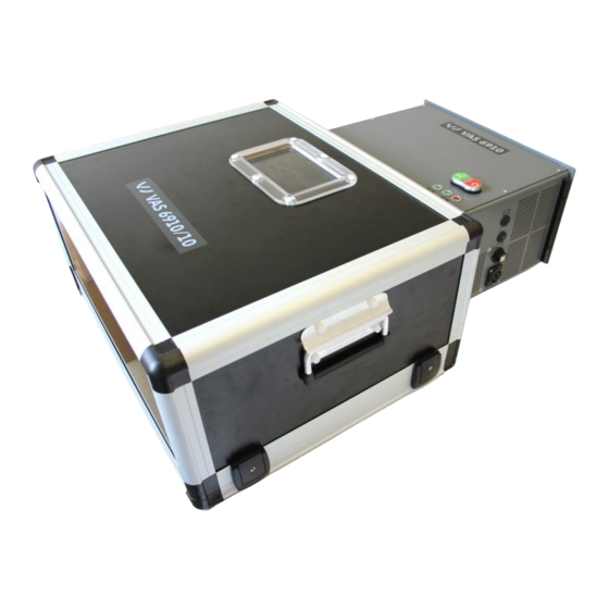
Components Components VAS 6910 Adapter and transport box Adapter and transport box (top view) Fig. 2-1 Adapter and transport box (top view) Window VAS 6910 hardware operating manual V10.00 11/18 All rights reserved. - Page 14 Fig. 2-2 Adapter and transport box (front view) Carrying handle Adapter- and transportation box (side view left/right) Fig. 2-3 Adapter and transport box, closed (side view) Carrying handle Latch Latch VAS 6910 hardware operating manual V10.00 11/18 All rights reserved.
- Page 15 Components Adapter and transport box open with Module-Balancer (top-view) Fig. 2-4 Adapter und transport box open (top view). Carrying handle Module-Balancer Adapter- and transportation box, (bottom part) VAS 6910 hardware operating manual V10.00 11/18 All rights reserved.
- Page 16 Components Adapter and transport box open, Module-Balancer mounted, no cell module (side view) Fig. 2-5 Adapter and transportation box open, side view Module-Balancer Adapter- and transportation box, bottom part VAS 6910 hardware operating manual V10.00 11/18 All rights reserved.
- Page 17 Adapter und transport box open, Module-Balancer attached and cell module inserted, side view. Fig. 2-6 Adapter and transport box open with cell module inserted, side view Cell module Module-Balancer Adapter and transport box (bottom part) VAS 6910 hardware operating manual V10.00 11/18 All rights reserved.
-
Page 18: Vas 6910 Module-Balancer
Components VAS 6910 Module-Balancer VAS 6910 Module-Balancer, rear view Fig. 2-7 VAS 6910 Module-Balancer, rear view Carrying handle VAS 6910 hardware operating manual V10.00 11/18 All rights reserved. - Page 19 Power supply inlet. Connection for power cord WARNING Set up the VAS 6910 so that adequate ventilation is guaranteed, fans and air vents are not obstructed and the air must circulate freely! VAS 6910 hardware operating manual V10.00 11/18 All rights reserved.
- Page 20 The mains cord set must have a C19 plug for the connection to the VAS6910 suitable for the above current ratings. Connect VAS 6910 only to protective contact sockets! Set up the VAS 6910 in a way that there is always free access to the power separator!! (Power cord from the mains socket).
- Page 21 VAS 6910 Module-Balancer, side view left Air inlet grill WARNING Set up the VAS 6910 so that adequate ventilation is guaranteed, fans and air vents are not obstructed and the air must circulate freely! VAS 6910 hardware operating manual V10.00 11/18 All rights reserved.
- Page 22 LED blue Device on and ready blue flashing Device is idle LED red Charging / discharging is running green No charging / discharging active IR temperature sensor VAS 6910 hardware operating manual V10.00 11/18 All rights reserved. 2-10...
- Page 23 Device is on and ready blue blinking Stand-by / idle mode green No Charging / discharging is running Charging / discharging is active or an error has happened. VAS 6910 hardware operating manual V10.00 11/18 All rights reserved. 2-11...
-
Page 24: Cable Sets
2.3.1 USB-Cable (USB 2.0 Fischer to USB 2.0 B Rugged) BV8139, VAS 611003, ASE 611 003 00 000 This USB cable connects the Module Balancer VAS 6910 to the VW Diagnostic system. Free Fischer connector is needed. Fig 2-12 USB-cable USB 2.0 Fischer to USB 2.0 B Rugged 2.3.2... -
Page 25: Basic Cable Set Module Adaption 1 (E-Up!)
6. VAS 6910/10-6 ASE 447 251 00 000 BV8143 Analog-Meas. lead for module variant 12E.915.592.A Usage is on e-UP! 2014 Fig 2-14 Basic cable set Module adaption 1 (e-up!) VAS 6910 hardware operating manual V10.00 11/18 All rights reserved. 2-13... -
Page 26: Extension Cable Set Module Adaption A (E-Golf) Vas 6910/11 Ase 447 241 00 000
Slave Simulation cable for Master-Modules 2. VAS 6910/11-2 ASE 447 258 00 000 BV8146 Analogue meas. cable for Slave-Modules For Volkswagen e-Golf cable sets VAS6910/11 (this one) and the VAS6910/12A are necessary! Start of usage is at e-Golf production year 2014 ff. -
Page 27: Basic Cable Set Module Adaption 2 (Phev)
CAN cable for connecting to the module controller Start of usage is on E-Golf and PHEV from manufacture year 2014 ff. Fig: 2-16 Basic cable set Module adaption 3 (PHEV) VAS 6910 hardware operating manual V10.00 11/18 All rights reserved. 2-15... -
Page 28: Vas 6910/12A Ase 447 242 01 000
- Porsche G1 II PHEV 24 Ah - Porsche E2 II PHEV 28 Ah Start of usage is on Porsche Cayenne and Panamera Hybrid. Adapter cable Porsche G1 II & E2 II PHEV Fig 2-17 VAS 6910 hardware operating manual V10.00 11/18 All rights reserved. 2-16... -
Page 29: Basic Cable Set Module Adaption 4 (Xl1)
Components 2.3.7 Basic cable set Module adaption 4 (XL1) VAS 6910/14 BO7865 Purchase via r XL1 After Sales Volkswagen AG The Basic Cable Set XL 1 consists of three cables: 1. Cable for „plus“ Loose cable clip and M6 knurled nut BV8190 2. -
Page 30: Barcodescanner Vas 6161/1 Ase 447 043 00 000
The scanner is used to scan the bar code attached to the cell modules. The canner has an USB-Type A connector and has to be connected to the VW Diagnostic system (VAS 6150A / VAS 6051B / VAS 6160). Fig. 2-19 2D-Barcodescanner VAS 6910 hardware operating manual V10.00 11/18 All rights reserved. 2-18... - Page 31 1. VAS 6910/16-1 ASE 447 245 00 000 BV8296 CCE Analog connection cable for slave modules 2. VAS 6910/16-2 ASE 447 259 00 000 BV8315 CMC-CCE slave simulation e-Golf 300 GP Basic Cable Fig 2-21 VAS 6910 hardware operating manual V10.00 11/18 All rights reserved. 2-19...
- Page 32 For connection to Audi e-tron (C-BEV), module 4KE.915.591.D, 3S4P „normal“ 2. VAS 6910/17-2 ASE 447 261 00 000 BV8318 For connection to Audi e-tron (C-BEV), module 4KE.915.591.E, 3S4P „mirrored“ Fig 2-2 Basic cable VAS 6910/17 VAS 6910 hardware operating manual V10.00 11/18 All rights reserved. 2-20...
-
Page 33: Scope Of Delivery
AVL-No.: EX7069 ● USB-cable (USB 2.0 A to USB 2.0 B Rugged) VAS 6910/5 VAG-No.: ASE 447 235 00 000 ● AVL-No.: BO7859 Operating manuals and software on CD VAS 6910 hardware operating manual V10.00 11/18 All rights reserved. 2-21... - Page 34 Slave Simulation cable for Master-Modules 2. VAS 6910/11-2 ASE 447 258 00 000 BV8146 Analogue meas. cable for Slave-Modules For VOLKSWAGEN E-Golf both cable VAS 6919/11 and VAS 6910/12A are necessary! VAS 6910 hardware operating manual V10.00 11/18 All rights reserved. 2-22...
- Page 35 CAN cable for connecting to the module controller For PHEV module and for AUDI A3-e-tron ● VAS 6161/1 VAG-Nr.: ASE 447 043 00 000 AVL-Nr.: 2D-bar code reader with USB cable. Distribution Volkswagen AG only! VAS 6910 hardware operating manual V10.00 11/18 All rights reserved. 2-23...
- Page 36 1. VAS 6910/16-1 ASE 447 245 00 000 BV8296 CCE Analog connection cable for slave modules 2. VAS 6910/16-2 ASE 447 259 00 000 BV8315 CMC-CCE slave simulation e-Golf 300 GP VAS 6910 hardware operating manual V10.00 11/18 All rights reserved. 2-24...
- Page 37 The mains cord set must have a C19 plug for the connection to the VAS 6910 suitable for the above current ratings. Connect VAS 6910 only to protective contact sockets! Set up the VAS 6910 in a way that there is always free access to the power separator!! (Power cord from the mains socket).
-
Page 38: Commissioning
Commissioning Commissioning Use the “Unpacking- Start-up and brief instructions” manual for the VAS6910. Firmware-Update To do an update of the VAS 6910 firmware proceed as follows: 1. Start the update program by click on Start│All programs│DiTEST│VAS6910│VAS 6910 Firmware Update. 2. Click the Button twice. -
Page 39: Operation
Operation Operation Preparation Prepare the VAS 6910 for operation. ( chapter. 3 „Commissioning“). 4.1.1 Charging / Discharging 1. Put the cell module (1) to charged/discharged into the adaption box of the VAS6910. Fig. 4-1 Cell module inserted VAS 6910 hardware operating manual V10.00 11/18 All rights reserved. - Page 40 Operation Start│Programs│ 2. Start the VAS Manager by selecting: DiTEST│VAS DSS. Diagnose│Module Balancer. 3. Select Fig. 4-2 DSS Manager 4. The start screen appears: Select Charge/Discharge. Fig. 4-3 Start screen VAS 6910 hardware operating manual V10.00 11/18 All rights reserved.
- Page 41 5. A screen with safety instructions is shown next. WARNING Read and follow the safety instructions carefully! Next. 6. Please read the instructions and confirm by clicking Fig. 4-4 Screen with safety instructions VAS 6910 hardware operating manual V10.00 11/18 All rights reserved.
- Page 42 Operation 7. Please enter your name. (Input user name, see chapter 4.1.6 “Input user name“). Next. 8. Continue by clicking Screen „Enter operator name“ Fig. 4-5 VAS 6910 hardware operating manual V10.00 11/18 All rights reserved.
- Page 43 Choose a cell module type from the drop down list (2) and enter a serial number (3). Input the avg. cell voltage (4). This value is given by the VW Off-board diagnostic system. Next. 10. Confirm by clicking Screen „Select cell module“ Fig. 4-6 VAS 6910 hardware operating manual V10.00 11/18 All rights reserved.
- Page 44 Next. 12. Continue by clicking Click on the button to get a picture schowing where to connect the cable. Screen „Connecting the Cell module“ Fig. 4-7 VAS 6910 hardware operating manual V10.00 11/18 All rights reserved.
- Page 45 Section 1 shows all relevant data. F6 Stop By clicking you can stop the charging / discharging process. Next. 14. After the charging / discharging is finished please click Screen „Charging/ discharging“ Fig. 4-8 VAS 6910 hardware operating manual V10.00 11/18 All rights reserved.
- Page 46 15. A screen appears which shows you how to disconnect the charged / discharged cell module. Please follow the exact order shown. Next. 16. Continue with Screen „Disconnect cell module“ Fig. 4-9 VAS 6910 hardware operating manual V10.00 11/18 All rights reserved.
- Page 47 Starts a print out of the protocol. F5 Edit The protocol can be edited. F8 Next 18. By pressing the charge / discharge process is finished. Screen „Report“ Fig. 4-10 VAS 6910 hardware operating manual V10.00 11/18 All rights reserved.
-
Page 48: Safety Test
Start│Programs│ 1. Start the VAS Manager by selecting: DiTEST│VAS DSS. Diagnose│Module Balancer. 2. Select Fig. 4-11 DSS Manager 3. The start screen appears: Select Safetytest. Fig. 4-12 Start screen VAS 6910 hardware operating manual V10.00 11/18 All rights reserved. 4-10... - Page 49 Operation 4. Follow the on-screen instructions. Next. Continue with Fig. 4-13 Safetytest VAS 6910 hardware operating manual V10.00 11/18 All rights reserved. 4-11...
-
Page 50: Self-Test
Start│Programs│ 1. Start the VAS Manager by selecting: DiTEST│VAS DSS. Diagnose│Module Balancer. 2. Select Fig. 4-14 DSS Manager 3. The start screen appears: Select Selftest. Fig. 4-15 Start screen VAS 6910 hardware operating manual V10.00 11/18 All rights reserved. 4-12... - Page 51 Operation The self-test is performed and the result displayed. Return to the Start screen with Next. Fig. 4-16 Selftest VAS 6910 hardware operating manual V10.00 11/18 All rights reserved. 4-13...
-
Page 52: Deviceinfo
Start│Programs│ 1. Start the VAS Manager by selecting: DiTEST│VAS DSS. Diagnose│Module Balancer. 2. Select Fig. 4-17 DSS Manager 3. The start screen appears: Select Deviceinfo. Fig. 4-18 Start screen VAS 6910 hardware operating manual V10.00 11/18 All rights reserved. 4-14... - Page 53 Operation A screen appears with the device data. With F8 Next to the home screen. Fig. 4-19 Deviceinfo VAS 6910 hardware operating manual V10.00 11/18 All rights reserved. 4-15...
-
Page 54: Viewing All Reports
Select Proof / Diagnosis Logs etc. Search text Choose between “None”, “Manufacturer” or “Licence number”. In the Search text field, you can narrow the selection down further. Return to “Results Management” with Quit. VAS 6910 hardware operating manual V10.00 11/18 All rights reserved. 4-16... - Page 55 The archived logs will be deleted from the internal database. F5 Directory Opens a window to choose the save location. Choose a location and then click OK. F8 Next Starts the archiving. << Cancel Quits the results display. VAS 6910 hardware operating manual V10.00 11/18 All rights reserved. 4-17...
-
Page 56: Result Report Directory
Result report directory Result protocols are stored for future use at the default location: “C:\Users\Public\Documents\xxxx“. This location can be changed: ExtrasSettingsAVL DiGate480. Click on Fig. 4-11 Changing the Report protocol directory VAS 6910 hardware operating manual V10.00 11/18 All rights reserved. 4-18... -
Page 57: Entering A List Of Operator Names
Switch off The VAS 6910 has no on/off switch. With the button, see fig. 2-8, only the power modules are switched off. The VAS 6910 enters Idle, Sleep mode. To disconnect the VAS 6910 from the power grid press the red button (Power module off) and disconnect the power cable from the wall outlet. -
Page 58: Troubleshooting
Troubleshooting Troubleshooting Maintenance DANGER Danger to life by electrical shock Maintenance is only allowed by service staff! Do not open the VAS 6910, because exposed parts can have dangerous voltages! VAS 6910 hardware operating manual V10.00 11/18 All rights reserved. -
Page 59: Maintenance And Care
Maintenance and care Maintenance and care Optical check Carry out a regular optical check of the VAS 6910, USB cable and measuring cables with the test adapters. Check for damage and dirt. CAUTION Damaged Parts (power cord, adapter and US cables) have to be exchanged... -
Page 60: Technical Data
Measurement device: DIN EN 61010-1 (VDE 0411 part 1) IEC 1010-1 Garage equipment: UL 201 GARAGE-EQUIPMENT - Protection class I - Degree of protection IP30 - Degree of contamination II VAS 6910 hardware operating manual V10.00 11/18 All rights reserved. -
Page 61: Fault Report Fax
Fax. 1. As to be entered / already entered on the tester (see Operating Manual) 2. For EU countries only Please provide additional information as requested on the following page. VAS 6910 hardware operating manual V10.00 11/18 All rights reserved. - Page 62 Yes ❏ Does the fault occur sporadically? What software firmware versions are you running? (Choose from VAS-Manager Service/Maintenance>System-info>without devices) Module Balancer: Please provide additional information as requested on the following page. VAS 6910 hardware operating manual V10.00 11/18 All rights reserved.
- Page 63 Does the fault report fax have any attachments? Yes ❏ Screenshot with error messages? We have read the service conditions for the replacement of components and we hereby accept these conditions. City Date Signature Stamp VAS 6910 hardware operating manual V10.00 11/18 All rights reserved.
-
Page 64: Index
Fault report fax 8-1 Switch off 4-16 Field of application 1-4 Technical data 7-1 General Information 1-1 Troubleshooting 5-1 General Notes 1-1 VAS 6910 Module-Balancer 2-6 Viewing all reports 4-12 VAS 6910 hardware operating manual V10.00 11/18 All rights reserved. - Page 65 Subject alteration. All rights reserved. Manufacturer: VOLKSWAGEN AG AVL DiTEST GmbH KD-WERKSTATTAUSRÜSTUNG Alte Poststrasse 156 D-38436 Wolfsburg 8020 Graz AUSTRIA Copyright Volkswagen AG 2018, AVL DiTEST 2018 All rights reserved. VAS 6910 hardware operating manual V10.00 11/18 All rights reserved.
Need help?
Do you have a question about the VAS 6910 and is the answer not in the manual?
Questions and answers