Table of Contents
Advertisement
Quick Links
Advertisement
Table of Contents

Related Manuals for Cognex DMA-EZCCM-001


Summary of Contents for Cognex DMA-EZCCM-001
- Page 1 DMA-EZCCM-001 User Guide 2019 October 08 Revision: 6.1.6SR1.9...
-
Page 3: Legal Notices
Copyright © 2019. Cognex Corporation. All Rights Reserved. Portions of the hardware and software provided by Cognex may be covered by one or more U.S. and foreign patents, as well as pending U.S. and foreign patents listed on the Cognex web site at: cognex.com/patents. -
Page 4: Table Of Contents
Table of Contents Table of Contents Legal Notices Table of Contents Symbols About DMA-EZCCM-001 Product Description Functional Principle Supported DataMan Readers Multiprotocol Functionality Indicator LEDs Module LED Status I/O LEDs Dimensions Accessories Mounting Grounding Connecting Supply Concept Connecting the modules to Ethernet... - Page 5 Table of Contents Disposal Appendix DMA-EZCCM-001 Specifications Precautions Regulations/Conformity Product Identification Scope of Delivery Legal Requirements Safety Intended Use General Safety Instructions...
-
Page 6: Symbols
Symbols Symbols The following symbols indicate safety precautions and supplemental information: WARNING: This symbol indicates a hazard that could cause death, serious personal injury or electrical shock. CAUTION: This symbol indicates a hazard that could result in property damage. Note: This symbol indicates additional information about a subject. Tip: This symbol indicates suggestions and shortcuts that might not otherwise be apparent. -
Page 7: About Dma-Ezccm-001
About DMA-EZCCM-001 About DMA-EZCCM-001 Product Description The DMA-EZCCM-001 is a communication module for DataMan readers, which supports daisy chaining over Industrial Ethernet. This device is developed in cooperation with the company Turck. DMA-EZCCM-001 provides the following features: Data Exchange via Multiprotocol functionality Ethernet/IP™ Device or PROFINET IO Device... -
Page 8: Indicator Leds
About DMA-EZCCM-001 PROFINET EtherNet/IP™ A multi-protocol device can be operated without intervention from the user (which means, without changes in the parameterization) in both Ethernet protocols mentioned. During start-up, after a power-on, the module runs in "snooping" mode and detects the Ethernet protocol which requests a link connection by listening to the traffic. - Page 9 About DMA-EZCCM-001 Color Status Description IN1/IN2 GREEN Input active Flashing Overload of the port supply. Both LEDs of the corresponding port are flashing. Input of output inactive C3/IN2 WHITE Flashing Blink/Wing command active...
-
Page 10: Dimensions
About DMA-EZCCM-001 Dimensions Note: All dimensions are in millimeters [inches] and are for reference purposes only. All specifications are for reference purpose only, and may be changed without notice. Accessories Dataman Cable for DM70 & DM150 - 3 meter* DMCB-EZCCM-DB15-03 *use also DMA-SERIAL-IP65-ST in combination with DM70 Dataman Cable for DM260, DM300 &... -
Page 11: Mounting
1. Unlock the cover flap with a flat tool (e.g. screw driver). 2. Open the flap completely. 3. To join the DMA-EZCCM-001 module and the spacer, insert the key of the spacer into the slot of the DMA- EZCCM-001 module. - Page 12 Orient the spacers so that the arrow in the cover flap of every spacer points in direction to the M8 Ethernet connectors Connect the grounding contact of the spacer to the grounding contact of the device TBNN-SO-DRS is not a Cognex accessory, please contact Turck for more information.
- Page 13 About DMA-EZCCM-001 1. Unlock the cover flap with a flat tool (e.g. screw driver). 2. Open the flap completely. 3. To join the EZCCM-module and the spacer, insert the key of the spacer into the slot of the EZCCM-module (3).
-
Page 14: Grounding
Grounding Grounding and Shielding Concept Field bus and I/O part of the DMA-EZCCM-001 modules can be grounded separately. 1. The grounding clamp at the M8 connectors for the fieldbus connection (P1, P2) connects the shield of the fieldbus lines. - Page 15 About DMA-EZCCM-001 4. The spacers TBNN-S0-DRS for mounting the DMA-EZCCM-001 modules onto a DIN rail (TS 35) connect the grounding contact of the modules with the DIN rail and thus with FE. Ground the Device (FE) To shield the network cables from possible noise interference the flange of the M8 connectors needs to be at the reference potential of the installation.
-
Page 16: Connecting
Connecting Supply Concept All DMA-EZCCM-001 modules are supplied via two separate voltages V1 and V2. The I/O-channels are separated into the different potential groups. This allows a safety shutdown of parts of an installation via emergency-off circuits. V1 = supply for DataMan Readers... -
Page 17: Connecting Power Supply
X1and X2). Interchanging the Ethernet and the power cables can destruct the internal electronics. Connect the device to Ethernet according to the pin assignment below. Connecting Power Supply The DMA-EZCCM-001 module is provided with two 4-pin M8 plug connectors for connecting the power supply. V1 and V2 are galvanically isolated. CAUTION: Observe using the correct M8-connectors when connecting Ethernet- and power cables (Ethernet: P1 and P2, power: X1 and X2). -
Page 18: Connecting Digital Sensors
Connecting Digital Sensors The DMA-EZCCM-001 module is provided with two 5-pin M12 connectors for connecting digital sensors, which can act as trigger to the DataMan readers or general inputs to read out via fieldbus. Connect the sensors to the device according to the pin assignment shown below. -
Page 19: Connecting Dataman Readers
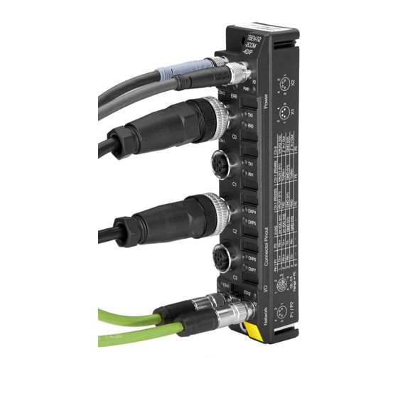
GND V2 IN 1 Connecting DataMan Readers The DMA-EZCCM-001 module is provided with two 5-pin M12 connectors for connecting DataMan Readers. Connecting DataMan 70 Series To connect a DataMan 70 series reader to the DMA-EZCCM-001, two cables are required: DMA-SERIAL-IP65-ST... - Page 20 About DMA-EZCCM-001 Connecting DataMan 260 / 300 / 470 Series To connect DataMan 260, 300 or 470 Series a connection accessory is required. DMCB-EZCCM-M12-03 The image shows a connection to a DataMan 260 reader.
-
Page 21: Getting Started
In the right pane configure the IP details for the device Setup Tool Connection Each DMA-EZCCM-001 can control two DataMan readers, which are automatically added to the list when a module is discovered. When connecting to the device, Setup Tool tunnels through the DMA-EZCCM-001 to the DataMan reader. -
Page 22: Web Gui
Getting Started Web GUI When double clicking the discovered Daisy chain device, your default browser will open and show you a webserver link of the device. Here you have the possibility to see the details and data structure of the device. A separate view with the "Dataman Reader Status"... - Page 23 Getting Started...
-
Page 24: Memory Mapping
Getting Started Memory Mapping The memory mapping consists of two blocks of which size will be variable depending on the data block size: Input is viewed from PLC perspective and shows data from DMA-EZCCM-001 -> PLC Status Result Data Total Size... - Page 25 Getting Started Byte Description Description Comment 0 = Not Ready to Accept Trigger via Fieldbus (state Trigger Ready when Trigger Enable is low or currently processing trigger or soft event) 1 = Ready to Accept new Trigger via Fieldbus Trigger Ack Confirmation of receiving Trigger ON bit, stays on until Trigger bit is low 0 = Reader Idle...
- Page 26 Size ACK 0 = Reader 2 Enabled (default) Reader 2 Disabled 1 = Reader 2 Disabled 8 ... ResultData Output is viewed from PLC perspective and shows data from PLC -> DMA-EZCCM-001 Control User Data Total Size 16 bytes 24 bytes...
-
Page 27: Setup Device
Byte Ch2/64 Byte Ch2/136 Byte Ch2/232 Identify Reader Connection Setup Tool will automatically broadcast to find the DMA-EZCCM-001 over the network The “Serial error” bit in “Trigger Status” byte will indicate when the reader is down or the connection is broken. -
Page 28: Triggering Readers
Getting Started Triggering Readers Trigger via Photoeye: Port C2 corresponds to C0 input of the reader. Port C3 corresponds to C1 input of the reader. Each port has two different physical inputs that can be used PIN 2 / PIN 4. This selection can be made with “Trigger PIN”... -
Page 29: Soft Events
Getting Started Soft Events Soft events let the user access the advanced functionality of the reader through special commands that allow access to internal data and parameters of the readers: Train Code – triggers the reader and trains the read code; Train Match String –... -
Page 30: Advanced Features
Reading Input Channel The DMA-EZCCM-001 has two input channels and each has 2 input lines, on pin 2 and pin 4. Each of the 4 inputs can be traced back to the PLC so that it tracks any signals coming from the conveyor. -
Page 31: Connecting
Used Software The following software tools are used in this example: SIMATIC TIA Portal V13 GSDML file for DMA-EZCCM-001 will be included in the install files of Setup Tool Prerequisites The programming software has been started. A new project has been created. - Page 32 2. Select the GSDML-file to be installed and click "Install". As a result, the device is added to the Hardware catalog of the programming software. 3. Select the DMA-EZCCM-001 from the Hardware catalog and drag it into the "Device & net-works" editor. 4. Configure the device per drag & drop depending on the application.
-
Page 33: Slots And Modules
Connecting Slots and Modules The DMA-EZCCM-001 has a head module and two slots where you can add different sizes of INPUT and OUTPUT modules. Connect the device to the PLC in the Devices & networks editor. - Page 34 Connecting Perform the following steps to assign a PROFINET device name: 1. Select "Online access" -> "Online & diagnostics". 2. Select "Functions" -> „Assign name”. 3. Enter the desired PROFINET device name for the device. Setting the IP address in TIA Portal:...
-
Page 35: Connecting The Device To An Ethernet/Ip™ Plc
Connecting 1. Select the DMA-EZCCM-001 in the "Device view". 2. Select "Ethernet addresses" in the register tab "Properties". 3. Assign the desired IP address. Connecting the device to an EtherNet/IP™ PLC The following hardware components are used in this example::... - Page 36 Connecting Adding the Prebuilt Generic Ethernet modules Import the L5K detailed project or open the ACD sample project to find all variation of setups of daisy chain devices. Connecting the device to the PLC: Drop down the “Ethernet” connections in “I/O Configuration” mapping. Drag and drop the type of configuration you need into your project.
- Page 37 Connecting Data blocks Data memory Input...
- Page 38 Connecting Data memory Output...
- Page 39 Connecting...
-
Page 40: Troubleshooting
Troubleshooting Troubleshooting If the device does not function as expected, first check whether ambient interference is present. If there is no ambient interference present, check the connections of the device for faults. If there are no faults, there is a device malfunction. In this case, decommission the device and replace it with a new device of the same type. -
Page 41: Maintenance
The devices are maintenance-free. Clean the devices with a dry cloth, if required. Firmware Update The device firmware can be updated via Cognex DataMan Setup Tool and the latest version is included in the installer. CAUTION: Do not reset or interrupt the power supply during firmware update, as faulty firmware update can damage the device."... -
Page 42: Appendix
Appendix Appendix Possible Network Structures: Network Structure Example 1:... - Page 43 Appendix Network Structure Example 2: Network Structure Example 3:...
- Page 44 Daisy Chain – Maximum Number of Connected Modules Prerequisites: Optimized network Only DMA-EZCCM-001 modules in the daisy chain, no additional switches, no third-party devices Exchange of pure process data, no acyclic data Cable length between the DMA-EZCCM-001 modules max. 50 m...
- Page 45 Single DataMan 150 / 260 per DMA-EZCCM-001 Dual DataMan 150 / 260 per DMA- EZCCM-001 Single DataMan 300 / 470 with HPIA per DMA-EZCCM-001 Dual DataMan 300 / 470 with HPIA per DMA-EZCCM-001 Note: DataMan 300 / 470 with HPIL is not supported.
-
Page 46: Dma-Ezccm-001 Specifications
DMA-EZCCM-001 Specifications DMA-EZCCM-001 Specifications Supply Voltage 24VDC -40…+70 °C Operating temperature Storage temperature -40…+85 °C 18-30VDC Permissible Range Total current: maximum 4A per voltage group Total current V1+V2: maximum 5.5 A at 70 °C per module max. 5000 m Operating altitude... - Page 47 DMA-EZCCM-001 Specifications PROFINET Diagnostics according to PROFINET Alarm Handling supported Topology discovery supported Media Redundancy Protocol (MRP) Cable length max. 30 m DataMan interface Signal type RS232 Number of channels Operation mode RS232 -18…-3 VDC Signal low level Signal high level 3…18 VDC...
-
Page 48: Precautions
Precautions Precautions To reduce the risk of injury or equipment damage, observe the following precautions when you install the Cognex product: Route cables and wires away from high-current wiring or high-voltage power sources to reduce the risk of damage or malfunction from the following causes: over-voltage, line noise, electrostatic discharge (ESD), power surges, or other irregularities in the power supply. -
Page 49: Regulations/Conformity
The product is designed according to state-of-the-art technology. However, residual risks still exist. Observe the following warnings and safety notices to prevent damage to persons and property. Cognex accepts no liability for damage caused by failure to observe these warning and safety notices. - Page 50 Copyright © 2019 Cognex Corporation. All Rights Reserved.
Need help?
Do you have a question about the DMA-EZCCM-001 and is the answer not in the manual?
Questions and answers