Water Right IMP-844 Installation Instructions & Owner's Manual
Metered water softener
Hide thumbs
Also See for IMP-844:
- Installation instructions and owner's manual (32 pages) ,
- Installation instructions & owner's manual (32 pages) ,
- Installation instructions & owner's manual (28 pages)

Related Manuals for Water Right IMP-844


Summary of Contents for Water Right IMP-844
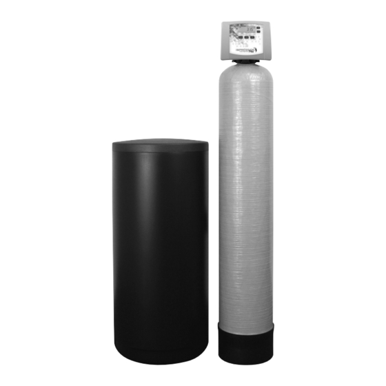
- Page 1 Impression Plus Series ® Metered Water Softeners For Certified Models: • IMP-844 • IMP-948 • IMP-1044 • IMP-1054 • IMP-1248 • IMP-1354 Certified Cabinet Models: • IMPC-835 • IMPC-935 • IMPC-1035...
-
Page 2: Table Of Contents
TABLE OF CONTENTS Pre-Installation Instructions for Dealers . . . . . . . . . . . . . . . . . . . . . . . . . . . . . . . . . . . . . . . . 3 Bypass Valve . -
Page 3: Pre-Installation Instructions For Dealers
PRE-INSTALLATION INSTRUCTIONS FOR DEALERS The manufacturer has preset the water treatment unit’s sequence of cycles and cycle times. The dealer should read this page and guide the installer regarding hardness, day override, and time of regeneration, before installation. For the installer, the following must be used: •... -
Page 4: Bypass Valve
BYPASS VALVE The bypass valve is typically used to isolate the control valve from the plumbing system’s water pressure in order to perform control valve repairs or maintenance. The 1” full flow bypass valve incorporates four positions, including a diagnostic position that allows a service technician to have pressure to test a system while providing untreated bypass water to the building. -
Page 5: Installation
INSTALLATION GENERAL INSTALLATION & SERVICE WARNINGS The control valve, fittings and/or bypass are designed to accommodate minor plumbing misalignments. There is a small amount of “give” to properly connect the piping, but the water softener is not designed to support the weight of the plumbing. Do not use Vaseline, oils, other hydrocarbon lubricants or spray silicone anywhere. - Page 6 INSTALLATION should be set before installing the nut, split ring and “O” Ring. Avoid getting solder flux, primer, and solvent cement on any part of the “O” Rings, split rings, bypass valve or control valve. If the building’s electrical system is grounded to the plumbing, install a copper grounding strap from the inlet to the outlet pipe.
-
Page 7: Installation
INSTALLATION 9. SAFETY BRINE TANK CONNECTION: Install the 3/8” O.D. polyethylene tube from the Refill Elbow to the Brine Safety Float valve in the brine tank. Connection at Refi ll Elbow on the control valve Connection at Brine Safety Float in brine tank 10. -
Page 8: Programming Procedures
PROGRAMMING PROCEDURES 1. Set time of day: Time of day should only need to be set after extended power outages or when daylight saving time begins or ends. If an extended power outage occurs, the time of day will flash on and off indicating that the time should be reset. STEP 1 –... -
Page 9: Startup Instructions
FOR DOWNFLOW REGENERATING UNITS STARTUP INSTRUCTIONS FLUSHING OF SYSTEM: To flush the system of any debris and air after installation is complete, please perform the following steps: 1. Rotate bypass handles to the bypass mode (Fig. 2 on page 4) . 2. -
Page 10: Operating Displays And Maintenance
OPERATING DISPLAYS AND MAINTENANCE 1. GENERAL OPERATION: When the system is operating, one of four displays may be shown and will alternate with the installing dealer’s name and phone number for future service. Pressing will alternate between the displays. NEXT 1. - Page 11 OPERATING DISPLAYS AND MAINTENANCE 4. POWER LOSS AND BATTERY REPLACEMENT: If an extended power outage BATTERY REPLACEMENT occurs, the control valve will retain the time of day settings until the board’s battery is depleted. Once the battery is depleted, the display will appear dark and absent of any information.
-
Page 12: Troubleshooting Guide
TROUBLESHOOTING GUIDE PROBLEM CAUSE CORRECTION A. No power at electric outlet A. Repair outlet or use working outlet B. Control valve power adapter not plugged into B. Plug power adapter into outlet or connect outlet or power cord end not connected to PC power cord end to PC board connection board connection 1. - Page 13 TROUBLESHOOTING GUIDE PROBLEM CAUSE CORRECTION A. Turn bypass handles to place bypass in A. Bypass valve in bypass position service position 7. Control valve does not B. Meter is not connected to meter connection on B. Connect meter to three pin connection labeled regenerate automatically PC board METER on PC board...
- Page 14 TROUBLESHOOTING GUIDE PROBLEM CAUSE CORRECTION A. Injector is plugged A. Remove injector and clean or replace B. Faulty regenerant piston B. Replace regenerant piston C. Regenerant line connection leak C. Inspect regenerant line for air leak 12. Control valve fails to D.
- Page 15 TROUBLESHOOTING GUIDE PROBLEM CAUSE CORRECTION A. Check motor connections then Press NEXT and REGEN buttons for 3 seconds to resynchronize A. Motor failure during a regeneration software with piston position or disconnect power supply from PC board for 5 seconds and then reconnect.
- Page 16 TROUBLESHOOTING GUIDE PROBLEM CAUSE CORRECTION 20. Err – 109 A. Invalid motor state detected A. Replace PC board 21. Err – 201 A. Invalid regeneration cycle step detected A. Replace PC board A. Check for low flow leak. Press NEXT and A.
- Page 17 This page left intentionally blank.
-
Page 18: Replacement Parts
REPLACEMENT PARTS FRONT COVER AND DRIVE ASSEMBLY Item No. Part No. Description Qty. CV3540-A Black Impression cover ® CV3540-W-A Gray Impression cover ® CV3540P-A Black Impression Plus cover ® CV3540P-W-A Gray Impression Plus cover ® CV3107-1 Motor Drive bracket & spring clip CV3002A (Includes #5, #6) CV3579WI... - Page 19 REPLACEMENT PARTS PISTON ASSEMBLY Item No. Part No. Description Qty. CV3005 1” spacer stack assembly CV3430 1.25” spacer stack assembly CV3004 Drive cap assembly CV3135 O-ring 228 CV3011 1” piston assembly downflow CV3011-01 1” piston assembly upflow CV3407 1.25” piston assembly downflow NOTE: Optional On Some Models Only.
- Page 20 REPLACEMENT PARTS BYPASS VALVE Item No. Part No. Description Qty. CV3006 Bypass assembly CV3147 Bypass handles BRINE ELBOW ASSEMBLY Item No. Part No. Description Qty. CV3195-01 Refill port plug assembly CH4615 Elbow locking clip CV4144 3/8” Elbow, Parker fitting CV3163 O-ring 019 Loosens Injector And Bypass Caps...
- Page 21 REPLACEMENT PARTS INJECTOR ASSEMBLIES Item No. Part No. Description Qty. CV3176 Injector cap CV3152 O-ring 135 CV3177-01 Injector screen CV3010-1Z Injector assembly plug CV3010-1A A injector assembly, BLACK CV3010-1B B injector assembly, BROWN CV3010-1C C injector assembly, VIOLET CV3010-1D D injector assembly, CV3010-1E E injector assembly, WHITE...
- Page 22 REPLACEMENT PARTS DRAIN LINE ASSEMBLY 3/4” DRAIN LINE ASSEMBLY 1” Item No. Part No. Description Qty. Item No. Part No. Description Qty. CH4615 Elbow locking clip CH4615 Elbow locking clip CPKP10TS8-BULK Optional insert, 5/8” tube CV3166 Drain FTG body 1 CV3192 Optional nut, 3/4”...
- Page 23 REPLACEMENT PARTS BRINE TANK ASSEMBLY Item No. Part No. Description Qty. CG2191- 84 Brine tank cover, injection molded WR CG2180 Brine tank cover, standard CH1095-01 Optional 18” diameter salt grid CH1080 Optional 24” diameter salt grid CG21833CB1C00 18” x 33” brine tank, black CG21840CB1C00 18”...
- Page 24 REPLACEMENT PARTS CABINET AND BRINE TANK Item No. Part No. Description Qty. CJ2TCWS-HEH Top Assembly Light Gray/Dark Gray CJ2B35E Bottom Assembly Light Gray with 474 Brine Assembly Not shown CH4850-34.625 Brine Well with Brine Well 474 Assembly 34 ”...
- Page 25 This page left intentionally blank.
-
Page 26: Installation Fitting Assemblies
INSTALLATION FITTING ASSEMBLIES NOTE: Not all available fi ttings are displayed below. Contact manufacturer for optional fi ttings. 1” PVC MALE NPT ELBOW 3/4” & 1” PVC SOLVENT ELBOW Item Item Part No. Description Qty. Part No. Description Qty. CV3007 1”... -
Page 27: Installation Fitting Assemblies
INSTALLATION FITTING ASSEMBLIES NOTE: Not all available fi ttings are displayed below. Contact manufacturer for optional fi ttings. 1-1/4” & 1-1/2” BRASS SWEAT 1-1/4” & 1-1/2” PVC SOLVENT Item Item Part No. Description Qty. Part No. Description Qty. CV3007- 09 1-1/4 &... -
Page 28: Specifications
Impression Plus Series ® Specifications SPECIFICATIONS IMP SPECIFICATIONS MODEL IMP-844 IMP-948 IMP-1044 IMP-1054 IMP-1248 IMP-1354 Minimum 13,700 @ 3.4 18,200 @ 4.5 18,200 @ 4.5 27,600 @ 7.0 36,400 @ 9.0 45,800 @ 11.5 Rated Softener Capacity:* Medium 16,800 @ 6.0 23,500 @ 9.0... -
Page 29: Warranty
Water Softener Limited Warranty Congratulations. You have purchased one of the nest water treatment systems available. In the unlikely event of a problem due to defects in material and workmanship, we proudly warrant our water softeners to the original owner, when installed in accordance with Water-Right speci cations. -
Page 30: Quick Reference Guide
QUICK REFERENCE GUIDE GENERAL OPERATION ERROR When the system is operating, one of four displays will be shown: CALL FOR SERVICE If the display toggles between “Error” 1. time of day/gpm ERROR and an error code (i.e. a number), call 2. - Page 31 This page left intentionally blank.
- Page 32 1900 Prospect Court • Appleton, WI 54914 © 2018 Water-Right, Inc. All rights reserved. Phone: 920-739-9401 • Fax: 920-739-9406 MAN-IMP CERT RevA0818...
Need help?
Do you have a question about the IMP-844 and is the answer not in the manual?
Questions and answers