Table of Contents
Advertisement
Quick Links
Advertisement
Chapters
Table of Contents

Summary of Contents for Barudan BEVT Series
- Page 1 B E V T Instruction Manual...
-
Page 2: Table Of Contents
Table of Contents Chapter 1. Safety Instructions 1. The safety Instructions on Use …………………………………………… 1 - 2 2. Grounding Instrustions ……………………………………………………… 1 - 5 3. Warning Labels ……………………………………………………………… 1 - 5 Chapter 2. Introduction 1. Specification ……………………………………………………………… 2 - 2 2. - Page 3 Chapter 6. USB Memory 1. Before Using USB Memory ………………………………………………… 6 - 2 2. The Files in the USB Memory …………………………………………… 6 - 5 3. Creating Folders in the USB Memor …………………………………… 6 - 6 4. Saving to the USB Memory ………………………………………………… 6 - 8 5.
- Page 4 Chapter 11. MC (Machine Condition) 1. The MC Change ……………………………………………………………… 11 - 2 2. MC Reset …………………………………………………………………… 11 - 4 3. MC List ……………………………………………………………………… 11 - 5 Chapter 12. Network 1. Before Using the Network System ……………………………………… 12 - 2 2.
-
Page 5: Chapter 1. Safety Instructions
Chapter 1. Safety Instructions This chapter contains information on the following. 1. Safety Instructions 2. Grounding Instrustions 3. Warning Labels 1-1... - Page 6 1. Safey Instructions Before using the machine make sure to read this manual thoroughly and follow all instructions. The icons in the manual show the importance of the contents. Acknowledge the following descriptions beforehand. Icons Safety information abou Warning ! Protecting yourself.
- Page 7 Warning ! Follow the electrical specifications instructed. Do not modify or dismantle the machine. It can cause fire or malfunction. Connect this embroidery machine to a properly grounded outlet only. Connect the power plug firmly. Incorrect contact to the power plug may cause electrical shock.
- Page 8 Residual power may cause electric shock. Wait for 4 minutes before opening the cover. Some parts in the controller can be very hot. Be sure not to burn your hands. Use only attachments and parts recommeneded by Barudan. Wrong parts can damage the machine.
-
Page 9: Warning Labels
3.Warning Labels GPay attention during operation to the parts labeled. Warning Labels Contents Needle Hazard Warning Lable Hair Warning Label Take-Up Lever Warning Label Frame Warning Label Hook Warning Label Belt Warning Label 1-5... -
Page 10: Chapter 2. Introduction
Chapter 2. Introduction This chapter contains the following information. 1. Specification 2. Advantage 2-1... -
Page 11: Specification
1. Specification 1) Design Capacity/Stitch Capacity : 30 designs /10 million stitches 2) Display : LCD 320 x 240 16bit Color LCD 3) Power Source : AC100V Single AC200V Single (+/-10%, 50/60Hz) 4) Power Consumption : 1KVA /Varies for each model 5) Temperature : 5 –... -
Page 12: Advantage
2.Advantage 1) Easy Operation The controller has a microcomputer and is designed for an embroidery machine. More reliable than multipurpose control system. Graphic User Interface with icons makes operating the machine easy. 2) High Speed Drive The microcomputer chooses most efficient speed automatically(200-1200rpm). *Max. - Page 13 12) Other Functions a. The controller allows cycle embroidery 1-200 or infinite (Setting : 201) b. Automatic design conversion for socks. c. Automatic layout for the Matrix embroidery Creates a pattern arrangement controlling the number of times a pattern will sew horizontally and vertically and amount of space between each. d.
-
Page 14: Chapter 3. Before Use
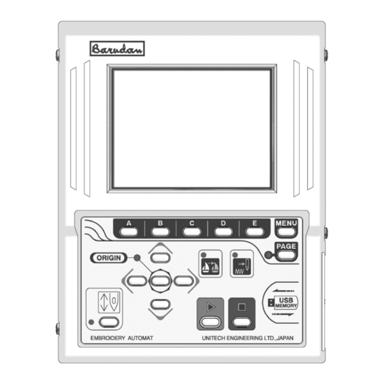
Chapter 3. Before Use This chapter includes information on the following topics. 1. Automat 2. Turning ON /OFF the Machine 3. Origin Setting 4. Stand-by and Drive State 5.Switching Menu Icon Keys 6. Switching Screens 7. The Information on the Screen 8. - Page 15 1. Automat ① ② ⑦ ② ⑥ ③ ⑪ ⑫ ⑩ ⑧ ⑨ ⑤ ④ ⑬ ⑭ ⑮ 3-2...
- Page 16 1. LCD Display Shows machine status, icons, design information *Refer to “Contents on the display” 2. Icon key – the A, B, C, D, E-keys The operation buttons assigned to functions displayed by icons. 3. Origin LED When lit the pantograph is located at the origin. Blinks when the Jog Keys are assigned to other functions.
- Page 17 When the machine is initially turned on the origin must be set. 1) Refer to “Turning ON/OFF the machine, turn ON the machine. 2) The display shows the screen below after showing BARUDAN logo. Press the E-Key to move back the pantograph to the origin.
- Page 18 4.Stand-By and Drive Mode The machine has two mode Stand-By, when it is not in a sewing mode but turned on and the Drive mode, ready to begin sewing. Refer to “Drive” in “Start Sewing”. 1) Stand-By mode : Usually machine is in the stand-by state when it is turned ON. It is the state when sewing preparation takes place.
- Page 19 5.Menu Keys 5-1.Switching Menus Menu keys (A - E) correspond to the icon commands directly above them on the LCD. The Menu key moves to the next set of commands. The icons change accordingly, while advancing though the various functions. Press the menu key, to display the next set of commands (Menu 1 and Menu 2) are displayed as shown below.
- Page 20 Memory Key Shows designs in the memory and CF card. Outputs the design. Shows drive mode. Teach Key Lists the color change codes in the design and allows them to be changed. Float Key Moves the pantograph through the design with stitich it. Network Key Reads design data from the server.
- Page 21 3) Extension Screen 2 Press Page Key twice to show the extension page 2. It shows the design and current needle location as it is sewing, the machine speed, and the total stitch count. The Page Key shows the Basic Screen. Going back to the Stand-By mode automatically switches the screen to the Basic Screen.
- Page 22 2. Design Name. 3. Programmed Rotation. (Can be changed in the Drive Condition Menu) 4. Programmed Repeats set in the Drive Condition. 5. Indicates the correct stop position when it shows “TOP”. 6. Indicates the needle No. Shows “NO” when the position of the needle is incorrect. 7.
- Page 23 1. Shows the stitch count where the next color change exists and the needle No. 2. Shows estimated run time and max. speed. The run time is calculated from the remaining stitches and the sewing speed. This is an estimated run time. 3.
-
Page 24: Messages
9. Messages Error messages display during operation display at the bottom of the basic screen. For example, the figure below shows the error message for a thread break. Messages (A-Key) (B-Key) (C-Key) (D-Key) (E-Key) Clearing the message Press the E-Key or the Page Key to clear the message. The A to D-Key are not available while a message appears on the screen. - Page 25 11. Setting Colors on the Display 11-1. Jog Key operation The Jog Keys move the cursor through the list. Choose a column with up / down key。 Left / Right key switch the page The Jog Key chooses the color on the display. Move Up / Down the cursor with Up/Down Key Move Left / Right the cursor 11-2.
- Page 26 5) Press the A-Key. (A-Key) (B-Key) (C-Key) (D-Key) (E-Key) 6) The Color Set-Up Menu displays. Use the Jog Keys to select a color. Color for the chosen item The screen thumbnail Set Color for Each Item (A-Key) (B-Key) (C-Key) (D-Key) (E-Key) 7) Choose the item.
- Page 27 9) The color chart displays. Use the Jog Keys to select a color. The Color Chart (A-Key) (B-Key) (C-Key) (D-Key) (E-Key) A-Key to goes back to previous screen. Press the E-Key to save the change and go back to previous screen. 10) Press the MENU Key to go out from the Color Set-Up Menu.
- Page 28 11-3. Initializing the Color Initializing the color display. 1) refer to “Changing the Color in the Display” and find the Color Set-Up Menu. 2) Press and hold the E-Key for 2 short beeps. (A-Key) (B-Key) (C-Key) (D-Key) (E-Key) 3) Press the A-Key to start initialization. (A-Key) (B-Key) (C-Key)
- Page 29 11-5.Changing Memory Design Color( ) Color Edit List the color for each code. * Changes the color of the memory design bitmap and visual display. 1) Refer to “Changing the Color in the Display” and go to the color Setup Menu. 2) Press the C-Key.
- Page 30 5) Change the color. Use the jog key and choose 3 primary colors, “R””G””B”. Original color 3 primary colors New color 6) Change the value using the A/B-Keys. The color pallet color changes depend on the entered value. Original color New color (A-Key) (B-Key)
- Page 31 8) Press the C-Key to save the new color to the memory. *The bitmap image of the chosen memory design on the memory design control screen will be re-written with the new colors. (A-Key) (B-Key) (C-Key) (D-Key) (E-Key) If you do not want to save the new color to the memory, press the MENU Key to skip the Color setting screen.
- Page 32 4) Press the E-Key. (A-Key) (B-Key) (C-Key) (D-Key) (E-Key) 5) Use the jog key and choose a new color to change to. Current Color New Color (A-Key) (B-Key) (C-Key) (D-Key) (E-Key) Press the A-Key to change the color switching function icon. Interchange The chosen one will be shown on the right.
- Page 33 (A-Key) (B-Key) (C-Key) (D-Key) (E-Key) If you do not want to save the new color to the memory, press the MENU Key to skip the Color setting screen. 11-7.Changing Tape / Cord on Memory Design Display List the color for each code. * Changes the color of the memory design bitmap and visual display.
- Page 34 11-8.Rewriting Bit Map Image of Memory Design Rewriting the Bitmap image of a Memory design with the same colors as the color list. <Memory Control Screen> Bitmap image of the chosen design 1) Press the B-Key. (A-Key) (B-Key) (C-Key) (D-Key) (E-Key) 2) Press the D-Key to rewrite the Bitmap image on Memory Control Screen with the same colors as in the Color list.
- Page 35 <Memory control screen> 11-9.Initializing Function color pallet Initializing the color in the color list. 1) Refer to“Changing the color in the display”and go to the Color Setup Menu. 2) Press the C-Key. (A-Key) (B-Key) (C-Key) (D-Key) (E-Key) 3) Press and hold the A-Key until it beeps twice. (A-Key) (B-Key) (C-Key)
-
Page 36: Chapter 4. Manual Operations
Chapter 4. Manual Operations This chapter contains information on the machines manual operations. 1. Color (Needle) Change 2. Trimmer 3. Thread Clamp 4. Appliqué 5. Frame Change 6. Bobbin Counter 7. Holding The Needle at the Dead Bottom Center 8. Sequin 4-1... -
Page 37: Color (Needle) Change
1. Color (Needle) Change 1-1. Manual Color Change Changing the color (Needle) manually. 1) Press the Menu Key to display “Menu 1” as below. 2) Press the B-Key (A-Key) (B-Key) (C-Key) (D-Key) (E-Key) 3) Press the A-Key for the needle with smaller No. Press the B-Key to the needle with larger No. - Page 38 4) Press the E-Key to change the needle. (A-Key) (B-Key) (C-Key) (D-Key) (E-Key) *When the machine is first powered on, the machine must be oriented to the correct Position. After following the steps above, the D14 message displays. Press the The Start Key to orient the machine 2.Thread Thrim 2-1.
-
Page 39: Thread Clamp
*The ON/OFF switch on each tension box (Head Switch) can also activate the trimmer. Turn the Head Switch OFF then ON. The green LED on the Tension Box blinks. Push the Start Switch to execute the trimmer. Press the Start-Key while the Green LED on the Tension Box blinks) 2-2. -
Page 40: Appliqué
4. Appliqué Appliqué rotates the main motor so that the presser foot can be pressed down manually To accurately position the frame or appliqué fabric. 1) Press the Menu Key to display “Menu 1” as below. 2) Press the D-Key. (A-Key) (B-Key) (C-Key) -
Page 41: Frame Change
5. Frame Change Frame Change moves the pantograph forward to allow framing or postioning of an appliqué. 1) Press the Menu Key to display “Menu 1” as below. 2) Press the D-Key. (A-Key) (B-Key) (C-Key) (D-Key) (E-Key) 3) Press the C-Key. (A-Key) (B-Key) (C-Key) - Page 42 1) Press the Menu Key to display “Menu 1” as below. 1) Press the Menu Key to display “Menu 1” as below. 2) Press the D-Key. 2) Press the D-Key. (A-Key) (A-Key) (B-Key) (B-Key) (C-Key) (C-Key) (D-Key) (D-Key) (E-Key) 3) Press the D-Key. (A-Key) (B-Key) (C-Key)
-
Page 43: Holding The Needle At The Dead Bottom Center
7. Holding the Needle at the Dead Bottom Center This feature is only available for the Roll-to-Roll models. 1) Press the Menu Key to display “Menu 1” as below. 2) Press the D-Key. (A-Key) (B-Key) (C-Key) (D-Key) (E-Key) 3) Press the C-Key. (A-Key) (B-Key) (C-Key) -
Page 44: Sequin
8. Sequin 8-1 Sequin Setting Menu The function only works with machines equipped with the sequin device. 1) Refer to “MC Parameter” and find MC parameter list. 2) Choose “Sequin Size L” or “Sequin Size R”for the right / left hand sequin device. - Page 45 3) Press the D-Key to go out from the adjustment. (A-Key) (B-Key) (C-Key) (D-Key) (E-Key) 4) Press the MENU Key to return to the Basic Screen. 4-10...
-
Page 46: Chapter 5. Loading Designs
Chapter 5. Loading Designs This chapter explains how to load designs to the machines memory. 1. Before Loading Designs 2. ABC Drive 3. Loading from PC 4.Saving to PC (COM) 5. Adding Stitches 5-1... - Page 47 1. Before Loading Operations to be executed before loading a design. Loading by ABC and COM are not available with the LAN port connection. 1) Selecting the device to load from Press the A-Key to choose a device. → → →...
-
Page 48: Abc Drive
b) Press the D-Key during the pause to cancel the loading. Press the E-Key to restart the loading. (A-Key) (B-Key) (C-Key) (D-Key) (E-Key) 2. ABC Drive Transfers designs from an outside source to a temporary memory location to sew multiple designs quickly. - Page 49 *2 Refer to “Loading from PC” for the data transmission speed. *3 While in ABC Drive, the other Memory locations will be inactive. *4 ABC Drive is only available with U Code (BARUDAN format). The design name for the ABC Drive Design will be “ABC_data”.
-
Page 50: Loading From Pc
3. Loading from PC Designs can be loaded to the machines memory from a PC via the COM port. The PC needs to have an RS-232C serial port. The cable should be “Cross” or “Reverse”(null-modem cable). 3-1. Loading Designs from PC (COM) Designs can be loaded dto the machine memory from a PC using the COM port. - Page 51 6) The B-Key toggles the Tape Code. *2 The D-Key toggles the data transmission speed. *3 (A-Key) (B-Key) (C-Key) (D-Key) (E-Key) 7) Press the E-Key to start loading. (A-Key) (B-Key) (C-Key) (D-Key) (E-Key) 8) Check if the device loading the design is ready. *1 The automat chooses an empty Memory location automatically.
- Page 52 *The icon at the upper left hand corner of the screen should be 5) Display the designs in Memory. Use the Jog keys to select a design. (A-Key) (B-Key) (C-Key) (D-Key) (E-Key) When an occupied Memory location is chosen, the icon above the C-Key will be 6) Press the C-Key to merge the design.
-
Page 53: Saving To Pc
8) Press the E-Key to start merging. (A-Key) (B-Key) (C-Key) (D-Key) (E-Key) 9) Check that the device sending the design is ready to transfer. *1 Refer to ”Loading Design from PC” for the data transmission speed. 4. Saving to PC (COM) Loading designs from PC is available through the COM port. -
Page 54: Adding Stitches
7) Press the B-Key to choose a Code. *2 Press the D-Key to choose the data transmission speed. *3 (A-Key) (B-Key) (C-Key) (D-Key) (E-Key) 8) Check that the device receiving the data is ready. 9) Press the E-Key to start saving to the PC (COM). *4 (A-Key) (B-Key) (C-Key) - Page 55 2) Press the A-Key. (A-Key) (B-Key) (C-Key) (D-Key) (E-Key) 3) Press the A-Key to toggle the Device icons. Choose the Jog icon. (A-Key) (B-Key) (C-Key) (D-Key) (E-Key) *The icon at the upper left hand corner of the screen should be 4) The designs in memory display.
- Page 56 6) Press the C-Key to toggle between the Jump and Stitch icons.*1 *The default setting is Jump. (A-Key) (B-Key) (C-Key) (D-Key) (E-Key) Jump The selected icon displays at the upper left corner of the screen Stitch 7) Use the Jog Keys to move the pantograph to the desired location. 8) Press and hold the E-Key until you hear a short beep to write a Jump/Stitch to the memory.
- Page 57 3) Use the Jog Keys to select the design to be copied. *1 (A-Key) (B-Key) (C-Key) (D-Key) (E-Key) 4) Press the E-Key to start the Copy. *2 (A-Key) (B-Key) (C-Key) (D-Key) (E-Key) Press the B-Key to go to the Jog menu. *1 The scale and rotation of the original design effects the copied design.
-
Page 58: Chapter 6. Usb Memory
Chapter 6. USB Memory This chapter includes instruction on how to use the USB Memory. 1. Before Using USB Memory 2. Files on the USB Memory 3. Creating Folders on the USB Memory 4. Saving to the USB Memory 5. Loading from the USB Memory 6. - Page 59 USB Memory 1. Before Using the 1) Functions USB Memories have a large capacity and send/receive data much faster than Floppy Disks. USB Memories have the following uses on the embroidery machine. a. Store design files Saves/loads design files in FDR format. Saves/loads design files in Network format(PRJ).* Stores design files in TFD format.
- Page 60 2) USB Memory Basics The USB Memory needs to have folders to store files. A USB Memory can have Folders up to 50. Max. 50 Folders Max. 100 Files USB Memory FDR Folder ・ ・ FDR Folder ・ ・ ・ Design Files ・...
- Page 61 2) The USB Memory can handle 5 kinds of the folders. FDR Folder Stores FDR format design files A FDR folder can store up to 100 FDR files. PRJ Folder Stores Network format (PRJ) files. A PRJ folder can store up to 100 PRJ files. MEM Folder Backs up the machines memory.
- Page 62 2. USB Memory Screen The operations to view and edit the folders/designs in the USB. 1) Press the Menu Key to display “Menu 2” as below. 2) Press the B-Key. (A-Key) (B-Key) (C-Key) (D-Key) (E-Key) 3) Press the E-Key. (A-Key) (B-Key) (C-Key) (D-Key)
- Page 63 6) Press the Origin Key or the E-Key to view the files in the folder. (A-Key) (B-Key) (C-Key) (D-Key) (E-Key) Press the C-Key to view design property. Press the D-Key to view the enlarged thumbnail. *The design files in the FDR, PRJ, TFD folders are sorted in alphabetic order. 3.
- Page 64 3) Press the D-Key to choose a folder format. (A-Key) (B-Key) (C-Key) (D-Key) (E-Key) 4) Type in the folder name using the Jog keys and the origin key. (A-Key) (B-Key) (C-Key) (D-Key) (E-Key) Use the Jog keys to select a letter. Press the Origin Key or the B-Key to enter the letter.
-
Page 65: Saving To The Usb Memory
4. Saving to the USB Memor y Instructions to save the design files to FDR or PRJ folders. *PRJ folders cannot store files in same name. 1) Refer to the“USB Memory Screen”and find it. 2) Press the A-Key. (A-Key) (B-Key) (C-Key) (D-Key) (E-Key) -
Page 66: Loading From The Usb Memory
Press the A-Key for the previous screen. Press the B-Key to toggle the USB Memory and Memory screen. Press the C-Key to view the design property. 5) Press the E-Key to start saving. (A-Key) (B-Key) (C-Key) (D-Key) (E-Key) *The design appears in alphabetical order. *Each folder (FDR, PRJ, MEM) stores the design in a different format. - Page 67 4) Press the B-Key. Use the Jog keys to select an empty Memory location. *1 (A-Key) (B-Key) (C-Key) (D-Key) (E-Key) Press the A-Key for the previous screen. Press the B-Key to toggle the USB and Memory screen. Press the C-Key to view the design properties. *The Enter icon will not display and loading a design will not be possible.
- Page 68 3) Use the Jog Keys to select a design file. (A-Key) (B-Key) (C-Key) (D-Key) (E-Key) 4) Press the B-Key to view the designs in the Memory. Use the jog keys to select a design to merge. (A-Key) (B-Key) (C-Key) (D-Key) (E-Key) Press the A-Key for the previous screen.
-
Page 69: Memory Back-Up
6) Press the E-Key again to start the Merging. (A-Key) (B-Key) (C-Key) (D-Key) (E-Key) 6. Memory Back-Up Instructions on how to back up the designs in the Memory. Merging is not allowed. This operation is not allowed in the Stand-By State. 1) Refer to “Creating a Folder”... -
Page 70: Loading The Back-Up Design
3) Press the D-Key to start the Back-Up. (A-Key) (B-Key) (C-Key) (D-Key) (E-Key) Press the A-Key or E-Key to cancel the Back-Up and go out from the menu. 7. Loading Design Back-Up Instructions on how to load the design back-up into the machines memory. 1) Refer to the“USB Memory Menu”... - Page 71 5) Press the D-Key to start loading the Back-Up Files. (A-Key) (B-Key) (C-Key) (D-Key) (E-Key) Press the A or E-Key to cancel loading and exit. 8. Deleting Designs on the USB Memory Instructions on how to delete files from a USB Memory. 1) Refer to the“USB Memory Menu”...
- Page 72 Press the B or E-Key to cancel the deleting and exit. 9. Deleting a Folder Instructions on deleting a folder from the USB Memory. *When the folder is deleted all designs in the folder will be deleted as well. 1) Refer to “USB Memory Menu” and display it. 2) Use the jog keys to select the folder to delete.
- Page 73 10. Saving Multiple Designs at the same Time 1) Refer to “Saving to the USB Memory”, and display the screen. 2) Press the Origin Key to choose a design. A check mark appears. Press and hold the Origin Key to check the chosen and all following designs. (A-Key) (B-Key) (C-Key)
- Page 74 3) Press the E-Key to start loading designs. (A-Key) (B-Key) (C-Key) (D-Key) (E-Key) 6-17...
-
Page 75: Chapter 7. Memory
Chapter 7. Memory This chapter contains information on the following Memory functions. 1. Switching Designs 2. Design Information 3. Design Thumbnail 4. Production 5. Renaming the Design 6. Color Change Function Code 7. Thread Consumption 8. Deleting the Design 9. USB Memory Direct Drive The machines memory capacity is 10 million stitches and 30 memory locations. -
Page 76: Switching Designs
1. Switching Designs Select a design from Memory. The machine must be out of Drive mode. 1) Press the Menu Key to display “Menu 2” as below. 2) Press the B-Key. (A-Key) (B-Key) (C-Key) (D-Key) (E-Key) 3) The screen shows the list of designs in the memory and displays, memory location, design name, and stitch count. -
Page 77: Design Information
2. Design Information Viewing design information. The Design Information Screen has following contents. Design No. : The memory location of the design. Stitch Count : The stitch count of the design. Pass : Distance between the start and end points, shown as horizontal and vertical values, measured in tenths fo millimeters. -
Page 78: Design Thumbnail
3. Design Thumbnail Instructions for viewing the design thumbnail. 1) Press the Menu Key to display “Menu 2” as below. 2) Press the B-Key. (A-Key) (B-Key) (C-Key) (D-Key) (E-Key) 3) Press the D-Key. (A-Key) (B-Key) (C-Key) (D-Key) (E-Key) 4) The Thumbnail appears. Thumbnail of design, with Program parameters changed. -
Page 79: Production
Press the either A – D Key to go back to the previous screen. Press the E-Key for the previous screen. 4. Production Instructions for displaying Production Statistics for patterns in memory. 1) Refer to the “Design Information” and display the pattern. 2) Press the A-Key. - Page 80 3) The Rename Screen displays. (A-Key) (B-Key) (C-Key) (D-Key) (E-Key) Use the jog keys to select a letter. Press the Origin Key or the B-Key to enter the letter. *1 Press the A-Key to delete the last letter. 4) Press the E-Key to save the new design name and go out from the menu. *2 (A-Key) (B-Key) (C-Key)
-
Page 81: Thread Consumption
3) The list of color changes displays. The list displays the total color change functions. Use the jog keys to select a code. (A-Key) (B-Key) (C-Key) (D-Key) (E-Key) Refer to the “Changing the Colors in the Display” to change the color. 4) Press the A of B-Key to change the code. - Page 82 3) Simulates thread consumption for each needle. (A-Key) (B-Key) (C-Key) (D-Key) (E-Key) Press the B-Key to see the result in inches. Press the E-Key for previous screen. 4) Press the D-Key. (A-Key) (B-Key) (C-Key) (D-Key) (E-Key) 5) The screen for configuring the simulation displays. Use the jog keys to select a column.
- Page 83 Item Function Range Default Thickness thickness fabric 0.0 – 9.9mm 0.0mm measured in millimeters. The ratio of the bobbin thread B. Thread Rate 0 – 100% against the top thread in satin stitches. Adjusting Value The calibration ratio of 100 – 200% 100% thread consumption.
-
Page 84: Usb Direct Drive
5) Refer to “Switching Designs” and find the menu. Use the jog keys to select a design. (A-Key) (B-Key) (C-Key) (D-Key) (E-Key) 6) Press the D-Key to delete the deign file. (A-Key) (B-Key) (C-Key) (D-Key) (E-Key) Delete all designs in memory by pressing the D-Key while the C-Key is held. - Page 85 4) The list of the Folders on the USB Memory displays. (A-Key) (B-Key) (C-Key) (D-Key) (E-Key) Press the B or C-Key to choose the Memory location for the design. 5) Press the A-Key. (A-Key) (B-Key) (C-Key) (D-Key) (E-Key) 6) The design file is listed in the Folder. Use the jog keys to select a design to load.
- Page 86 7) Press the Drive Key to place the machine in Drive mode. The selected file is loaded and the controller goes into Drive mode. (A-Key) (B-Key) (C-Key) (D-Key) (E-Key) 9-2. Searching a Design on the USB Memory 1) Refer to the “USB Direct Drive” and display the menu. 2) Press the D-Key.
- Page 87 Use the Jog keys to select a letter. Press the Origin Key or the B-Key to enter the letter. Press the A-Key to delete the last letter. Enter a Design File Name to be searched. 4) Press the E-Key to start searching. (A-Key) (B-Key) (C-Key)
- Page 88 Chapter 8. Program Parameters This chapter includes instructions on applying program parameters to a design. 1. Changing the Program Parmeters 2. Setting the Sub-Soft Limits 3. Setting the Matrix Embroidery 4. Program Parameter List 8-1...
-
Page 89: Changing The Program
1. Changing the Program Parameters Program parameters control the appearance of a pattern when it is sewn. Changing Program parameters, affects the selected pattern in memory. Changes to the Program parameters can only be made while the machine is in Stand-By state. -
Page 90: Setting The Sub-Soft Limit
4) Press the A or B-Key to change the value. (A-Key) (B-Key) (C-Key) (D-Key) (E-Key) Press the C-Key for the previous menu. 2. Setting the Sub-Soft Limit The controller memorizes 3 embroidery areas to limit the movement of the Pantograph. These areas are called Sub-Soft Limits. - Page 91 7) Register P2 (Upper Right Corner of the area). Move the Pantograph to find the Upper Right corner of the area. 8) Press the E-Key to register the location as P2. (A-Key) (B-Key) (C-Key) (D-Key) (E-Key) 9) Press the B-Key to start tracing the area. (A-Key) (B-Key) (C-Key)
- Page 92 6) The setting menu displays. V Pitch H Pitch 7) Use the jog keys to select a column, press the the A or B-Key to change the value. (A-Key) (B-Key) (C-Key) (D-Key) (E-Key) 8) Press the C-Key to redraw the screen for the new setting. (A-Key) (B-Key) (C-Key)
- Page 93 Item Function Range Default Regarding the The Pantograph movement to V(X) in m V Soft Limit setting Cloth Regarding the The Pantograph movement to H(Y) in m H Soft Limit setting Regarding the The size of the pattern to V(X) V...
- Page 94 6) The setting menu appears. V Frame H Frame 7) Use the jog keys to select a column, press the A or B-Key to change the value. (A-Key) (B-Key) (C-Key) (D-Key) (E-Key) 8) Press the C-Key to redraw the screen for the new setting. (A-Key) (B-Key) (C-Key)
- Page 95 Item Function Range Default Regarding the The Pantograph mvoement to V Soft Limit Frame (X) in mm. setting Frame Regarding the The Pantograph movement to H Soft Limit (Y) in mm. setting The size of the pattern to V -1000 to 1000 Space (X) Direction in mm.
-
Page 96: Program Parameter List-Up
4.Program List No.& Icon Item Function Range Default V Scale Left to Right Scales the pattern. 50 – 200 % 100% H Scale Top to Bottom ROT(Rotation) Pattern 1 0 deg. Rotates a pattern Pattern 90 deg. counterclockwise, adds 180deg. mirror imagaing. - Page 97 No.& Icon Item Function Range Default Appliqué When the controller finds the “STOP” code, the 1 : Active Pantograph automatically moves as programmed in 0 : Inactive the following 2 parameters. A. H. Offset When the “Appliqué” parameter is active (1), the pantograph comes out (H,Positive) and moves to Right...
- Page 98 No.& Icon Item Function Range Default Repeat The parameter sets the Repetition of a 1 - 201 design. 201 for infinite Matrix It activates the 0 : Inactive automatic layout. 1 : Active V(X) Repeat Sets the repetition of the pattern in the Matrix layout.
- Page 99 No.& Icon Item Function Range Default Swing Type Sets the direction to O : V and H scale the stitch length 1 : V(X) Only with the “Swing” 2 : H(Y) Only parameter in the “MC” setting. Matrix Sewing Order Example.
- Page 100 Chapter 9. Sewing This chapter contains information on sewing patterns in memory 1. Start Point 2. Drive Mode 3. Speed 4. Trace 5. Float 6. High Speed Float (By Stitch Count) 7. High Speed Float (By Color Change Code) 8. Color Change Code (Teaching) 9.
-
Page 101: Start Point
1. Start Point Instructions for registering the designs Start Point. Each design in memory can have its own start point. 1) Select a design from Memory. Using the Jog keys move the pantograph to the location where the design should start sewing. 2) Press the Drive key to put the machine in Drive mode. -
Page 102: Trace
3) Speed Menu appears. Press the A or B-Key to change the speed by 10 rpm step. Press and hold the C-Key and then press A or B-Key to change the speed by 50 rpm step. (A-Key) (B-Key) (C-Key) (D-Key) (E-Key) 4. - Page 103 3) The design moves as the Pantograph moves with the Jog Keys. (A-Key) (B-Key) (C-Key) (D-Key) (E-Key) The Border Line is normally blue. The line turns yellow then red, as the design gets closer to the border line. 4) Press the A-Key to start the Trace. (A-Key) (B-Key) (C-Key)
-
Page 104: Float
5. Float Float moves the pantograph through the design without sewing. 1) Press the Menu Key to display “MENU 2” as below. 2) Press the D-Key. (A-Key) (B-Key) (C-Key) (D-Key) (E-Key) 3) The Float Screen appears. Press the Start Switch for the Float. (A-Key) (B-Key) (C-Key) -
Page 105: High Speed Float (By Stitch Count)
6. High Speed Float (By Stitch Count) Instructions for floating to a specific stitch in a design. 1) Refer to the “Float” and display the Float Screen. 2) Press the A or B-Key to change the stitch count by 1. (The stitch count on the screen blinks) Press and hold the C-Key then press the A or B-Key to change the stitch count by 1000. -
Page 106: Color Change Code (Teaching)
4) The Color Change Screen appears. Find a color change position to locate the Pantograph. Press the A-Key to find the previous color changes. Press the B-Key to find the following color changes. (A-Key) (B-Key) (C-Key) (D-Key) (E-Key) 5) Press the E-Key , the pantograph moves to the selected color change location. (A-Key) (B-Key) (C-Key) - Page 107 3) Press the Start Key. 4) The machine will stop sewing when it reaches the next color code or stop code. 5) The controller shows the current code appointed. Press the A or B-Key to change the Color Code. Press the C-Key to convert it into the Stop Code. (A-Key) (B-Key) (C-Key)
-
Page 108: Function Codes
9. Function Codes Instructions for changing Function codes while the machine is sewing. Use this feature with High Speed Float (By Stitch count) to change the Function code of the desired stitch. Refer to the “Function Codes” for details about Function codes. 1) Press the Menu Key to display “MENU 2”... -
Page 109: Stitch Back
10. Stitch Back Stitch Back repairs stitches using the Stop key 1) Stop the machine with the Stop key. 2) Press and hold the Stop-Key to start the Stitch Back. The Pantograph goes back through the design. 3) Hold the Stop-Key, it will stitch back even if the Stop Key is released. Press the Start-Key to stop the Stitch Back. -
Page 110: Stand-By State (Resume)
12. Stand-By (Resume) Stand-by is when the power to the machine is cut while it is in Drive mode, and the machine is ready to resume sewing at the position it left off at. 1) Turn ON the power of the machine. 2) Press the E-Key to find the machines origin. -
Page 111: Chapter 10. List Teaching
Chapter 10. Teaching This chapter contains the instruction for changing Function codes. This method of T Each is quicker than chaning codes while the design is sewing. 1. Color Codes 2. All Function Codes 10-1... -
Page 112: Color Codes
1. Color Codes Instructions on changing Color Codes using Teach. The machine must be out of Drive mode. Refer to the “Function Codes” for the description of the Codes. 1) Press the Menu Key to display “MENU 2” as below. 2) Press the C-Key. -
Page 113: All Function Codes
2.All Function Codes It is also possible to change all function codes in a design with the Teach function. The machine must be out of Drive mode. Refer to the “Function Codes” for the descriptions of the Codes. 1) Press the Menu Key to display “MENU 2” as below. 2) Press and hold the C-Key (A-Key) (B-Key) - Page 114 5) Press the E-Key to save the change and search the next Function Code. The figure below shows how the Function Code was changed. (A-Key) (B-Key) (C-Key) (D-Key) (E-Key) 10-4...
-
Page 115: Chapter 11. Mc (Machine Condition)
Chapter 11. MC (Machine Condition) This chapter contains information on the machine’s machine conditions. 1. Changing the Machine Conditions (MC) 2. Resetting the Machine Conditions (MC) 3. Description of Machine Condition parameters 11-1... - Page 116 1. MC Change Instructions for changing the Machine Conditions 1) Press the Menu Key to display “MENU 1” as below. 2) Press the D-Key. (A-Key) (B-Key) (C-Key) (D-Key) (E-Key) 3) Press the E-Key. (A-Key) (B-Key) (C-Key) (D-Key) (E-Key) 4) Press the A-Key (A-Key) (B-Key) (C-Key)
- Page 117 6) Press the A or B-Key to change the value. (A-Key) (B-Key) (C-Key) (D-Key) (E-Key) *The new values are not saved at this time. They are saved when MC is exited. *The new values would not be valid if the power is cut before saving. 7) Press the Manu Key when all the settings are done.
-
Page 118: Mc Reset
2. MC Reset Instructions on initializing the MC parameters, resetting them back to factory defaults. This operation is only available in the Drive state. 1) Refer to the “MC Change” to find the MC List. 2) Press and hold the E-Key for 2 short beeps. (A-Key) (B-Key) (C-Key) -
Page 119: Mc List
3. MC List No.& Icon Item Function Range Default 0 – Enter the number of the needle that Borer 1 has the borer. Max Needle 0 : No borer used Controls the number of jump Trim Jumps stitches above which the thread 0 - 9 trimmer wil cut the thread. - Page 120 No.& Icon Item Function Range Default Sets the direction the pantograph moves after a thread trim. Trim Dir 0 : moves in the H direction towards the machine origin to 0 or 1 avoid interference between the frame and machine. 1 : moves in the V direction towards machine origin.
- Page 121 No.& Icon Item Function Range Default The distance in tenths of millimeters that is added or Swing -15 to15 subtracted from the length of a stitch. Frame Start Determines when the panto starts 45 - 135 to move in relation to the needle. Sets the machine up for spectacle frame, allowingyou to execute S.
- Page 122 No.& Icon Item Function Range Default Determines the smallest stitch Combine Data length allowed when pattern is read into memory. Stitches samller than the allowed length are combined into larger stitches. 0 : No combination. 0 - 9 1 – 9 : Combines the stitch smaller than set length.
- Page 123 Item Function Range Default No.& Icon 1:Dimmest LCD Bright Changes the brightness level of 2:Normal the LCD screen. 3:Bright Roll to Roll Not Active WS System Not Active Set the Clamp Frame to use Clamp Frame 0 : No clamp frame used 0 or 1 1 :...
- Page 124 No.& Icon Item Function Range Default Laser Marker operation 1:Turns ON when the machine is not Marker type sewing (default). 2:Turns On only in“Drive mode” and not sewing. 3:Same as above item 1 + it resets 1 to ON when the machine is powered 4:Same as above item 2 + it reset to ON when the machine is...
-
Page 125: Chapter 12. Network
Chapter 12. Network This chapter contains information on utilizing the optional networking system. *LAN Board are the extension board equipped with an Ethernet Port. 1. Before Using the Network System 2. Registration of the Operator Code 3. Break Call 4. Operator Call 5. -
Page 126: Before Using The Network System
1. Before Using the Network system This feature is only available for machines with the LAN Board. 1) Introduction Networking between the Sever (PC) and embroidery machines through LAN connection. *LAN Board is required for each machine. Advantages of a Network System The server can send designs to designated machine. - Page 127 5) The following equipment is required to build the Network System. BEVT Automat Barudan Options LAN Board Server Software The Items to be prepared by Users PC with Windows 2000 or XP preinstalled. LAN Port required. *Refer to the instruction manual of the Server Software.
- Page 128 2. Registering the Operator Code Instructions on registering the operator code with the Automat. 2-1. Reporting the Operator Code Reporting the current operator to the server. 1) Press the Menu Key to display “MENU 2” as below. 2) Press the E-Key (A-Key) (B-Key) (C-Key)
-
Page 129: Registration Of The Operator Code
2-2. Registration of the Operator Code 1) Refer to the “Reporting the Operator Code” and find the Operator Code List. 2) Use the jog keys to select an operator code. *Select a blank id to register a new code, select an occupied id to edit it. 3) Press the C-Key. -
Page 130: Break Call
*1 An operator code can have a maximum of 8 characters. *2 Press the Network key to cancel the Registration/Edit. 2-3. Deleting the Operator Code 1) Refer to the “Reporting the Operator Code” and display the Operator Code List. 2) Use the jog keys to select a code. Press the B-Key to delete the Code. -
Page 131: Operator Call
3) The controller reports the break to the Server. (A-Key) (B-Key) (C-Key) (D-Key) (E-Key) 4) Press the B-Key again at the end of the break. 4. Operator Call Instructions for placing a call to the server. *Refer to the Server Software instruction manual for operation instructions. 1) Press the Menu Key to display “MENU 2”. -
Page 132: Downloading Design (Direct Download)
※ The D-Key is highlighted while selected. Press the D-Key again to notify the end of the Time– Out to the server. (A-Key) (B-Key) (C-Key) (D-Key) (E-Key) 6. Downloading Designs (Direct Download) Designs that are will be downloaded need to be at their specific location before downloading. -
Page 133: Downloading Design (Scheduled Download)
6) Press the E-Key. (A-Key) (B-Key) (C-Key) (D-Key) (E-Key) 7) The Lettering Screen for the design file name displays. Type in the file name of the design to download. (A-Key) (B-Key) (C-Key) (D-Key) (E-Key) Use the Jog Keys to select letters. Press the Origin Key or the B-Key to enter the letter. - Page 134 4) Press the A-Key. (A-Key) (B-Key) (C-Key) (D-Key) (E-Key) 5) The list of designs in the Memory displays. Use the jog keys to select an empty Memory location. (A-Key) (B-Key) (C-Key) (D-Key) (E-Key) Press the A-Key to return to the previous screen. Press the B-Key to view the information about the design to be downloaded.
- Page 135 4) Press the B-Key. (A-Key) (B-Key) (C-Key) (D-Key) (E-Key) 5) The list of appointed designs displays. (A-Key) (B-Key) (C-Key) (D-Key) (E-Key) Press the B-Key to return to the previous screen. 9. Information about Appointed Designs The instruction for viewing design information for the appointed designs. 1) Refer to “Appointed Designs”...
-
Page 136: Automat Id
3) The design information for the appointed design displays. (A-Key) (B-Key) (C-Key) (D-Key) (E-Key) Use the jog keys to switch designs. Press the C-Key to return to the previous screen.. 10. Automat ID Instructions for registering the Automat ID. 1) Disconnect the LAN cable from the machine and turn ON the machine. 2) Press the Menu Key to display “MENU 2”... -
Page 137: Lan Board Set-Up
5) Press the E-Key to register the Automat ID and close the screen. (A-Key) (B-Key) (C-Key) (D-Key) (E-Key) 11. LAN Board Set-Up Instructions for setting up the LAN board. 1) Refer to “Automat ID”and find the Registration Screen. 2) Press the C-Key to find the Set-Up Screen. (A-Key) (B-Key) (C-Key) - Page 138 5) Use the jog keys to select a letter. Press the Origin Key or the B-Key to enter the letter. Press the A-Key to delete the last letter. Press the E-Key to move the cursor in the column to right. *The lettering is available only for IP Address, Subnet Mask and Host Address.
-
Page 139: Initializing The Lan Board
12. Initializing the LAN Board Instructions to initialize a LAN Board. 1) Displays the Set-Up screen (Refer to 11.LAN Board Set-Up). 2) Press and Hold the E-Key until it starts beeping. (A-Key) (B-Key) (C-Key) (D-Key) (E-Key) 3) Press A-Key to start initializing. (A-Key) (B-Key) (C-Key) -
Page 140: Chapter 13. System
Chapter 13. System This chapter contains the instructions for updating the machines system software.. 1. System Software Update with the USB Memory. 2. Initialization of the Memory. 3. Date and Time Setting 13-1... -
Page 141: System Software Update With The Usb Memory
1. System Software Update with the USB Memory 1) Turn OFF the machine power. 2) Insert the USB Memory with the System Software into the USB Slot on the Controller. 3) Press and hold the Start Key and turn ON the machine power. 4) Release the Key when the indication,“SYSTEM Version #=V.***”... -
Page 142: Date And Time Setting
4. Date and Time Setting Instructions for setting up the date and time. 1) Turn OFF the machine. 2) Press and hold the A-Key then turn ON the machine. 3) Release the A-Key after the controller beeps. Date/Time Setting Screen appears. (A-Key) (B-Key) (C-Key) -
Page 143: Chapter 14. Appendix
Chapter 14. Appendix This chapter contains the following lists as a reference. 1. Function Codes 2. Error Messages 14-1... -
Page 144: Function Codes
1. Function Codes Symbol Function Normal Stitch Jump Stitch Low Speed Low Speed Jump High Speed High Speed Jump Top Thread Trimming Bobbin Trimming The following Codes are called as Group 1 The Color Change Codes. Group 2 Sub End Stop Needle Bar 1 Depends on the Needle No. -
Page 145: Error Messages
2. Error Messages Message Description A01: No Battery. Wrong Code. A05: A07: IC Memory Error. Memory Full (Cancels the loading). A08: No peripheral device was found. A11: Turn ON the peripheral or check the connection. The Memory Slot has no design file. A20:... - Page 146 Network broken. A40: The false loading of the design information. A41: Message Description False Color Change due to the lock error of the D01: Color Change Turret. Manually turn the Turret. The Color Change Turret is not locked. D03: Manually turn the Turret. Needle Bar Positioner Error.
- Page 147 The end of the Automending. D20: The Stop for the Stop Switch. D21: The error of the Trimmer Motor. D22: Turn OFF the machine. Check and remove the bind. The Stop for the Appliqué. D23: The Stop for a thread break. D25:...
- Page 148 Embroidery Machine BEVT series Mechanical Guide...
-
Page 149: Bevt Mechanical Guide
Needle Insertion ....... 1 - 21 Needles/Backings Chart ......1 - 22 BEVT Series Mechanical Guide... - Page 150 Hook Timing........3 - 5 Position Finger Adjustment ......3 - BEVT Series Mechanical Guide...
-
Page 151: Chapter 1 - Machine Basics
Also 36” of room are needed in front of the machine for normal working access. The machine should be placed on a sturdy, level work surface. BEVT Series Mechanical Guide Machine Basics 1 - 1... -
Page 152: Electrical Requirements
5. Remove the box containing the accessories from the crate. Verify that all accessories ordered are included. The box should also contain a tool kit with various spare parts. BEVT Series Mechanical Guide Machine Basics 1 -2... -
Page 153: Leveling
The green colored rigid ear, lug, and the like, extending from the adapter must be connected to a permanent ground such as a properly grounded outlet box cover. Whenever the adapter is used, it must be held in place by the metal screw. 1-3 Machine Basics BEVT Series Mechanical Guide... - Page 154 Note: If there is doubt as to whether an outlet box is properly grounded, consult a qualified electrician. Illustration above may not match the type of connectors in your location. BEVT Series Mechanical Guide Machine Basics 1 -4...
-
Page 155: Sewing Head Components
Sewing Head Components There are several types of Barudan sewing heads. However, basic components are the same for each. Thread Guide Holds thread in place to prevent tangling with Felt Pad Cover Pretensioners Adjust the top thread tension for each of the needles. - Page 156 Z9 Sewing Head BEVT Series Mechanical Guide Machine Basics 1 -6...
-
Page 157: Threading The Sewing Head
Repeat for each needle. To completely rethread a sewing head, follow these steps which correspond to the diagram on the previous page. Threading the Sewing Head Refer to photograph on the previous page. 1 -7 Machine Basics BEVT Series Mechanical Guide... - Page 158 Either pass the thread through from the top, or pass it through the small opening on the right side of the pigtail 15. Thread the eye of the needle from front to back then through the large hole in the presser foot. BEVT Series Mechanical Guide Machine Basics 1 -8...
- Page 159 1- 9 Machine Basics BEVT Series Mechanical Guide...
-
Page 160: Sewing Head Controls
The machine is shipped with bobbins in place, ready to sew. Follow these steps when replacing a bobbin. The bobbins are enclosed in the bobbin cases, which must be removed in order to replace the bobbin. BEVT Series Mechanical Guide Machine Basics1 - 10... -
Page 161: Stitch Theory
To fix problems that may occur during sewing, it is important to understand how stitches are formed. Timing is the relationship between the rotary hook assembly and sewing needle. The hook and the needle must be in perfect synchronization to have properly formed stitches. 1 - 11 Machine Basics BEVT Series Mechanical Guide... -
Page 162: Needle Anatomy
6. The knot is then drawn into the fabric by the take-up lever. The knot is tightened by the upper and lower tensions. The needle reaches its highest point and begins the downward motion, repeating the entire process. BEVT Series Mechanical Guide Machine Basics1 - 12... -
Page 163: Tension Adjustments
1- 13 Machine Basics BEVT Series Mechanical Guide... - Page 164 Letters #1, #2 and #7 show too much bobbin thread; letters #3, #4 and #9 have hardly any bobbin thread showing; letters #5, #6 and #8 show properly adjusted tension. BEVT Series Mechanical Guide Machine Basics 1 - 14...
-
Page 165: Adjusting The Top Tension
The monogram will look rough, and will not lie smoothly on the fabric. The bobbin tension on the back side of the monogram will look very narrow. 1- 15 Machine Basics BEVT Series Mechanical Guide... -
Page 166: Adjusting The Bobbin Tension
Adjusting the Bobbin Tension 1. Turn the screw on the bobbin case clockwise to tighten bobbin tension. 2. Turn the screw on the bobbin case counterclockwise to loosen the bobbin tension. BEVT Series Mechanical Guide Machine Basics 1 - 16... -
Page 167: Take-Up Spring Adjustment
It is best to use a framing board system which holds the hoop stationary so you can use both hands when straightening and smoothing the fabric. 1 - 17 Machine Basics BEVT Series Mechanical Guide... -
Page 168: Embroidery Placement Guidelines
6" to 9" down from collar seam. FUR COATS Lining: right side at waist level The chart below will help convert fractional inches to millimeters. BEVT Series Mechanical Guide Machine Basics 1 - 18... -
Page 169: Backing
Backing should be cut to completely fit in the hoop, not just as a strip to fit across the center of the hoop. When working with an open weave fabric that should not move or gather, using spray adhesive on the backing will help keep the two together, adding stability. 1- 19 Machine Basics BEVT Series Mechanical Guide... - Page 170 4. A soft bristle brush may be used to help remove remaining water soluble topping particles. Pass the brush lightly over the top of embroidery to raise up the topping. Embroidery should not be left damp or wet longer than a few minutes. BEVT Series Mechanical Guide Machine Basics1 - 20...
-
Page 171: Needle Types
An improperly inserted needle will not only not sew, but can damage the hook assembly. 5. Tighten the needle clamp screw to secure the needle. 1- 21 Machine Basics BEVT Series Mechanical Guide... -
Page 172: Needles/Backings Chart
SpandexÒ dery will not be distorted when garment is worn. Explain to customer that though the embroidery may look puckered, it will stretch into shape when the garment is worn. BEVT Series Mechanical Guide Machine Basics1 - 22... - Page 173 To avoid hoop marks, hoop the backing then adhere the vinyl to it with double-sided tape. Lightweight vinyl’s may require more backing. BP = Ball Point, NP = Normal Point, WP = Wedge Point 1- 23 Machine Basics BEVT Series Mechanical Guide...
-
Page 174: Chapter 2 - Machine Care
The diagrams and charts on the following pages are a guide for the lubrication schedule necessary to keep the machine running properly. The machine should always be turned off before it is oiled. Oiling procedures are based on an 8 hour workday. BEVT Series Mechanical Guide Machine Care 2 - 1... - Page 175 EBEVT-Z901CA Oiling Diagram 2- 2 Machine Care BEVT Series Mechanical Guide...
- Page 176 Bearing oil Once a month Take-Up Lever Lithium grease spray Every 6 months Take-Up Lever Cam Groove Presser Foot Cam (2) Guide Plate Lower Connecting Gear Wheel bearing grease Every 6 months BEVT Series Mechanical Guide Machine Care 2 - 3...
- Page 177 BEVT-Z1501CB Oiling Diagram 2 - 4 Machine Care BEVT Series Mechanical Guide...
- Page 178 Bearing oil Once a month Take-Up Lever Lithium grease spray Every 6 months Take-Up Lever Cam Groove Presser Foot Cam (2) Guide Plate Lower Connecting Gear Wheel bearing grease Every 6 months BEVT Series Mechanical Guide Machine Care 2 - 5...
- Page 179 BEVT-Z1501C Oiling Diagram 2- 6 Machine Care BEVT Series Mechanial Guide...
- Page 180 Lithium grease spray Every 3 months Take-Up Lever Cam Groove Presser Foot Cam (2) H/V Linear Bearing Rails Pantograph Guide Shaft (not pictured) Lower Connecting Gear Wheel bearing grease Every 3 months BEVT Series Mechanical Guide Machine Care 2 - 7...
-
Page 181: Bobbin Case Maintenance
A hypodermic oiler works best because it offers greater control over how much oil is dispensed. 2. Sew off the machine on practice cloth to prevent oil stains on production goods. 2 - 8 Machine Care BEVT Series Mechanical Guide... -
Page 182: Chapter3 - Troubleshooting
Faulty take-up spring Make sure the take-up spring is bouncing freely. If the problem continues, replace it. Faulty ON/OFF switch Call a technician. Faulty PCB Board (Thread Break Call a technician. Indicator Board) BEVT Series Mechanical Guide Troubleshooting 3 - 1... - Page 183 Adjust the tension. Remove the bobbin case and check the tension. Faulty take-up spring Replace the take-up spring. Dull needle Replace the needle. Needle is too large, making hole in Change to a smaller needle. fabric 3 - 2 Troubleshooting BEVT Series Mechanical Guide...
- Page 184 Thread Looping The take-up spring adjustment is Increase the take-up spring tension incorrect. slightly to eliminate looping on the top of embroidery. BEVT Series Mechanical Guide Troubleshooting 3 - 3...
-
Page 185: Take-Up Spring Replacement
11. Replace the inner tension knob with the spring and washer resting inside it. 12. Replace the outer tension knob, turning it clockwise until it is secure, but not too tight, on the tension assembly. 13. Adjust the new take-up spring as described earlier in manual. 3- 4 Troubleshooting BEVT Series Mechanical Guide... -
Page 186: Hook Timing
Improper adjustment would cause the hook point to miss the small loop and create a skipped stitch. 6. Replace the throat plate. BEVT Series Mechanical Guide Troubleshooting 3 - 5... -
Page 187: Position Finger Adjustment
Sometimes the finger moves out of adjustment. When correct, the position finger nose, the protruding part, lines up centered with the hook assembly shaft. 3 - 6 Troubleshooting BEVT Series Mechanical Guide... - Page 188 4. Remove the back center cover to gain access to the main pulley degree wheel. 5. Rotate the main pulley to where the needle is at it’s lowest point. The indicator on the pulley should be at 0 degrees. BEVT Series Mechanical Guide Troubleshooting 3 - 7...
- Page 189 2. Power down the machine. 3. Remove the throat plate, if checking hook timing. 4. Remove the bobbin case. 5. Remove the back center cover to gain access to the main pulley degree wheel. 3 - 8 Troubleshooting BEVT Series Mechanical Guide...
- Page 190 • The needle depth is not deep enough, if the needle point does not touch the top of the gauge, even with little upward motion of the gauge. Note: If the needle depth needs to be adjusted, see the following instructions. BEVT Series Mechanical Guide Troubleshooting 3 - 9...
- Page 191 See Needle Bar Driver Replacement Caution: Anytime the needle bar driver is cracked or bent, it needs to be discarded and replaced. 3 - 10 Troubleshooting BEVT Series Mechanical Guide...
- Page 192 Needle Bar Driver Assembly. Note: The middle thread guide holds the front cover in place. 2. Remove the Needle Bar Driver Assembly by removing the (2) adjusting screws as shown in the photo. BEVT Series Mechanical Guide Troubleshooting 3 - 11...
- Page 193 • Lubricate the Pin and Driver lightly from the top before reinstalling them. 6. reinstall the Needle Bar Driver Assembly back into the sewing head. Then follow the instructions for Adjusting the Needle Bar Depth 3 - 12 Troubleshooting BEVT Series Mechanical Guide...
Need help?
Do you have a question about the BEVT Series and is the answer not in the manual?
Questions and answers