Advertisement
Operating Instructions
Model 3006, 3007, 3028, 3029
GENERAL NOTES
• Orange and Blue wires are used to hook up external power.
• Red and Black wires are used to setup the duress signal
• Yellow and Green wires will be used to setup remote enable/disable signal.
• The audit features, peripheral devices and accessories, software features, one-time code functionality, USB functionality, wireless functionality, remote functionality, and
other additional features are beyond the scope of the UL 2058 standard and not part of the UL Listing.
•
External Power Supply Requirements: Use only UL Listed / Recognized Category APHV / EPBU / QQGQ / QQGQ7 external power supply meeting the following specifications. Connectors and
wires connecting power supply to lock must be UL Listed / Recognized. Voltage: 9 – 12 VDC
Operation
Enable The Duress Alarm Feature
38* Programmer PIN Code# Option # Option #
Enabling the Duress alarm will allow the user to send a signal to the alarm system.
Enable for Duress Output (Black and Red wires)
37* Programmer PIN Code# Output # Function # Function#
Enabling the Duress Ouput function 1 does not require a special module to send the signal.
Enable The Remote Enable/Disable Feature (Green and Yellow wires)
36* Programmer PIN Code# Option # Function # Function #
Enable the Remote Enable function 3 when the loop is closed.
Enable the Remote Enable function 4 when the loop is closed.
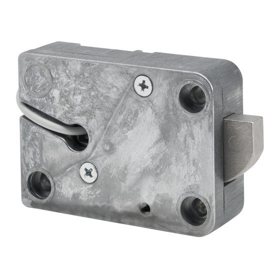
Digital Platform Alarm Cable for Duress/Remote Enable/Remote Disable/External Power
Sargent & Greenleaf, Inc.
One Security Drive
Nicholasville, KY 40356 USA
Phone: (800)-826-7652
Fax: (800)-634-4843
Copyright
2017, Sargent & Greenleaf, Inc.
©
ex: 36* 00123456# 1# 3# 3#
ex: 36* 00123456# 1# 4# 4#
White Cable
Brown Cable
Yellow Cable
Green Cable
Red Cable
Black Cable
Orange Cable
Blue Cable
Max Current: 2A
ex: 38* 00123456# 2# 2#
ex: 37* 00123456# 1# 1# 1#
Common
Input 0-5 Volt
Open Drain output (200 milliamp continuous current)
10 kOHM pullup to sys Power
Power (-)
Power (+) 9- 12 volts DC/ 2 amps
* - UL Rated 9 - 12VDC 2A Rated Supply
Future Features
Sargent & Greenleaf S.A.
1024 Ecublens, Switzerland
Phone: +41-21 694 34 00
9, Chemin du Croset
Fax: +41-21 694 34 09
Document 630-935
Revised 08/24/2018
Advertisement
Table of Contents

Summary of Contents for Sargent and Greenleaf 3028
- Page 1 Operating Instructions Model 3006, 3007, 3028, 3029 GENERAL NOTES • Orange and Blue wires are used to hook up external power. • Red and Black wires are used to setup the duress signal • Yellow and Green wires will be used to setup remote enable/disable signal. • The audit features, peripheral devices and accessories, software features, one-time code functionality, USB functionality, wireless functionality, remote functionality, and other additional features are beyond the scope of the UL 2058 standard and not part of the UL Listing. • External Power Supply Requirements: Use only UL Listed / Recognized Category APHV / EPBU / QQGQ / QQGQ7 external power supply meeting the following specifications. Connectors and wires connecting power supply to lock must be UL Listed / Recognized. Voltage: 9 – 12 VDC Max Current: 2A Operation Enable The Duress Alarm Feature 38* Programmer PIN Code# Option # Option # ex: 38* 00123456# 2# 2# Enabling the Duress alarm will allow the user to send a signal to the alarm system.
- Page 2 Installation 3006 and 3007 Place the lock case on its cover side. Remove the steel plate that covers the lock case by removing the three screws which hold it in place. This will require you to remove the screw under the sticker. When removing the steel plate to make sure the drive cam and white plastic washer stay in place. The area circled in RED is the location where this cable will be installed. Observe the connecter and its orientation. This will be important when plugging the connection into the lock. Line the plug and connector up so that they are in the same orientation. Orientation of the pins on a 3006/3007 Once the connection between the lock and cable is completed, the cable should be routed in the space provided. Once the metal cover is reattached, this routing will avoid the cable from being pinched. The cable should be routed as shown. Using the screws removed in the first step, replace the cover and tighten. 3028 and 3029 When installing the cable into the 3028/3029 lock mechanisms, no cover needs to be removed. Access is available at the circled connection point on the side of the lock. Orientation of the pins on a 3028/3029...


Need help?
Do you have a question about the 3028 and is the answer not in the manual?
Questions and answers