Table of Contents
Advertisement
Quick Links
Advertisement
Table of Contents

Related Manuals for Autoscript ELP 15 PLUS


Summary of Contents for Autoscript ELP 15 PLUS
- Page 1 ELP 15 PLUS On-Camera Prompter Part No. ELP15PLUS-ME www.autoscript.tv...
- Page 2 Copyright © 2014 All rights reserved. Original Instructions: English All rights reserved throughout the world. No part of this document may be stored in a retrieval system, transmitted, copied or reproduced in any way, including, but not limited to, photocopy, photograph, magnetic or other record without the prior agreement and permission in writing of the Vitec Group plc.
-
Page 3: Table Of Contents
Contents Safety..........2 Configuration . -
Page 4: Safety
Intended Use CAUTION! Only use the power cable specified for this The ELP 15 PLUS on-camera prompter has been designed to provide product and certified for the country of use. a high quality teleprompting facility for television broadcasting. CAUTION! Using alternative power sources will invalidate The prompter is intended for use by television camera operators within the system EMC liability. -
Page 5: About This Manual
WARNING! When using this product outside, protect from rain using a suitable waterproof cover. About this Manual This manual describes the installation of the ELP 15 PLUS onto a Ventilation suitable camera support as part of a full prompting system, using the... -
Page 6: Components And Connections
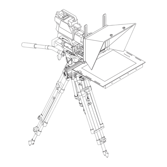
Components and Connections On-Camera Prompter Key Components The illustration below highlights the key components used in a typical prompter installation. Camera mounting plate Counterbalance weights Blackout cloth Hood Reflective glass LED TFT monitor display Monitor mounting brackets Main prompter mounting extrusion Hood mounting brackets... -
Page 7: Prompter Installation Components
Components and Connections Box Contents Prompter Installation Components The following section describes the range of component parts available for a complete prompter installation using the ELP 15 PLUS monitor. Part Description FH-S Folding hood (unassembled) RGFH-S Reflective glass panel EXT-M... -
Page 8: Prompter Monitor Connections
Components and Connections Prompter Monitor Connections Prompter Monitor Control Panel Menu button VGA IN socket Selection button Composite video IN socket Up navigation button Power indicator LED Down navigation button 12 VDC OUT accessory socket Power button 12 VDC IN power socket Power indicator LED... -
Page 9: Tools Required
Installation Mounting the Camera and Extrusion Firmly clip the camera into position on the mounting plate. WARNING! Before attempting to install or adjust the prompter assembly, the tilt axis of the head support must be securely locked horizontally (tilt axis). A camera mounting plate must be fitted between the head support and the camera body to allow installation of the prompter system. - Page 10 Installation Remove the two protective end caps from the extrusion. Centralise the extrusion, aligning the marker with the centre of the camera lens. Turn the rods to tighten the clamps onto the rear of the extrusion. The clamps can be tightened securely by using an Allen key as a Slide the extrusion over the clamps on the end of the rods.
-
Page 11: Mounting The Prompter Monitor
Installation Mounting the Prompter Monitor Align the clamps on the monitor brackets with the slot in the front of the extrusion and slide the assembly into position. WARNING! Before attempting to install or adjust the prompter monitor assembly, the tilt axis of the head support must remain securely locked horizontally. -
Page 12: Assembling And Fitting The Hood
Installation Assembling and Fitting the Hood Centralise the monitor on the extrusion and tighten the two fixing screws. The standard folding hood (FH-S) is recommended for use with the ELP15 PLUS on camera prompter. Fixing brackets are supplied for use with the hood. - Page 13 Installation Fitting the Extrusion End Caps Repeat steps 1 and 2 for the opposite hood bracket. WARNING! Risk of personal injury or injury to others. When the hood has been installed, the supplied extrusion end caps must be fitted. Firmly press the extrusion end caps into place at both ends of the extrusion.
-
Page 14: Adjusting The Prompter Assembly Position
Installation Adjusting the Prompter Assembly Position Adjust the vertical position of the hood on the slides to centralise it with the camera lens and fully re-tighten the clamping knobs. The horizontal position of the prompter assembly must be adjusted to optimise its position relative to the camera lens. -
Page 15: Fitting The Reflective Glass Panel
Panel Orientation For the ELP 15 PLUS prompter to display images, it is essential that the reflective side of the glass is installed facing outwards. The reflective Carefully position the glass panel on the bottom glazing bar inside side of the glass can be established as follows: the hood. -
Page 16: Fitting The Light Shield Cloth
Installation With the glass supported at all times, replace the top glazing bar Fitting the Light Shield Cloth and secure with the screw fixings. CAUTION! Ensure that the light shield cloth is only loosely fitted around the body of the servo lens to allow it to continue operating freely. -
Page 17: Fitting The Counterbalance Weights
Installation Fitting the Counterbalance Weights Balancing and Adjustments The prompter installation must have counterbalance weights fitted to WARNING! After fitting or adjusting the prompter assembly the rear of the mounting to compensate for the front-heavy effect of the and any accessories, the payload must be correctly re- prompter monitor and hood. - Page 18 Installation If the payload is not correctly balanced, lock the tilt axis and: Additional Adjustments a) If the payload is falling forward (front heavy), move the WARNING! Before attempting to adjust the prompter counterbalance weights further back on the rods. assembly, the tilt axis of the head support must be securely b) If the payload is falling backwards (rear heavy), move the locked horizontally (tilt axis).
-
Page 19: Connecting The Prompter Monitor
Accessory DC Connection The connections panel is located at the rear of the monitor. CAUTION! The accessory DC out socket is intended for use with approved Autoscript accessories only. Do not Video Connection exceed the current output limit of the product when Connection using composite video or HD/SDI to the powering auxiliary devices. -
Page 20: Powering Up
Installation Powering Up Before powering up, ensure that all external cable connections have been secured correctly. To power up, depress the on/off power switch. If power is present, the power indication LED will illuminate. -
Page 21: Configuration
Configuration Control Panel Buttons Monitor Function OSD Menus The buttons on the control panel are used to configure and operate the A description of the monitor function OSD setup menus is shown in the prompter monitor screen. following table, with main pages, sub menus and any parameters that can be changed by the user. - Page 22 Configuration Sub Menu Parameters Description Sub Menu Parameters Description 3D NR • Standard Selects the desired NR mode Main Page - FUNCTION • Strong Sleep Timer 0 - 240 Min Adjusts the sleep time duration • Auto • Off Zoom Mode •...
-
Page 23: Maintenance
Maintenance Routine Maintenance No solvents or glass cleaners should be used. Only use clean water and a damp lens cloth when cleaning. Do not apply excessive pressure The ELP15 PLUS on-camera prompter requires minimal routine to the reflective glass panel during the cleaning process. maintenance, apart from checking the connections and overall operation periodically. -
Page 24: Troubleshooting
Troubleshooting Fault Check Comments The monitor is not Check that the DC power source is connected and secured. See the section Power Connection on powering up. page 17 Check that AC power is being supplied to the DC adaptor. No prompting text Check that the video cable is connected and the video source is active. -
Page 25: Technical Specification
Technical Specification Physical Data Connections Data Width*........415 mm (16.3 in) Composite Video In and Out Height* . -
Page 26: General Notices
General Notices FCC Certification Declaration of Conformity ELP15 Plus Prompter ELP15PLUS-ME Vitec Videocom Limited declares that this product has been FCC Notice manufactured in accordance with BS EN ISO 9001:2008. This product complies with the limits for a Class A digital device, This product complies with the following EU Directives: pursuant to Part 15 of the FCC Rules. - Page 27 General Notices European Union Waste of Electrical and Electronic Equipment (WEEE) Directive (2002/96/EC) This symbol marked on the product or its packaging indicates that this product must not be disposed of with general household waste. In some countries or European Community regions separate collection systems have been set up to handle the recycling of electrical and electronic waste products.
- Page 32 Publication part No. ELP15PLUS-4980/1 Autoscript www.autoscript.tv itec Group brand...
Need help?
Do you have a question about the ELP 15 PLUS and is the answer not in the manual?
Questions and answers