
Related Manuals for E.T. Systems DC BLUE ADVANCED


Summary of Contents for E.T. Systems DC BLUE ADVANCED
- Page 1 ET DC BLUE ADVANCED INSTALLER 2012.025.12.05.2014 Domestic garage door operator Installer Instructions www.et.co.za...
- Page 2 ET DC BLUE ADVANCED INSTALLER 2012.025.12.05.2014 TABLE OF CONTENTS Page Category Introduction Safety obligations and general warnings. Technical specifications. Component identification and descriptions. Hardware installation Installing the clutch release mechanism on the sledge/traveller. Sectional overhead door – Installing the wall mount bracket.
- Page 3 ET DC BLUE ADVANCED INSTALLER 2012.025.12.05.2014 IMPORTANT WARNINGS TO THE INSTALLER AND GENERAL SAFETY OBLIGATIONS Caution! It is important for personal safety to follow all the instructions carefully. Incorrect installation or misuse • may cause serious personal harm. Keep the instructions in a safe place for future reference.
- Page 4 ET DC BLUE ADVANCED INSTALLER 2012.025.12.05.2014 Installation: • Remov e all cables, latches/locks or catches not necessary for automation. Ensure the working area is clear of obstructions and obstacles. Install the door sticker depicting the safety rev erse test and keeping door area clear. This sticker should be fixed to the inside surface of the door or near any permanent door control switches such as a wall console if installed.
- Page 5 ET DC BLUE ADVANCED INSTALLER 2012.025.12.05.2014 COMPONENT IDENTIFICATION AND DESCRIPTIONS Diagram Diagram Description Description number number W all mount bracket Nylock nuts M8 Piv ot pin 8mm x 90mm Flat washers M6 Cotter pins 1.8mm x 35mm Coach screws 8 x 60mm...
- Page 6 ET DC BLUE ADVANCED INSTALLER 2012.025.12.05.2014 HARDWARE INSTALLATION INSTALLING THE MANUAL OVERRIDE CLUTCH ASSEMBLY ONTO THE SLEDGE/TRAVELLER (See page 5 for component identification) The diagrams below show how to install the manual override clutch assembly onto the sledge traveller. Ensure the 4 machine screws are securely fastened. Do this prior to installing the drawbar.
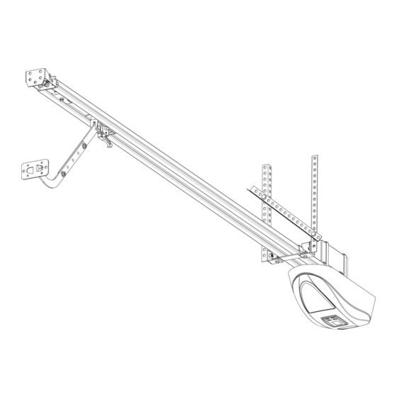
- Page 7 ET DC BLUE ADVANCED INSTALLER 2012.025.12.05.2014 HARDWARE INSTALLATION Standard Single Track or Double Track Sectional Garage Door Method INSTALLING THE WALL MOUNT BRACKET (See page 5 for component identification) The diagram below shows how to determine the mounting height and position of the wall mount bracket, in the case of a standard single track or double track overhead sectional garage door system.
- Page 8 ET DC BLUE ADVANCED INSTALLER 2012.025.12.05.2014 INSTALLING THE DOOR MOUNT BRACKET (See page 5 for component identification) Mount the door mount bracket on the inside fascia of the door as shown below. Keep it as in line as possible with the top guide rollers and centred from side to side of the door.
- Page 9 ET DC BLUE ADVANCED INSTALLER 2012.025.12.05.2014 HARDWARE INSTALLATION Trackless tip-up door INSTALLING THE WALL MOUNT BRACKET (See page 5 for component identification) From the top edge of the door in the closed position, measure 275 – 300mm perpendicular to the top edge of the door.
- Page 10 ET DC BLUE ADVANCED INSTALLER 2012.025.12.05.2014 INSTALLING THE DOOR MOUNT BRACKET (See page 5 for component identification) Mount the door mount bracket on the top edge of the door, where it is centred from side to side of the door.
- Page 11 SUPPLYING HOUSEHOLD POWER TO THE MOTOR-HEAD The DC BLUE ADVANCED © comes supplied with an IEC and SANS compliant 220Vac power cord, 1,5m in length. Plug the sealed non-serviceable 3 pin 15Amp plug into a certified 15Amp plug socket that is installed outside of the workings of the garage door system, yet still within reach of the power cord.
- Page 12 ET DC BLUE ADVANCED INSTALLER 2012.025.12.05.2014 OPTIONAL EXTRA DEVICES WIRING CONNECTIONS www.et.co.za...
- Page 13 ET DC BLUE ADVANCED INSTALLER 2012.025.12.05.2014 CONTROL PANEL DASHBOARD AND PROGRAMMING MENU SUMMARY (How to navigate the menu options) NOTE! Before attempting to execute the instructions, read the complete instruction table, for a setup option. Some steps require a response before a safety timeout expires and you may still be reading the next step when the timeout expires.
- Page 14 ET DC BLUE ADVANCED INSTALLER 2012.025.12.05.2014 PROGRAMMING Open and closed limit position setup and door load profiling. From Standby Mode Action Response To enter the program Display begins flashing “P” menu. Press and hold SET and buzzer beeps twice button until buzzer beeps to confirm the main twice.
- Page 15 ET DC BLUE ADVANCED INSTALLER 2012.025.12.05.2014 SETTING THE OBSTRUCTION FORCE SENSING, SAFETY LEVEL. Default level - 3 From Standby Mode Action Response To enter the Program Display begins flashing “P” menu. Press and hold SET and buzzer beeps twice button until buzzer beeps to confirm the main twice.
- Page 16 ET DC BLUE ADVANCED INSTALLER 2012.025.12.05.2014 ACTIVATING SAFETY BEAM MODE. Default – Off (Disabled) NB! When auto-close mode is activated, the safety beam mode automatically becomes active. This is mandatory as auto-close mode may never be used without a set of safety beams installed.
- Page 17 ET DC BLUE ADVANCED INSTALLER 2012.025.12.05.2014 ACTIVATING THE AUTO-CLOSE MODE AND SELECTING AN AUTO-CLOSE TIME. Default – Off NB! When auto-close mode is activated, the safety beam mode automatically becomes active. This is mandatory as auto-close mode may never be used without a set of safety beams installed.
- Page 18 ET DC BLUE ADVANCED INSTALLER 2012.025.12.05.2014 SELECTING A LOCK MODE. Default – Off NB!! The “E-Coms” output on the control card is designated to be used with an “E-Coms” Relay module, when using any electric lock. These modules are only available via ET Systems.
- Page 19 ET DC BLUE ADVANCED INSTALLER 2012.025.12.05.2014 LEARNING A TRANSMITTER CODE IN THE RECEIVER MEMORY. Max users (BT) button trigger channel = 35 user codes Max users (LT) courtesy light trigger channel = 5 user codes NB!! The built in receiver will only work with the ET BLU MIX © enhanced rolling code or ET BLUE rolling code transmitters.
- Page 20 ET DC BLUE ADVANCED INSTALLER 2012.025.12.05.2014 CLEARING A SINGLE TRANSMITTER BUTTON CODE FROM THE RECEIVER MEMORY. This can only be completed if the remote control that must be erased is present. If the remote control that must be removed is missing or unobtainable, then a master erase procedure (Page 21) must be performed and the remaining, valid user codes must all be learnt into the memory once again.
- Page 21 ET DC BLUE ADVANCED INSTALLER 2012.025.12.05.2014 MASTER ERASING ALL TRANSMITTER BUTTON CODES FROM THE MEMORY. From Standby Mode Action Response Display begins flashing To enter the Program “P” and buzzer beeps menu. Press and hold SET twice to confirm the...
- Page 22 ET DC BLUE ADVANCED INSTALLER 2012.025.12.05.2014 A QUICK METHOD OF LEARNING A TRANSMITTER BUTTON CODE INTO THE RECEIVER MEMORY WITHOUT ENTERING THE PROGRAMMING MENU. Max users (BT) button trigger channel = 35 user codes NB!! No remote codes can be learnt into the (LT) courtesy light channel this way.
- Page 23 ET DC BLUE ADVANCED INSTALLER 2012.025.12.05.2014 BASIC OPERATING FEATURES Basic open and close triggers using the (BT) button trigger. Example 1. Simply opening the door fully and closing the door again fully. Action Response Door in the closed position. Courtesy light off.
- Page 24 ET DC BLUE ADVANCED INSTALLER 2012.025.12.05.2014 BASIC OPERATING FEATURES Basic open and close triggers using the (BT) button trigger. Example 2. Using the (BT) button trigger input while the door is running. Action Response Door in the closed position. Courtesy light off.
- Page 25 ET DC BLUE ADVANCED INSTALLER 2012.025.12.05.2014 ADVANCED OPERATING FEATURES Advanced triggers using the remote (BT) button trigger (PARTY MODE) Example 3. Using the remote (BT) button trigger to disable any closing triggers Response Action TO ACTIVATE Door in the closed position.
- Page 26 ET DC BLUE ADVANCED INSTALLER 2012.025.12.05.2014 ADVANCED OPERATING FEATURES Advanced triggers via the remote (BT) button trigger and (LT) courtesy light trigger (HOLIDAY LOCK-OUT MODE) Example 4. Using the remote (BT) button trigger and (LT) courtesy light to lock out any opening triggers...
- Page 27 ET DC BLUE ADVANCED INSTALLER 2012.025.12.05.2014 ADVANCED OPERATING FEATURES LOCK MODES – STRIKE LOCK MODE. NB!! This function is only available if an ET E-Coms relay module is installed. Action Response Door in the closed position. Courtesy light off. Lock relay module off.
- Page 28 ET DC BLUE ADVANCED INSTALLER 2012.025.12.05.2014 ADVANCED OPERATING FEATURES LOCK MODES – MAGNETIC LOCK MODE. NB!! This function is only available if an ET E-Coms relay module is installed. Action Response Door in the closed position. Courtesy light and lock relay module, off.
- Page 29 ET DC BLUE ADVANCED INSTALLER 2012.025.12.05.2014 ADVANCED OPERATING FEATURES Auto-close feature. Response Action Door in the closed position. Courtesy light off. Press and release either Door begins opening the remote button and courtesy light trigger or the hardwired switches on.
- Page 30 ET DC BLUE ADVANCED INSTALLER 2012.025.12.05.2014 ADVANCED FEATURES Courtesy light NB!! In the case of a household mains failure, the courtesy light does not function. The buzzer will also emit a short beep every 15 seconds for 5 minutes after any BT transaction when the household mains power is off.
- Page 31 ET DC BLUE ADVANCED INSTALLER 2012.025.12.05.2014 WARNINGS WHEN USING A (BT) BUTTON TRIGGER FROM STANDBY MODE. Display Buzzer and light Reason Resolve by. Safety beam Page 29 obstructed. Rapid Holiday lock-out Page 26 active. Open/closed limits and load profile routine incorrectly...
- Page 32 • Any unauthorized non-manufacturer modifications to the product or components thereof. • The use of the ET DC BLUE ADVANCED operator in heav y traffic applications such as office parks and residential complexes. • The use of the DC BLUE ADVANCED operator in non-weatherproof applications such as car ports.
Need help?
Do you have a question about the DC BLUE ADVANCED and is the answer not in the manual?
Questions and answers
After loadshesding my roll up door is going up but doesn't god down again. And there is a red light flashing on the box.
How to replace the globe