
Related Manuals for Eaton CEAG ZB-S


Summary of Contents for Eaton CEAG ZB-S
- Page 1 CEAG ZB-S Mounting and Operating Instructions CEAG Central Battery System ZB-S Target group, part 1: Qualified electrician acc. to EN 50110-1 Target group. part 2: Electrical instucted persons...
-
Page 2: Table Of Contents
3.16 Data Sheet for US-S/SOU2 ....22 In no event will Eaton be responsible to the purchaser 3.17 Data Sheet for US-S/SOU1 ....22 or user in contract, in tort (including negligence), strict 3.18... -
Page 3: Contents
Contents 4.4.13 Bus-Technology according to RS 485 PART 2 or CG-S-Bus ......55 4.4.14 Batteries for emergency power supply . -
Page 4: Important Notes
Important Notes Important Notes Keep the instructions near to the system, accessible for every person working with the system and at all times. Read the instructions carefully before working on and with the system! 1 General Information CEAG Notlichtsysteme GmbH can accept no liability and/or give no warranty in respect of any defects that may occur with the supply and intallation of CEAG emergency lighting 1.1 Description of Symbols... -
Page 5: Safety
2 Safety 2 Safety 2.2 Contents of Operating Instructions Every person, ordered to work with the system, has to read the instructions carefully to understand them before The central battery system is designed and built in work begins. This takes also place when the person conformity with the latest technical rules at the time of has already worked with a similar kind of battery or was its development and production, so it is safe to operate. -
Page 6: Responsibility Of The Operator
2 Safety 2.4 Responsibility of the Operator 2.7 Personal Protective Equipment Keep the instructions near to the system, accessible for When working on and with the system it is necessary to every person working with the system and at all times. wear: The System must be in a proper and safe condition when using it. -
Page 7: Technical Data
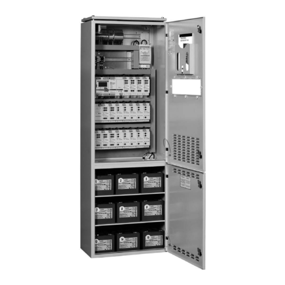
3 Technical Data 3 Technical Data 3.1 Data Sheet for ZB-S/26 interior side view, left front view, open interior side view, right Type of system: ��������������������������������������������ZB-S 26 Construction: ������������������������������������������������Sheet steel cabinet with partial viewing window in the door Height: ����������������������������������������������������������2050 mm Width:�����������������������������������������������������������800 mm Depth: �����������������������������������������������������������400 mm Weight without battery: �������������������������������approx�... -
Page 8: Data Sheet For Zb-S/18
3 Technical Data 3.2 Data Sheet for ZB-S/18 Type of system: ��������������������������������������������ZB-S 18 Construction: ������������������������������������������������Sheet steel cabinet with partial viewing window in the door Height: ����������������������������������������������������������2050 mm interior side view, left front view, open interior side view, right Width:�����������������������������������������������������������800 mm Depth: �����������������������������������������������������������400 mm Weight without battery: �������������������������������approx�... -
Page 9: Data Sheet For Zb-S/Lad
3 Technical Data 3.3 Data Sheet for ZB-S/LAD Type of system: ��������������������������������������������ZB-S LAD (Cable entry from top) Construction: ������������������������������������������������Sheet steel cabinet with a door made of sheet blatt Anlage Height: ����������������������������������������������������������2050 mm Width:�����������������������������������������������������������800 mm Depth: �����������������������������������������������������������400 mm : ZB-S LAD Weight without battery: �������������������������������approx�... -
Page 10: Data Sheet For Zb-S/10C
3 Technical Data 3.4 Data Sheet for ZB-S/10C Type of system: ��������������������������������������������ZB-S 10C Construction: ������������������������������������������������Sheet steel compact cabinet with divided door Height: ���������������������������������������������������������2050 mm Width:�����������������������������������������������������������800 mm Depth: �����������������������������������������������������������400 mm Weight without battery: �������������������������������approx� 155 kg Insulation class: �������������������������������������������I Degree of protection: �����������������������������������IP 20 External painting: �����������������������������������������Structure powder laquer RAL 7035 light grey Cable entry: ��������������������������������������������������at the top (prepunched roof sheeting) Cabinet construction: �����������������������������������one-piece, not divisible... -
Page 11: Data Sheet For Zb-S/10C6
3 Technical Data 3.5 Data Sheet for ZB-S/10C6 Type of system: ��������������������������������������������ZB-S 10C6 Construction: ������������������������������������������������Sheet steel compact cabinet with divided door Height: ����������������������������������������������������������2050 mm Width:�����������������������������������������������������������800 mm Depth: �����������������������������������������������������������600 mm Weight without battery: �������������������������������approx� 205 kg Insulation class: �������������������������������������������I Degree of protection: �����������������������������������IP 20 External painting: �����������������������������������������Structure powder laquer RAL 7035 light grey Cable entry: ��������������������������������������������������at the top (prepunched flange plates) Cabinet construction: �����������������������������������two parts, screwed together, divisible... -
Page 12: Data Sheet For Zb-S/18C6
3 Technical Data 3.6 Data Sheet for ZB-S/18C6 Type of system: ��������������������������������������������ZB-S 18C6 Datenblatt Anlage Construction: ������������������������������������������������Sheet steel compact cabinet with divided door Anlagentyp ZB-S 18C6 40071689062 Height: ����������������������������������������������������������2050 mm : Stahlblech Compactschrank mit geteilter Tuer Bauhoehe : 2050 mm Width:�����������������������������������������������������������800 mm Baubreite : 800 mm... -
Page 13: Data Sheet For Zb-S/26C6
3 Technical Data 3.7 Data Sheet for ZB-S/26C6 Type of system: ��������������������������������������������ZB-S 26C6 Construction: ������������������������������������������������Sheet steel compact cabinet with divided Datenblatt Anlage door Height: ����������������������������������������������������������2250 mm ZB-S 26C6 40071689064 Anlagentyp : Stahlblech Compactschrank mit geteilter Tuer Width:�����������������������������������������������������������800 mm Bauhoehe : 2250 mm Depth: �����������������������������������������������������������600 mm Baubreite : 800 mm... -
Page 14: Data Sheet For Zb-S/18C3
3 Technical Data 3.8 Data Sheet for ZB-S/18C3 Type of system: ��������������������������������������������ZB-S 18C3 Construction: ������������������������������������������������Sheet steel compact cabinet with divided door Height: ����������������������������������������������������������1800 mm Width:�����������������������������������������������������������600 mm Depth: �����������������������������������������������������������350 mm Weight without battery: �������������������������������approx� 120 kg Insulation class: �������������������������������������������I Degree of protection: �����������������������������������IP 20 External painting: �����������������������������������������Structure powder laquer RAL 7035 light grey Cable entry: ��������������������������������������������������at the top (prepunched roof sheeting) Cabinet construction: �����������������������������������one-piece, not divisible... -
Page 15: Data Sheet For Zb-S/10C3
3 Technical Data 3.9 Data Sheet for ZB-S/10C3 Type of system: ��������������������������������������������ZB-S 10C3 Construction: ������������������������������������������������Sheet steel cabinet with partial viewing window in the door Height: ����������������������������������������������������������1800 mm Width:�����������������������������������������������������������600 mm Depth: �����������������������������������������������������������350 mm Weight without battery: �������������������������������approx� 115 kg Insulation class: �������������������������������������������I Degree of protection: �����������������������������������IP 20 External painting: �����������������������������������������Structure powder laquer RAL 7035 light grey Cable entry: ��������������������������������������������������at the top (prepunched roof sheeting) -
Page 16: Data Sheet For Zb-S/2C3
3 Technical Data 3.10 Data Sheet for ZB-S/2C3 Type of system: ��������������������������������������������ZB-S 2C3 Construction: ������������������������������������������������Sheet steel cabinet with sheet steel door Height: ����������������������������������������������������������1000 mm Width:�����������������������������������������������������������600 mm Depth: �����������������������������������������������������������300 mm Weight without battery: �������������������������������approx� 50 kg Insulation class: �������������������������������������������I Degree of protection: �����������������������������������IP 20 External painting: �����������������������������������������Structure powder laquer RAL 7035 light grey Cable entry: ��������������������������������������������������at the top (prepunched roof sheeting) Cabinet construction: �����������������������������������one-piece, not divisible... -
Page 17: Data Sheet For Us-S/36
3 Technical Data 3.11 Data Sheet for US-S/36 Type of system: ��������������������������������������������US-S/36 Construction: ������������������������������������������������Sheet steel cabinet with partial viewing window in the door Height: ����������������������������������������������������������2050 mm Width:�����������������������������������������������������������800 mm Depth: �����������������������������������������������������������400 mm Weight without battery: �������������������������������approx� 170 kg Insulation class: �������������������������������������������I Degree of protection: �����������������������������������IP 20 External painting: �����������������������������������������Structure powder laquer RAL 7035 light grey... -
Page 18: Data Sheet For Us-S/28
3 Technical Data 3.12 Data Sheet for US-S/28 Type of system: ��������������������������������������������US-S/28 Construction: ������������������������������������������������Sheet steel cabinet with partial viewing window in the door Height: ����������������������������������������������������������2050 mm Width:�����������������������������������������������������������800 mm Depth: �����������������������������������������������������������400 mm Weight without battery: �������������������������������approx� 165 kg Insulation class: �������������������������������������������I Degree of protection: �����������������������������������IP 20 External painting: �����������������������������������������Structure powder laquer RAL 7035 light grey... -
Page 19: Data Sheet For Us-S/21
3 Technical Data 3.13 Data Sheet for US-S/21 Type of system: ��������������������������������������������US-S/21 Construction: ������������������������������������������������Sheet steel wall mounting cabinet with a door made of sheet Height: ����������������������������������������������������������1200 mm Width:�����������������������������������������������������������600 mm Depth: �����������������������������������������������������������300 mm Weight without battery: �������������������������������approx� 110 kg Insulation class: �������������������������������������������I Degree of protection: �����������������������������������IP 54 External painting: �����������������������������������������Structure powder laquer RAL 7035 light grey... -
Page 20: Data Sheet For Us-S/13
3 Technical Data 3.14 Data Sheet for US-S/13 Type of system: ��������������������������������������������US-S/13 Construction: ������������������������������������������������Sheet steel wall mounting cabinet with a door made of sheet Height: ����������������������������������������������������������800 mm Width:�����������������������������������������������������������600 mm Depth: �����������������������������������������������������������250 mm Weight without battery: �������������������������������approx� 75 kg Insulation class: �������������������������������������������I Degree of protection: �����������������������������������IP 54 External painting: �����������������������������������������Structure powder laquer RAL 7035 light grey... -
Page 21: Data Sheet For Us-S/5
3 Technical Data 3.15 Data Sheet for US-S/5 Type of system: ��������������������������������������������US-S/5 Construction: ������������������������������������������������Sheet steel wall mounting cabinet with a door made of sheet Height: ����������������������������������������������������������600 mm Width:�����������������������������������������������������������400 mm Depth: �����������������������������������������������������������250 mm Weight without battery: �������������������������������approx� 42 kg Insulation class: �������������������������������������������I Degree of protection: �����������������������������������IP 54 External painting: �����������������������������������������Structure powder laquer RAL 7035 light grey... -
Page 22: Data Sheet For Us-S/Sou2
3 Technical Data 3.16 Data Sheet for US-S/SOU2 Type of system: ��������������������������������������������US-S/SOU2 Construction: ������������������������������������������������Surface-mounted plastic distributor housing of thermoplastic with transparent viewing door Height: ����������������������������������������������������������458 mm Width:�����������������������������������������������������������295 mm Depth: �����������������������������������������������������������129 mm Weight : ��������������������������������������������������������approx� 8,8 kg Insulation class: �������������������������������������������Il Degree of protection: �����������������������������������IP 65 Colour : ���������������������������������������������������������Grey (RAL 7032) Cable entry : �������������������������������������������������from above (with integral elastic sealing membranes for cable infeed, with cable... -
Page 23: Data Sheet For Esf-E30/13S
3 Technical Data 3.18 Data Sheet for ESF-E30/13-S Type of system: ��������������������������������������������ESF-E30/13S Construction: ������������������������������������������������Sheet steel wall mounting cabinet with a door made of sheet incl� cross point closing and a double-bit key cylinder Permission: ���������������������������������������������������ABZ Z-86�2-1 Height: ����������������������������������������������������������1150 mm Width:�����������������������������������������������������������885 mm Depth: �����������������������������������������������������������405 mm Weight without battery: �������������������������������approx�... - Page 24 3 Technical Data 3.19 Data Sheet for US-S ESF30 13-P Type of system: ��������������������������������������������US-S ESF30 13-P Construction: ������������������������������������������������Wall-mounted cabinet Permission:: ��������������������������������������������������ABZ Z-86�1-46 Height: ����������������������������������������������������������1278 mm Width:�����������������������������������������������������������918 mm Depth: �����������������������������������������������������������496 mm Weight without battery: �������������������������������approx� 205 kg Insulation class: �������������������������������������������I Degree of protection: �����������������������������������IP 42 External painting: �����������������������������������������Structure powder laquer RAL 7035 light grey Cable entry: ��������������������������������������������������at the top (cable bundle entry) Hinge: ����������������������������������������������������������������right...
-
Page 25: Data Sheet For Esf-E30/28-S
3 Technical Data 3.20 Data Sheet for ESF-E30/28-S Type of system: ��������������������������������������������ESF-E30/28S Construction: ������������������������������������������������Sheet steel wall mounting cabinet with a door made of sheet incl� cross point closing and a double-bit key cylinder Permission:: ��������������������������������������������������ABZ Z-86�2-1 Height: ����������������������������������������������������������2190 mm Width:�����������������������������������������������������������885 mm Depth: �����������������������������������������������������������405 mm Weight without battery: �������������������������������approx�... -
Page 26: Data Sheet For Esf-E30/28S-P
3 Technical Data 3.21 Data Sheet for ESF-E30 28-P Type of system: ��������������������������������������������US-S ESF-E30 28-P Construction: ������������������������������������������������Wall-mounted cabinet Permission:: ��������������������������������������������������ABZ Z-86�1-46 Height: ����������������������������������������������������������2053 mm Width:�����������������������������������������������������������918 mm Depth: �����������������������������������������������������������604 mm Weight without battery: �������������������������������approx� 420 kg Insulation class: �������������������������������������������I Degree of protection: �����������������������������������IP 42 External painting: �����������������������������������������Structure powder laquer RAL 7035 light grey Cable entry: ��������������������������������������������������at the top (cable bundle entry) Hinge: ����������������������������������������������������������������right... -
Page 27: Data Sheet For Sou5
3 Technical Data 3.22 Data Sheet for US-S ESF30 SOU5 Anlagentyp � � � � � � � � � � � � � � � � � � � � US-S ESF30 SOU5 Bauart � � � � � � � � � � � � � � � � � � � � � � � Faserplatten Wandschrank Kleinverteiler Bauhöhe/ Baubreite/ Bautiefe �... -
Page 28: Construction And Function
4 Construction and Function 4 Construction and Function 4.1 Example of Control Cabinet-Construction (ZB-S/26) einführung von oben Cable infeed from above Installationsklemme Triple deck tension spring installation terminal with alleitertrennklemme neutral wire Charge module Lademodul CM 1,7 A ( disconnect terminal CM 1.7 A (max. -
Page 29: Product Description
4 Construction and Function 4.2 Product Description ZB-S/LAD These are designed as charging and monitoring units The Central Battery System ZB-S with the new START for the mains and battery supply to a large number of technology is a logical successor to the wellproven substations US-S. -
Page 30: Overview Over The Components
4 Construction and Function 4.4 Overview over the Components Operation Directly on the device 4.4.1 Control Module ZB-S CU CG-S controller using The terminal blocks on the module simplify assembly sealed keypad and and dismantling; the connections are taken out to a 3-tier- installation-terminal with tension spring-connection. - Page 31 4 Construction and Function a usual personal computer (PC) and CEAG-software for the system ZB-S. Communication and control Data exchange with installed CG-S components and CG-S-compatible ballasts (using the cables of the final circuits) RS485 bus allows data to be exchanged with external modules (DLS/3PH-bus-modules or TLS-bus-modules, (RS485 port on the control module, up to 25 devices).
- Page 32 4 Construction and Function as presetting can be called up at any time. 2 relays with common potential, 1 x open contact each with fixed assignment. Contact 44 switches an external buzzer on. Contact 54 is for control of a technical switching cabinet ventilation if required.
-
Page 33: Dc/Dc Converter.2
4 Construction and Function 4.4.2 DC/DC Converter.2 This unit provides the central battery system with 24V and 6V direct voltage. Supply only for optional AC-module. Attention: When using at least two DC-DC converter please observe that all DC-DC converter has to be used side by side on the same module assembly frame. -
Page 34: Baterie Control Modul Bcm
4 Construction and Function 4.4.3 Baterie Control Modul BCM The Charge Control Bus (terminals CCB +, CCB -) controls and monitors the charging boosters CM 1.7 A and CM 3.4 A. Indicators Terminals + - BST ON LED 2.5 A boosters are controlled via the terminals. The LED lights up when the Terminals + - 24V BCM is in operation. - Page 35 4 Construction and Function 4.4.5 Circuit change-over modules overview (SKUs) SKU CG-S 4x1,5A SKU CG-S 2x3A Input Input Nominal voltage AC Nominal voltage AC 220-240 V 220-240 V Nominal voltage DC Nominal voltage DC 184-275 V 184-275 V Rated frequency 50/60 Hz Rated frequency 50/60 Hz...
- Page 36 4 Construction and Function SKU CG 1x6A SOU CG-S 2x4A Input Input Nominal voltage AC Nominal voltage AC 220-240 V 220-240 V Nominal voltage DC 184-275 V Nominal voltage DC 184-275 V Rated frequency 50/60 Hz Rated frequency 50/60 Hz Outputs Outputs Nominal current...
- Page 37 4 Construction and Function SKU CG-S 4x1,5A ATTENTION! Fuses Only fuses approved by CEAG Notlichtsysteme GmbH are permit- On the front panel of the change-over module there are ted to use. per circuit 2 output fuses 2,5 AT / 250 V. The nominal current should not exceed 3 A per circuit! Fuse dimensions: 6.3 mm x 32 mm, sand filled.
- Page 38 4 Construction and Function SKU CG-S 2x3A ATTENTION! Fuses Only fuses approved by CEAG Notlichtsysteme GmbH are permit- On the front panel of the change-over module there are ted to use. per circuit 3 output fuses 5 AT / 250 V. The nominal current should not exceed 3 A per circuit! Fuse dimensions: 6.3 mm x 32 mm, sand filled.
- Page 39 4 Construction and Function SKU CG-S 1x6A ATTENTION! Fuses Only fuses approved by CEAG Notlichtsysteme GmbH are permitted to On the front panel of the change-over module there are use. 3 output fuses 10 AT / 250 V. The nominal current should not exceed 6 A! Fuse dimensions: 6.3 mm x 32 mm, sand filled.
- Page 40 4 Construction and Function SOU CG-S 2x4 A ATTENTION! Fuses Only fuses approved by CEAG Notlichtsysteme GmbH are permit- On the front panel of the change-over module there are ted to use. 2 output fuses 8 AT / 250 V. The nominal current should not exceed 4 A! Fuse dimensions: 6,3 mm x 32 mm, sand filled.
- Page 41 4 Construction and Function Mounting and Operating Instructions CEAG Central Battery System ZB-S 40071860179 (L) November 2018 www.ceag.de...
-
Page 42: Inverter Swr 150
4 Construction and Function 4.4.6 Inverter SWR 150 When the Service Pin is operated the module status is shown as a plain-language readout on the display of the CU CG-S control module. Repeated operation of the SWR´s Sinus-inverter Service Pin takes the operator through the following menu structure of the CU CG-S control module. - Page 43 4 Construction and Function The inverter SWR 150 gets supplied by two voltage Furthermore the currents have to be measured and saved sources, during mains operation from mains and during as written in „5.5 Learn currents“ . An error is detected mains failure from the battery.
- Page 44 4 Construction and Function Maintained light via external power mains supply Switched maintained light via maintained light switch monitoring In this supply mode the safety lighting is supplied by an external phase in mains. This switching mode is used In this switchting mode one light switch of the general particularly for reinstallations with one electric meter lighting is scanned and assigned to the SWR 150 via per circuit.
- Page 45 4 Construction and Function Switched maintained light via external DLS-bus-module In this switching mode one light switch of the general lighting is scanned and assigned to the SWR 150 via programming. An advantage is the free assignment of the light switches to the final circuit.
-
Page 46: Determination Of Current Consumption
4 Construction and Function 4.4.6.1 Determination of current consumption value from the battery Table 1. Battery current consumption values (A) dependent upon number of luminaires and luminous flux ratio (LV%) at 20 °C ambient temperature at the luminaire. International description Socket Lamp power (W) 8W-VVG... - Page 47 4 Construction and Function Table 3. Battery current consumption values (A) dependent upon number of luminaires and luminous flux ratio (LV%) at 20 °C ambient temperature at the luminaire. International description TC-L Socket 2G11 Lamp power (W) Luminous flux ratio (%) Switch setting Number of luminaires / Current consumption from the...
-
Page 48: Event Printer Pd3
4 Construction and Function NOTE NOTE: CEAG Notlichtsysteme GmbH attend on downawards Prior to this, the event printer must be logged out from compatibility at the development and further development the cabinet over the controller CU CG-S! of the modules for one system family (in this case SKU This happens over the menu «Setup printer»... -
Page 49: Relay Module Cg Iv And Cg V
4 Construction and Function 4.4.8 Relay module CG IV and CG V Function of relay contacts CG IV 11/12 21/22 31/32 41/42 51/52 Deep-discharge protection ------ ------ ------ ------ Emergency lighting failure ------ ------ ------ ------ Charging fault ------ ------ ------ ------ Battery operation... -
Page 50: F3 Remote Indication
4 Construction and Function 4.4.9 F3 remote indication Connection of a remote switch Connections are made as per figure (single-line diagram) as well as field installation diagrams and drawings. The CEAG F3 remote switch is powered via the 24-V voltage supply system of CEAG sytems. ATTENTION! Do not use an external 24-V voltage supply! NOTE:... -
Page 51: External Tls-Bus-Module
4 Construction and Function 4.4.10 External TLS-bus-module This module monitors the switching status of buttons for up to two separate stairwell illuminations and transmitts the particular switching status via a RS-485-busline to the controller of the system ZB-S. In mains and emergency operation the circuits of stairlight and emergency light will be operated according to the settings for the controller CU CG-S! In addition to this, a supply of the switcher glow lamps of the connected... - Page 52 3 phase monitoring. The RS 485 interface as well as If the safety system is at the start of the bus cable, then the 24 V DC power supply are supplied from the EATON- the appropriate terminating resistor is to be fitted to safety lighting system.
- Page 53 Technical Data Addressing Prior to operation in a EATON safety lighting system, 3-PM-IO the module address must be set. For this purpose the required address (1 - 25) is to be set on the code switches RS485-BUS on the module front panel using a suitable screwdriver (arrow to number, Figure 2).
- Page 54 Technical Data 4.4.12 CEAG 3-PM Module with 4.4.13 Completing Assembly 24V current loop Refer to the plans and drawings for installation on site The connection in the ZB-S (US-S) control cabinet is and check all of the circuits that have been made. made at the 3-tier terminal block (S3 and S4) for external Check that all connections are tight.
- Page 55 Technical Data Mounting and Operating Instructions CEAG Central Battery System ZB-S 40071860179 (L) November 2018 www.ceag.de...
-
Page 56: Webmodule
Technical data 4.4.14 Webmodule Conform to: EN 60950-1. Developed, manufactured and tested acc. to ISO 9001. Electrical connection Technical data Network Service connection RJ45 Supply voltage 24 V DC Power consumption Status/ Current consumption 33 mA +/- 25% Failure LED Connection RJ45 Insulation class... -
Page 57: Bus-Technology According To Rs
Technical data 4.4.15 Bus-Technology according to RS 485 CG-S-Bus or CG-S-Bus An RS485 bus is used for data communication with external bus modules (3-PM-IO Module or TLS). A connection to a BMS can be done with the CG-S bus. The conductors of the RS485 bus line must be connected to the connection points RS485 A, RS485 B, +24V OUT and -24V OUT of the ZB-S connection terminals. -
Page 58: Batteries For Emergency Power Supply
Technical data 4.4.16 Batteries for emergency ATTENTION! power supply If the mains supply to the ZB-S central battery system is CEAG offers battery cabinet in different dimensions interrupted for more than three days, then the battery cir- and mountings. In this case low-maintenance batteries cuits must be isolated (by removing the battery fuse). -
Page 59: Label Of Zb-S
Technical data 4.5 Label of ZB-S Find the label of the system inside the door. The following technical data is given on the label of the The following technical data is given on the label of the system: battery: Mounting and Operating Instructions CEAG Central Battery System ZB-S 40071860179 (L) November 2018 www.ceag.de... -
Page 60: Example Of Installation
Technical data 4.6 Example of Installation LNLNLNLNLNLNLNLNPEPE *=3PH DLS/3PH-BUS-Modul address 9 8 7 RS485 X X X +++- - - SEA BSEA B XB1 B2 S1S2 S3 S4 C014 12 24223432 C1 44 54 11 12 21 31 32 + - U1 01 U202 U1 01 U202 U1 01 U202... - Page 61 Technical data T1 T1XK1 K1X K2K2 T2T2 X NN PEPE max.10A max.10A address TLS-BUS-Modul T1 K1 K2 T2 9 8 7 RS485 X X X +++- - - SEA BSEA B XB1 B2 Electrical Souce Mains Electrical Souce Mains for Safety Source for Safety Source F1-U F2-U...
-
Page 62: Transport, Packaging And Storage
5 Transport, Packaging and Storage 5 Transport, Packaging and Storage Batteries For battery handling and storage please follow the battery manufacturer´s directions and the instructions about the battery cabinets. 5.1 Safety Notes WARNING! RISK OF INJURY! 5.2 Transport inspection Check delivery on receipt for completeness and for There is a risk of injury when transporting or loading transport damages, immediately. -
Page 63: Installation
6 Installation 6 Installation You must also comply with all standards and directives of the country in which the system is installed and operated. Secure all the cable entry and exit openings in the control 6.1 Safety Notes cabinet with the supplied M-type glands or rubber grom- mets to prevent damage to the cables and ingress of WARNING! RISK OF INJURY! moisture. -
Page 64: Connection To Mains
6 Installation 6.3 Installation Isolate all connecting cables (mains and battery power supply) and lock them out (e. g. by removing all fuses and proper securing of the mains supply distribution board and the battery bank using warning signage and/ or locks). -
Page 65: Usage Of Rcds In The Incoming Mains
6 Installation 6.4.1.1 Usage of RCDs in the incoming Connect the L conductors to the terminals on the outgoing feeder (pos. 2) mains of ZB-S systems Using RCDs in the mains lead to protect against indirect The mains supply is connected in the control cabinet of contact acc. -
Page 66: Connection To Battery Power Supply
6 Installation ZB-S/26 and ZB-S/18 WARNING! The battery power supply is a nominal 216V DC! Improper handling can lead to life-threatening shocks or burns (arcing)! Ensure that the battery banks are connected with the correct polarity. Turn off all connected loads first («Disable system») to prevent arcing when the battery circuit is disconnected (or connection)! NOTE... -
Page 67: Connection Of Temperature Sensor
6 Installation ZB-S/26 and ZB-S/18 X1.1 ZB-S LAD Location of the terminal block for connecting a temperature sensor in a ZB-S control cabinet (1) ATTENTION! For the connection of external temperature sensor an Location of the load disconnector (1) for the battery insulated cable must be used. - Page 68 6 Installation Subrack 1 (with modules fitted) and subrack 2 (with 8 free slots) Pos. 1: plugin terminal block with the module connections (fitted) Pos. 2: lower fixing (pivoted locking pin) for the SKU module Pos. 3: plugin terminal block with the module connections (removed) Pos.
-
Page 69: Commissioning And Other Work
7 Commissioning and other work 7 Commissioning and other work Use only measuring devices which are able to meet the demands of DIN VDE 0413. Disconnect the connecting cables for the mains and 7.1 Safety Notes battery supply. Link the connections L and N of the switch cabinet WARNING! RISK OF INJURY! at the terminals of the mains supply or outgoing distributors. -
Page 70: Checking / Replacing Of Fuses
When central battery systems are supplied without čččččččččččččččččččč battery or the type of battery is unknown the tripple CEAG ZB-S Name charge-voltage is set up with the factory default of 245V (means 2.27V/Z). According to the type of battery the tripple charge-voltage must be fitted at face. -
Page 71: Checking And Replacing Internal Modules
8 Operating 7.7 Checking and replacing external mod- ules For mounting and dismounting of a module please see chapter 6.8 „Connection and installation of external modules“ . Please observce the following: Set the intended address for the module with modules with address switch. -
Page 72: Operating
8 Operating NOTE 8 Operating The following descriptions are not covered by this manual as this requires detailed instructions within the technical 8.1 Safety Notes documentation for these systems: Operating and monitoring the system with an F3 WARNING! RISK OF INJURY! module, CG controller or building management system (BMS) Improper mounting and installation can cause serious... -
Page 73: Control Module Cu Cg-S
8 Operating 8.3.1 Control module CU CG-S 8.3.4 SKU´s of the final circuits The operation of the control module is described in detail The circuit change over module supplies and monitors in the following pages. emergency luminaires with electronic ballasts for DC operation. -
Page 74: Operating The Cu Cg-S Control Module
8 Operating 8.4 Operating the CU CG-S control module Graphic display (main screen during normal operation) LEDs (1) in the top row indicate running functions that were initiated with theFunction buttons (2) Starting point: Main screen aside. The 3 left-hand buttons <Menu>... - Page 75 8 Operating Mounting and Operating Instructions CEAG Central Battery System ZB-S 40071860179 (L) November 2018 www.ceag.de...
- Page 76 8 Operating Operation is the same for ZB-S Main menu Test & status menu systems and for their US-S substations. If password protection is activated, then only the main screen and the Start functiontest Test & status menu main menu options “1 Test and Status Menu”...
- Page 77 8 Operating 3.14 Luminaire setup Block, Reset Webserver setup 3.15 Timer setup Add / remove Block device 3.16 Substation setup Luminaire search Release device 3.17 Connection to BMS Text assignments Manual reset 3.18 Function keys DLS/TLS-Assignment Reset deep discharge 3.19 Optional inputs Memory card Reset ISO-failure...
-
Page 78: Menu 1: "Test & Status Menu
8 Operating 8.4.1 Menu 1: “Test & Status Menu” A battery test run (5 min.) is performed after Overview: <ok> Start functiontest a short mains operation (5 min.). Menu 1.1: Request in view of the of station Start durationtest Main menu The main screen displays a fault message Cancel durationtest... - Page 79 8 Operating <ok> Overview: Select input field/line with Start functiontest SKU 2/1 circuit:1 Menu 1.6: Start durationtest Select SKU or circuit with ..5..10..15..2 Main menu Cancel durationtest Line 3 shows the current settings of —-————————- Test &...
-
Page 80: Menu 2: "Block & Reset Alarms
8 Operating 8.4.2 Menu 2: “Block & reset alarms” <ok> initiates the function: <ok> Overview: This device Block device Release device Menu 2.1: All functions are cancelled; all devices Main menu Manual reset all outputs will be isolated! Device address Reset deep discharge Test &... -
Page 81: Menu 3: "Basic Settings
8 Operating 8.4.3 Menu 3: “Basic settings” Overview: Use the keys to toggle between Language <ok> The currently selected Date & time Main menu “Language: National language” Menu 3.1: language is displayed Functiontest and “Language: english” Test & status menu Durationtest Block &... - Page 82 8 Operating Language Select the input position for date, <ok> B-Test Date&Time Date & time time and interval (in months) with Menu 3.4: We 11.12.07 12:00 Functiontest Change with Durationtest Duration test end Finish with <Menu> etc..
- Page 83 8 Operating Overview: Date & time Setting the time (1 ... 99 minutes) which <ok> Delay time on mains Functiontest Main menu the emergency light remains on after mains Menu 3.5: return in Durationtest supply is restored. Test & status menu minutes Delay time mains return Block &...
- Page 84 8 Operating Overview: Select the system or fault messages which Buzzer assignment Manual reset <ok> activate the buzzer in the switch cabinet. Selective EmgcyOper. Main menu Mains operation Menu 3.9: Relay setup A standard setting according to DIN VDE Mains failure Test &...
- Page 85 8 Operating Overview: Is not printer existing or filed via the <ok> Printer setup Buzzer setup Service-Button the following appears: Menu 3.12: Main menu installed/not installed Display setup Charger setup activated/not activated Printer setup Test & status menu Printer setup Block &...
- Page 86 8 Operating Overview: This menu is used to activate and inter- <ok> Device address: Webserver setup face the system with a master monitor- Menu 3.17: Main menu LON switch no Timer setup ing device using the CG-S bus or the M3 NID00 05 94 75 52 00 Test &...
- Page 87 8 Operating Line selection (1 - 3) with Type: ZB-S Overview: <ok> Connection to BMS Selection of the nominal operating Function keys Nom. op. duration 3h Menu 3.20: Main menu Optional inputs duration (1, 2, 3 or 8h) and limit oper- Limit op.
-
Page 88: Menu 4: "Dls/Tls Setup
8 Operating 8.4.4 Menu 4: “DLS/TLS setup” Overview: <ok>: The search result is accepted; the Menu 4.1: Search DLS/TLS ... Find address: Text assignment parameters will be used by the CU CG-S f <ok> Search result Main menu TLS times the controller Test &... -
Page 89: Menu 5: "Circuit Setup
8 Operating 8.4.5 Menu 5: “Circuit setup” Menu 5.1: Successive selection of the installed Overview: Deactivate SKU Deactivate module <ok> SKUs with Search ext. modules Subrack:N SKU:N Main menu Text assignment Numbering is consecutive; the number Type: SKU CG-S 2x3 Test &... - Page 90 8 Operating Overview: Menu 5.3: Select line 2 or 4 or the input fields in Text assignments Deactivate module <ok> line 2 with Search ext. modules Main menu SKU1/8 circuit:2 Text assignment Successive selection of subrack/SKU Type: SKU CG-S 2x3 Test &...
- Page 91 8 Operating Select line 1, 2, 3 or the input fields in Overview: Menu 5.5: SKU1/8 circuit:2 Deactivate module line 1 with <ok> per luminaire setup Search ext. modules Main menu Text assignment Successive selection of SKU and (final) Maintained light (Batt) Test &...
-
Page 92: Menu 6 "Luminaire Setup
8 Operating 8.4.6 Menu 6 “Luminaire setup” Select line 1 or the input fields in line Overview: <ok> SKU 1/8 circuit:2 Add / remove 1 with Menu 6.1: Luminaire search ...5...10...15...20 Main menu Text assignments Successive selection of SKU/subrack -—————————- Test &... - Page 93 8 Operating Overview: Select the input fields in line 1 with Add / remove <ok> SKU 1/8 circuit:2 Luminaire search Select input field with Main menu Menu 6.4: Text assignments The displays and input options depend Test &...
-
Page 94: Menu 7 "Logbooksetup
8 Operating 8.4.7 Menu 7 “Logbooksetup” <ok> Select the log book entries with Overview: 11.05.12 12:30:00 Search logbook Menu 7 .1: – Line 1: displays date and time for the Erase logbook Event Main menu Save configuration displayed event Line 3 Test &... -
Page 95: Failures
9 Failures 9 Failures As a basic rule: Stop device with the main switch when failures occur which can cause damage to persons, to property and/or to operational safety. Additionally disconnect device from power supply and protect against resetting. NOTE: After troubleshooting power up the system as described in chapter 7 .8. -
Page 96: Bcm Failure Codes
9 Failures 9.1.4 BCM failure codes Failure code request (Z571.0) Please push the Service-Pin for a few seconds. The failures running throw by flashing from the LED “Loadfailure” . Example: 3 x flash, short break, 5x flash O Error code 3 and 5. The request-mode ends automatically when all error codes are shown. -
Page 97: Maintenance / Checking
10 Maintenance / Checking 10 Maintenance / Checking 10.1 Safety Notes WARNING! RISK OF INJURY! Our customer service locations can be found all over Germany, see the enclosed map „Addresses: CEAG Improper maintenance work can cause serious per- Customer Service“ . sonal injury and / or material damage . -
Page 98: Enabling Of End Circuits With Maintenance Work
10 Maintenance / Checking 10.3 Enabling of end circuits with maintenance work Block the system via the control unit (figure). (menu item 8.4.2) <ok> initiates the function: <ok> Overview: This device Block device Release device Menu 2.1: All functions are cancelled; all devices Main menu Manual reset... -
Page 99: Appendix A: Overview Of Terminal
Appendix A: Overview of terminal assignments Appendix A: Overview of terminal assignments All external connections are made at the tension spring terminal blocks at the top of the switch cabinet. The terminal assignment is shown on the schedules on the front of the enclosures (for the screw push-on terminals on the module) and on the terminal blocks for the external connections. - Page 100 Appendix A: Overview of terminal assignments Station type: ZB-S: US-S: Terminal number Type of cable Destination Terminal number Type of cable Destination Mounting and Operating Instructions CEAG Central Battery System ZB-S 40071860179 (L) November 2018 www.ceag.de...
-
Page 101: And Buzzers
Appendix B: VDE requirements for telecommunication contacts and buzzers Appendix B: VDE requirements for telecommunication contacts and buzzers ZB-S default setting Notes / Comments Relay 1 Relay 2 Relay 3 Relay 4 Relay 5 Designation Buzzer C0/14/12 C0/24/22 C0/34/32 C1/44 C1/54 Mains operation means: ZB-S not Mains operation... - Page 102 Appendix B: VDE requirements for telecommunication contacts and buzzers NOTE: Comply with the national regulations and guidelines for indicating and signalling when using a remote switch or remote indicator for emergency lighting systems. Contact assignment: C0/14: NO C0/24: NO C0/34: NO C1/44: NO C0/12: NC C0/22: NC...
-
Page 103: For The Luminaires
Appendix C: Location plan for the luminaires Appendix C: Location plan for the luminaires Date: ______________________ Decice address: ________________________________________________ Time: ______________________ Name of the system: ________________________________________________ Luminaire Luminaire Switch 1 Switch 1 Switch 2 Switch 2 Luminaire Luminaire Switch 1 Switch 1 Switch 2 Switch 2... -
Page 104: Appendix D: Installation Example
Appendix D: Installation example monitoring modules Appendix D: Installation example monitoring modules V-CG-S 4 – 400 W V-CG-SE 4 – 400 W Monitoring Module Monitoring Module with Control Input UV-A positive logic inverted logic V-CG-SB Monitoring module V-CG-SUW Monitoring module with DALI control input with change over unit Switch-/dimming unit... -
Page 105: Appendix E: Customer Service Order
Appendix E: Customer Service Order Appendix E: Customer Service Order Fax/E-Mail to: CEAG, central customer service Fax No. +49 (0)2921 69-624, Email: kundendienst@ceag.de Customer Service Order From: _________________________________________ Request No.: __________________________________ We hereby request the CEAG Customer Service to carry out the work indicated below: Customer: _______________________________________________________________________________________ Street: __________________________________________________________________________________________ Postcode /Town: _________________________________________________________________________________... - Page 106 General Safety instructions - batteries General Safety instructions - batteries English – General safety instructions stanju. • Izbjegavajte stvaranje elektrostatičkog napona i • The batteries are not suitable for private use. izboja/iskri. Rizik od eksplozije. • An installation must be performed by qualified •...
- Page 107 General Safety instructions - batteries General Safety instructions - batteries Pусский tarkoitukseen asianmukaisessa ja vahingoittumat- tomassa kunnossa. Общие инструкции по безопасности • Vältä sähkövarauksen kertymistä ja purkautumista/ • Аккумуляторы не предназначены для бытово- kipinöitä. Räjähdysvaara. го использования. kuris gali nudeginti. •...
- Page 108 General Safety instructions - devices General Safety instructions - devices Deutsch English Hrvatski Allgemeine Sicherheitshinweise General safety instructions Opće sigurnosne upute • Die Geräte sind nicht für den privaten Gebrauch • The devices are not suitable for private use. • Uređaji nisu prikladni za privatnu upotrebu. geeignet.
- Page 109 General Safety instructions - devices General Safety instructions - devices • Fjern alle fremmedlegemer fra enhetene før rezervă, tensiunea de reglare și curenții de Lietuviškas Suomalainen første gangs bruk. scurgere.) Nu întrerupeți circuitele sub sarcină. Bendrieji saugos nurodymai Yleiset turvallisuusohjeet •...
- Page 110 Notes Notes Mounting and Operating Instructions CEAG Central Battery System ZB-S 40071860179 (L) November 2018 www.ceag.de...
- Page 111 Notes Notes Mounting and Operating Instructions CEAG Central Battery System ZB-S 40071860179 (L) November 2018 www.ceag.de...
- Page 112 At Eaton, we’re energized by the challenge of powering a world that demands more. With over 100 years experience in electrical power management, we have the expertise to see beyond today. From groundbreaking products to turnkey design and engineering services, critical industries around the globe count on Eaton.
Need help?
Do you have a question about the CEAG ZB-S and is the answer not in the manual?
Questions and answers