Table of Contents
Advertisement
Quick Links
For replacement parts visit
WENPRODUCTS.COM
Your new tool has been engineered and manufactured to WEN's highest standards for dependability, ease
of operation, and operator safety. When properly cared for, this product will supply you years of rugged,
trouble-free performance. Pay close attention to the rules for safe operation, warnings, and cautions. If
you use your tool properly and for its intended purpose, you will enjoy years of safe, reliable service.
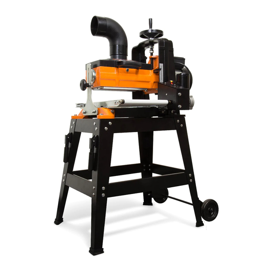
DRUM SANDER
IMPORTANT:
NEED HELP? CONTACT US!
Have product questions? Need technical support?
Please feel free to contact us at:
800-232-1195
techsupport@wenproducts.com
WENPRODUCTS.COM
MODEL 65911
10 - INCH
(M-F 8am-5pm CST)
Advertisement
Table of Contents

Related Manuals for Wen 65911


Summary of Contents for Wen 65911
- Page 1 WENPRODUCTS.COM IMPORTANT: Your new tool has been engineered and manufactured to WEN’s highest standards for dependability, ease of operation, and operator safety. When properly cared for, this product will supply you years of rugged, trouble-free performance. Pay close attention to the rules for safe operation, warnings, and cautions. If you use your tool properly and for its intended purpose, you will enjoy years of safe, reliable service.
-
Page 2: Table Of Contents
28-3/8" x 23-1/4" x 47-1/4" Weight 161 lbs NOTE: Your drum sander is compatible with the WEN 28200 10 ft. dust hose and the WEN 28221 20 ft. dust hose, available at wenproducts.com. Sandpaper may be purchased from wenproducts.com by searching 65910. -
Page 3: Introduction
INTRODUCTION Thanks for purchasing the WEN drum sander. We know you are excited to put your tool to work, but first, please take a moment to read through the manual. Safe operation of this tool requires that you read and understand this operator’s manual and all the labels affixed to the tool. This manual provides information regarding potential safety concerns, as well as helpful assembly and operating instructions for your tool. -
Page 4: General Safety Rules
GENERAL SAFETY RULES Safety is a combination of common sense, staying alert, and knowing how your item works. SAVE THESE SAFETY INSTRUCTIONS. WARNING: Read and understand all warnings, cautions and operating instructions before using this tool. Failure to follow all instructions listed below may result in personal injury and tool damage. - Page 5 GENERAL SAFETY RULES WARNING: Dust generated from certain materials can be hazardous to your health. Always operate the tool in a well-ventilated area and wear a dust mask. Use dust collection systems when processing wood and plastics. Dust extractors or dust bags must not be connected when processing metals.
-
Page 6: Electrical Information
ELECTRICAL INFORMATION GROUNDING INSTRUCTIONS IN THE EVENT OF A MALFUNCTION OR BREAKDOWN, grounding provides the path of least resistance for an electric current and reduces the risk of electric shock. This tool is equipped with an electric cord that has an equipment grounding conductor and a grounding plug. -
Page 7: Specific Rules For Your Drum Sander
SPECIFIC RULES FOR DRUM SANDERS 1. INSPECT THE TOOL. Before operation, check the tool for any damage or missing parts. Make sure all adjustments are correct and all connections are tight. Do not use the tool if any part is missing or damaged. Check the conveyor belt to make sure there is no debris or sawdust between components. -
Page 8: Know Your Drum Sander
KNOW YOUR DRUM SANDER Use the diagram below to become familiarized with the components and controls of your drum sander. If you have any questions or concerns, please contact our Customer Service at (800) 232-1195, M-F 8-5 CST or email us at techsupport@wenproducts.com. Height Adjustment Wheel Circuit Breaker Dust Collection Port... -
Page 9: Unpacking
UNPACKING PACKING LIST Check your packing list against the diagram below. If any part is damaged or missing, please contact our customer service at (800) 232-1195, M-F 8-5 CST or email us at techsupport@wenproducts.com. PARTS QTY. HARDWARE QTY. Drum Sander Assembly Carriage Bolts M8-1.25 x 12 Short Top Brace 14-5/8”... -
Page 10: Assembly
ASSEMBLY WARNING: To avoid injury from accidental startups, do not plug in the drum sander until all assembly and preparation procedures have been completed. ASSEMBLING THE STAND (FIG. 2) Long Top Braces (x2) Short Top Braces (x2) Long Bottom Braces (x2) Short Bottom Braces (x2) Legs (x4) M8-1.25x12 Carriage Bolts (x32) - Page 11 ASSEMBLY INSTALLING THE WHEELS (FIG.3) Wheel Brackets (x2) Wheel Axle (x1) M8-1.25 Lock Nuts (x4) Wheels (x2) M8-1.25x16 Hex Bolts (x4) Cotter Pins 4x20mm (x2) 1. Attach the 2 wheel brackets to the 2 wheel-mounting legs with (4) M8-1.25 x 16 hex bolts and (4) M8-1.25 lock nuts.
- Page 12 ASSEMBLY MOUNTING THE MACHINE ONTO THE STAND (FIG. 5) M10-1.5 x 30 10mm Flat Hex Bolts (x4) Washers (x4) Drum Sander M10-1.5 x 30 Assembly (x1) Hex Nut (x4) 1. This sander weighs over 150 lbs, so you will need a strong muscular friend (or a trustworthy foe) to help you lift it up.
- Page 13 3. Connect the dust hose to your dust-collection system of choice. Fig. 7 NOTE: The dust port on your sander is compatible with the WEN 28200 10 ft. dust hose and the WEN 28221 20 ft. dust hose, available at wenproducts.com.
-
Page 14: Sandpaper Installation
You can also purchase a 3-1/4 inch (82mm) wide sandpaper roll and trim it using the diagram below or your existing sandpaper as a template. NOTE: Your friends at WEN offer pre-cut sandpaper in different grit sizes specifically for your drum sander. Sandpaper can be ordered from wenproducts.com by searching the model number 65910. - Page 15 SANDPAPER INSTALLATION WARNING: To avoid injury from accidental startups, always ensure that the tool is switched OFF and unplugged from the power supply before making adjustments. REMOVING EXISTING SANDPAPER (FIG. 8 & 9) 1. Disconnect the drum sander from the power supply. 2.
-
Page 16: Preparation
PREPARATION INSTALLING NEW SANDPAPER (FIG. 10-13) 1. Roll the sanding drum until the slot on the left of the drum is on top. Reach under the left lip of the drum to locate the spring clamp. NOTE: Align the directional arrows printed on the bottom of sandpaper with the drum’s rotation direction. - Page 17 PREPARATION PLANNING YOUR WORK Planning your work before operation will help to save time and minimize setups. Group your workpiece by thickness and grit requirements. Work through each required sanding grit from the thickest to the thinnest material. Then, change to a finer grit sandpaper and work through the process again.
- Page 18 PREPARATION MINOR WARPING. When sanding workpieces with minor warping, Convex make sure the concave side is downward, facing the conveyor belt. Check that the workpiece can be stable and well supported. Do not place the workpiece with the convex side down, as it will Concave wobble during operation and cause kickback and possible injury.
- Page 19 PREPARATION ADJUSTING THE FEED RATE (FIG. 15) The feed rate is the speed that the conveyor belt travels to deliver the workpiece through the sanding drum. Setting the feed rate too fast may overload the motor, while setting the feed rate too slow may burn the surface of the workpiece.
- Page 20 PREPARATION 1. Make sure the drum sander is switched off and disconnected from the power supply. Connect the sander to a suitable dust collection system before operation. 2. Inspect the workpiece and make sure it is acceptable for the sanding operation. Make sure that the correct sandpaper grit is selected and the sandpaper is properly installed onto the drum.
-
Page 21: Adjustments
ADJUSTMENTS WARNING: To avoid injury from accidental startups, always ensure that the tool is switched OFF and unplugged from the power supply before making adjustments. The following settings should be correctly adjusted from the factory. However, they may need to be checked and adjusted to ensure optimal sanding performance. - Page 22 ADJUSTMENTS CONVEYOR BELT TRACKING ADJUSTMENT The conveyor belt should track in the center of the conveyor table. Occasionally check the belt tracking by running the conveyor belt at high speed for a few minutes. If the belt shifts to one side or the other, the belt tracking needs to be adjusted.
- Page 23 ADJUSTMENTS BELT TO DRUM ALIGNMENT (FIG. 19 & 20) To achieve an even sanding result, the sanding drum and Sanding Drum conveyor belt should be parallel with each other. To check the belt to table alignment: Parallel 1. Make sure the height adjustment tension screws are Conveyor Belt properly adjusted.
- Page 24 ADJUSTMENTS 1. Turn off and disconnect the machine from the power source. 2. Remove the screw and washer securing the drum cover and lift the cover open. 3. There are two screws (Fig. 22 - 1) on both ends of the drum. To increase the roller pressure, evenly tighten all four Phillips screws by rotating them clockwise in small increments.
-
Page 25: Maintenance
MAINTENANCE WARNING: To prevent serious injury from accidental operation, always turn off and disconnect the machine from power source before installation, cleaning and maintenance operations. WARNING: Use caution when performing maintenance on the drum sander. Do not wear long sleeve shirts, neckties or jewelry. Make sure to tie back long hair. DAILY INSPECTION For optimum performance, inspect the machine before every use. - Page 26 MAINTENANCE 4. Turn on the machine. Hold the long abrasive belt cleaning stick with two hands and gently lower the stick onto the rotating sanding drum. Move the cleaning stick from side to side to remove the clogging sawdust from the drum 5.
- Page 27 MAINTENANCE CONVEYOR FEED BELT REPLACEMENT (FIG. 25 & 26) Regularly check the conveyor belt before operation. The conveyor belt may need replacement due to normal wear and tear, contact with the sanding drum abrasive during operation, mis-tracking of the conveyor belt, or excessive build-up. Follow the steps below to remove and replace the conveyor belt. 1.
-
Page 28: Troubleshooting Guide
TROUBLESHOOTING WARNING: Stop using the tool immediately if any of the following problems occur. Repairs and replacements should only be performed by an authorized technician. For any questions, please contact our customer service at (800) 232-1195, M-F 8-5 CST or email us at techsupport@wenproducts.com. - Page 29 TROUBLESHOOTING ASSEMBLY & ADJUSTMENTS COMMON CAUSE PROBLEM SOLUTION 1. Conveyor belt dirty or worn. Workpiece slips on 1. Clean/replace conveyor belt (page 22). 2. Pressure rollers not properly conveyor. 2. Properly adjust pressure roller (page 23). adjusted. 1. Height lock knob not tight and 1.
-
Page 30: Exploded View & Parts List
STAND PART NO. DESCRIPTION QTY. PART NO. DESCRIPTION QTY. Handle Grip 65910-017 Lock Nut M8-1.25 Handle 65911-018 Left Rear Stand Leg Phlp Hd Screw Carriage Bolt 65910-019 M4-0.7 x 35 M8-1.25 x 12 65911-001 (Handle) Handle Bracket Left Wheel 65910-020... - Page 31 EXPLODED VIEW & PARTS LIST CONVEYOR PART NO. DESCRIPTION QTY. PART NO. DESCRIPTION QTY. 65910-101 Conveyor Belt 65910-131 Switch Housing Bracket 65910-102 Cap Screw M5-0.8 x 16 65910-132 Terminal Block 4P 65910-103 Compression Spring 65910-133 Switch Housing Plate Transformer Omron Outfeed Adjustable Roller 65910-134 65910-104...
- Page 32 EXPLODED VIEW & PARTS LIST MAIN...
- Page 33 Part No. Description Qty. Part No. Description Qty. 65910-250 Flat Washer 12mm 65910-201 Clutch Damper 65910-202 Hex Bolt M8-1.25 x 30 65910-251 Elevation Rotation Label 65910-203 Dust Hood 65910-252 Handwheel Assembly 65910-204 Dust Connector 90 Deg 4” 65910-253 Elevation Leadscrew 65910-205 Lock Nut M8-1.25 65910-254...
-
Page 34: Warranty Statement
(2) years from date of purchase or 500 hours of use; whichever comes first. Ninety days for all WEN products if the tool is used for pro- fessional or commercial use. - Page 35 NOTES...
- Page 36 THANKS FOR REMEMBERING...
Need help?
Do you have a question about the 65911 and is the answer not in the manual?
Questions and answers