
Related Manuals for Regulus TRS6 K


Summary of Contents for Regulus TRS6 K
- Page 1 Installation and Operation Manual REGULUS TRS6 K CONTROLLER TRS6 K...
-
Page 2: Table Of Contents
Contents Contents .................. 2 Settings ................. 22 5. Settings ..................... 22 Safety Instructions ..............4 5.1. Settings heating circuit (Heating circ.) ......22 A.1 EG Declaration of Conformity ..........4 5.2. Settings heating circuit 2 (Heating circ. 2)....26 A.2 General Information ..............4 5.3. - Page 3 This Manual applies to the following hardware versions: TRS6 K TRS6 K 3 output mechanical relays 230VAC 2 PWM/0-10V outputs for high-efficiency pumps 6 inputs for Pt1000 temperature sensors...
-
Page 4: Safety Instructions
Safety Instructions A.1 EG Declaration of Conformity By affixing the CE mark to the unit the manufacturer declares that the TRS6 K Controller conforms to the following relevant safety regulations: EC low voltage directive 2014/35/EC • EC electromagnetic compatibility directive 2014/30/EC •... -
Page 5: Warranty
A.5 Warranty The Controller has been manufactured and tested with regard to high quality and safety requirements. The Controller is subject to the statutory guarantee period of two years from the date of sale. The warranty and liability shall not include, however, any injury to persons or material damage that is attributable to one or more of the following causes: Failure to observe these installation and operating instructions •... -
Page 6: Description Of The Controller
IP rating IP40 Overvoltage category Overvoltage category Pollution degree TRS6 K Mechanical relay 460 VA (AC1), 460 W (AC3) 3 (R1, R2, R3) 0-10V output, 10% tolerance, 10 kΩ, or PWM output, 1kHz, 10V 2 (V1, V2) Pt1000 sensors, range from -40 °C to 300 °C... -
Page 7: Controller Description
B.3 Controller Description TRS6 K Controller permits control of up to 2 heating circuits (one mixed, one unmixed), control of DHW heating and control of automatic operation of solar thermal systems, solid-fuel boilers and auxiliary electric / gas-fired heat sources. It involves two PWM outputs for high-efficiency pump control, 3 relay outputs and 6 inputs for temperature sensors. -
Page 8: Installation
Installation C.1 Wall Installation Install the Controller in dry rooms only! Unscrew cover screw completely. Carefully pull upper part of housing from lower part. Set upper part of housing aside. Do not touch the electronics inside. Hold the lower part of the housing up to the selected position and mark the three mounting holes. -
Page 9: Installing The Temperature Sensors
On the control board CAN1 CAN bus connection (1=high,2=low) CAN2 CAN bus connection (1=high,2=low) VFS1 Not used in Regulus systems. VFS2 Terminal: Connection: Terminal: Connection: GND bridge for sensors, V1 and V2 outputs, power supply neutral conductor N network outer conductor L... -
Page 10: Hydraulic Variants
D.2 Hydraulic Variants The following illustrations should be regarded only as schematic representations of the respective hydraulic systems and do not claim to be complete. Under no circumstances should the controller replace any safety devices. Depending on the specific application, additional system and safety components such as check valves, non-return valves, safety temperature limiters, scalding protectors, etc., may be required. - Page 11 DHW 2. Combination thermal store (HSK) with a solid fuel boiler and a mixed heating circuit room temperature For RegulusBIO MIX TRS6 K pump station thermal store temperature hot water storage tank temperature solid fuel boiler output temperature...
- Page 12 - closing auxiliary heat source in thermal store 5. Thermal store with a solid fuel boiler and a mixed heating circuit room temperature For RegulusBIO MIX TRS6 K pump station thermal store temperature solid fuel boiler output temperature heating water temperature...
- Page 13 7. Thermal store with a solid fuel boiler, a mixed heating circuit and heat exchange to HW storage tank room temperature For RegulusBIO MIX TRS6 K pump station thermal store temperature HW storage tank bottom section temperature (heat exchange) solid fuel boiler output temperature...
- Page 14 11. Pump station controlling a solid-fuel boiler pump, a heating circuit and heat exchange to HW storage tank (afterheating in HW storage tank) hot water storage tank temperature For RegulusBIO MIX TRS6 K pump station solid fuel boiler output temperature HW storage tank bottom section temperature (heat exchange)
- Page 15 13. Mixed heating circuit room temperature heating water temperature outdoor temperature PWM signal for heating circuit circulation pump heating circuit mixing valve - opening heating circuit mixing valve - closing power switching for heating circuit circulation pump 14. Mixed heating circuit and unmixed heating circuit room temperature (heating circuit 1) room temperature (heating circuit 2) heating water temperature, circuit 2...
-
Page 16: Operation
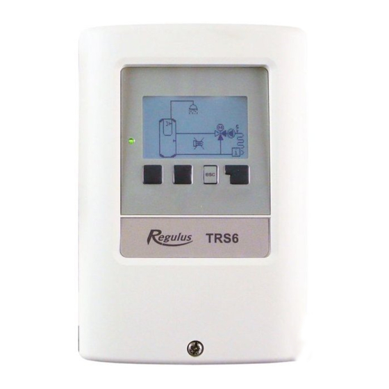
Operation E.1 Display and Input The display (1) shows in text and graphical mode the hydraulic variant, desired and measured values and other text information. The LED (2): is lit green – when a relay is switched on is lit red - when Auto mode is set and all relays are off flashes slowly red –... -
Page 17: Free Commissioning
E.3 Free Commissioning If you decide not to use the commissioning help, you should do the necessary settings in the following sequence: menu 10. Language • menu 3.1. Time and Date • menu 7.1. Program Selection • menu 5. Settings, all values. •... -
Page 18: Measurement Values
Measurement Values 1. Measurement Values Menu 1. Measurement Values is intended to display the current measured temperatures. The selected program and the specific model design determine which measurement values are displayed. The menu is closed by pressing “esc” or selecting “Exit measurements”. If “error”... -
Page 19: Statistics
Statistics 2. Statistics Menu 2. Statistics is intended for function control and long-term monitoring of the system. The menu is closed by pressing “esc” or selecting “Exit statistics”. For system data statistics it is essential for the time to be set accurately on the controller. -
Page 20: Periods
Periods 3. Periods Menu 3. Periods contains settings for time, date and operating times for the heating circuit. The menu is closed by pressing “esc” or selecting “Exit periods”. The associated temperature reference values are specified in Menu 5. Settings. 3.1. -
Page 21: Operating Mode
Operating Mode 4. Operating Mode Menu 4. Operating Mode can be used to switch the controller to automatic mode, turn it off, or switch to manual mode. The menu is closed by pressing “esc” or selecting “Exit operating mode”. 4.1. Manual In Manual mode, the individual relay outputs and the connected consumers can be checked for proper functioning and correct assignment. -
Page 22: Settings
Settings 5. Settings In Menu 5. Settings the system parameters are set. The menu is closed by pressing “esc” or selecting “Exit settings”. By no means does the controller replace any safety elements in a heating circuit, DHW circuit, solar circuit and in electric devices of a heating system. - Page 23 5.1.5. Heating curve The weather compensating curve is used to control the heat dissipation of the heating circuit relative to the outdoor temperature. The curve can be set either as simple, or as split that is divided by a slope change point into two parts. The simple curve can be set using one parameter.
- Page 24 In this manner it is possible to carry out e.g. quick heating up after night operating hours through a steeper heating water temperature rise, or on the contrary, a quicker temperature drop during a faster transition to night operating hours. 5.1.9.
- Page 25 5.1.17. Thermal inertia of a building Thermal inertia of a building indicates how fast the calculated desired heating water temperature (following the heating curve) is influenced by a change in outdoor temperature. The heavier the building design, the more slowly can be the heating water temperature modified through the outdoor temperature.
-
Page 26: Settings Heating Circuit 2 (Heating Circ. 2)
5.1.21. PV contact 1 This sensor input could be used as a PV-contact of Photovoltaic-System. If the PV-Contact set in this menu is closed, the heating circuit is set to Daytime mode. For info on the operation and wiring of the PV contact please consult the technical manual of your PV system. 5.1.22. -
Page 27: Day Reference Value (14 Day Ref. Val.)
5.3.6. Buffer DHW load The DHW heating from the thermal store is turned on at an active heat request for DHW and if the temperature at the thermal store sensor is at least 8°C higher than at the DHW sensor. The DHW heating from the thermal store is shut down if the temperature difference between the thermal store and HW storage tank is less than 4 °C or if the temperature at the DHW sensor has reached the desired value and no DHW heat request is present. -
Page 28: Heat Transfer
5.5.5. Tmax DF-Drain Max. temperature at the heat consumer sensor for switching off the differential thermostat function. If the temperature at the consumer sensor is higher than DF-Drain, the differential thermostat output contacts will not close. 5.6. Heat transfer The menu is available only if the heat transfer function is assigned to an output in menu 7. Special functions. The function of heat transfer between two hot water storage tanks that will switch on the output if the switch-on temperature difference between sensors 5.6.4. -
Page 29: Solid Fuel Boiler
5.8.3. TH Set Preset temperature to switch on an aux. heat source. The heat source will switch on when the temperature at the reference sensor (depending on the active request) drops below this value. In case of an active request, the reference sensor is the DHW sensor (5.3.8), in case of an active request for thermal store charging, the reference sensor is the thermal store (buffer) sensor (5.1.16.). -
Page 30: Solar
5.12.4. Starting aid This function is not used for Regulus solar collectors. For some solar thermal systems, in particular for evacuated tube collectors, the measurement recording on the collector sensors may be too slow or imprecise, because the sensor is often not on the warmest spot. -
Page 31: Gas Boiler (Burner)
“Frost Level 2”, the controller will turn on the pump without disruption. If the collector temperature exceeds the value “Frost level 2” by 2 °C, the pump will turn off again. Energy is lost through the collector through this function! Regulus solar thermal system use antifreeze fluid only and the frost protection is off. -
Page 32: Return Flow Increase
5.17.1. DHW request The Boiler function will be activated only when there is an active demand for DHW heating (the measured DHW temperature has dropped below the currently desired value following the set DHW temperatures and periods – see menu 5.3.). 5.17.2. -
Page 33: Circulation (Dhw Recirculation)
5.22.2. RL Tmax A temperature difference between the storage sensor (5.22.4.) and the heating return flow sensor (5.22.3.) to switch on (Δt on) and off (Δt off) the return flow increase function. 5.22.3. Return flow sensor The temperature sensor placed at a heating return flow – a lower temperature is expected than at the storage sensor. 5.22.4. - Page 34 5.24.2. Reference humidity: Max. humidity to switch on the dehumidifier function. The function will be switched on depending on the active operating mode if the actual humidity is higher than the set value. 5.24.3. Hysteresis Hysteresis to switch off the dehumidifier. If the humidity drops below the value set here (5.24.2. Reference humidity) by the dehumidifier hysteresis value, the function will be switched off.
-
Page 35: Protective Functions
Protective Functions 6. Protective Functions In Menu 6. Protections the system protective functions are set and activated. The menu is closed by pressing “esc” or selecting “Exit protections”. By no means does the controller replace the safety appliances on site! 6.1. -
Page 36: Special Functions
Special Functions 7. Special Functions In Menu 7. Special Functions the basic controller settings and expanded functions are set. The menu is closed by pressing “esc” or selecting “Exit Special Functions”. The settings in this menu should only be changed by a specialist. 7.1. -
Page 37: Speed Control V1
7.2.7. Show signal Represents the set pump signal in a graphic and text overview. 7.3. Speed control V1 This menu involves setting the logic for a pump speed control through V1 output. The speed control function permits to change the speed of the connected pumps. This menu may be unavailable in some program versions. -
Page 38: Pump Settings V2
7.3.6. Setpoint This value is the control setpoint for speed control M 3 (see Chap. 7.3.1.) If this value undershot at the collector sensor, the speed is reduced. When it is exceeded, the speed is increased. 7.4. Pump settings V2 This menu involves settings for V2 speed control output. - Page 39 7.7.2.5. Increase If the temperature drops very fast, this value is subtracted from the measured flow temperature so that the mixer’s reaction is stronger. If the measured temperature does not drop any more, the measured value is used again. The measurement occurs once every minute. These settings are only necessary in special cases at the time of initial commissioning by the specialist.
-
Page 40: Relay 2 (Settings For R2 Output)
7.7.17. Dehumidifier Dehumidifier settings are described in Chap. 5.24. 7.7.18. Parallel operation The function switches parallel to the set signal output – both the outputs switch in parallel. The function can be inverted, so the output switches contrary to the set signal output. 7.7.18.2. -
Page 41: Network
7.15. Network If applicable, the network settings of the connected data logger have to be adjusted. Regulus TRS6 K controller does not feature connection to a data logger and the menu 7.15.1-7.15.3 is not needed. 7.15.1. Access Control This menu lets you give up to 4 users access to the data logger. The users that are registered then have access to the controller or respectively the data logger. -
Page 42: Menu Lock
Menu Lock 8. Menu Lock Menu "8. Menu lock” can be used to secure the controller against unintentional changing the set values. The menu is closed by pressing “esc” or selecting “Exit menu lock”. The menu lock represents a feature securing the controller against unintentional changing the set values. The menus listed below remain completely accessible despite the menu lock being activated, and can be used to make adjustments if necessary: 1. -
Page 43: Service Values
Service values 9. Service values The menu “9. Service values” can be used for remote diagnosis by a specialist in the event of an error etc. Enter the values into the table when an error occurs. The menu can be closed by pressing “esc”. 9.1. -
Page 44: Language
Language 10. Language Menu “10. Language” is used to select the language for the menu guidance. This is queried automatically during initial commissioning. -
Page 45: Malfunctions, Additional Info
Malfunctions, Additional Info Z.1. Malfunctions with error messages If the controller detects a malfunction, the red light flashes and the warning symbol also appears in the display. If the error is no longer present, the warning symbol changes to an info symbol and the red light no longer flashes. To obtain more detailed information on the error, press the key under the warning or info (Led fashes + warning symbol. -
Page 46: Replacing The Fuse
Z.2 Replacing the Fuse Repairs and maintenance may only be performed by a specialist. Before working on the unit, switch off the power supply and secure it against being switched on again! Check for the absence of power! Only use the supplied spare fuse or a fuse of the same design with the following specifications: T2A 250V If the mains voltage is switched on and the controller still does not function or display anything, then the internal device fuse may be defective. - Page 48 ©2019 We reserve the right to errors, changes and improvements without prior notice. REGULUS spol. s r.o. E-mail: sales@regulus.eu Web: www.regulus.eu...
Need help?
Do you have a question about the TRS6 K and is the answer not in the manual?
Questions and answers