
Related Manuals for SENSTAR FlexZone


Summary of Contents for SENSTAR FlexZone
- Page 1 ® FlexZone Fence-mounted Locating Perimeter Intrusion Detection Sensor Product Guide G6DA0102-001 Rev L November 14, 2018...
- Page 2 The information provided in this guide has been prepared by Senstar Corporation to the best of its ability. Senstar Corporation is not responsible for any damage or accidents that may occur due to errors or omissions in this guide. Senstar Corporation is not liable for any damages, or incidental consequences, arising from the use of, or the inability to use, the software and equipment described in this guide.
-
Page 3: Table Of Contents
FlexZone sensor cable - - - - - - - - - - - - - - - - - - - - - - - - - - - - - - - - - - - - -... - Page 4 FlexZone sensor cable conditioning - - - - - - - - - - - - - - - - - - - - - - - - - - - - - - - - - - - -...
- Page 5 Installing the FlexZone processor - - - - - - - - - - - - - - - - - - - - - - - - - - - - - - - - - - - 51...
- Page 6 UCM configuration - - - - - - - - - - - - - - - - - - - - - - - - - - - - - - - - - - - - - - - - - - - - - - - -100 Page 6 FlexZone Product Guide...
-
Page 7: System Planning
300 m (984 ft.) long, and will report the alarm status of up to 60 software defined sensor zones. FlexZone will locate the source of a disturbance to within ± 3 m (10 ft.). A single pass of sensor cable can protect a high quality chain-link fence with no middle rail, up to 4.3 m (14 ft.) high. -
Page 8: Security Factors
(pointed stakes or pales). Senstar recommends that the minimum fence height for a FlexZone installation on a flexible fence type is 2.5 m (8 ft.). For rigid fence types the minimum recommended fence height is 2 m (6.5 ft.). -
Page 9: Standard Flexible Fence Types
Rigid fences via the UCM. Begin testing with the Flexible fence setting and use the Rigid fence setting only if adequate detection sensitivity cannot be achieved at the Flexible fence setting. chain-link welded-mesh expanded metal Figure 1: Standard flexible fence types FlexZone Product Guide Page 9... -
Page 10: Rigid Fence Types
Senstar recommends using armored sensor cable on barbed wire. Armored cable is comprised of FlexZone sensor cable inside flexible metal conduit. To protect both the fence and the barbed wire, use armored cable on the barbed wire, and use sensor cable on the fence fabric. Install... -
Page 11: Gates
• when the sensor is active • the type of ground beneath the gate • the overall protection plan (the number of processors and sensor cables, and their location relative to the gate in question) FlexZone Product Guide Page 11... -
Page 12: Buildings, Walls And Other Structures
Connect the cable across the gate using quick-disconnect connectors. Buildings, walls and other structures FlexZone can be used to detect intruders attempting to cut, saw, chisel, drill, or smash their way through building walls, ceilings, roofs, floors, or stock cages. FlexZone sensor cable can be attached to the structure using commercially available fasteners such as cable ties or nail-clamps that ensure good contact between the sensor cable and the protected structure. -
Page 13: Site Survey
Site Survey Site Survey Conduct a site survey to ensure that site conditions are suitable for a FlexZone sensor system. The primary concern is the condition of the fences and gates. Use the results of the site survey to create a site plan. -
Page 14: Perimeter Layout Guidelines
There are two types of FlexZone sensor cable, standard and armored. Both Standard FlexZone sensor cable and Armored FlexZone sensor cable come in 150 m (492 ft.) and 220 m (722 ft.) lengths. Two lengths can be spliced together to provide up to a 300 m (984 ft.) long sensor cable. -
Page 15: Cable Layout Guidelines
FlexZone sensor cable may include a mylar film between the outer black jacket and the braided shield. The mylar film is used in the cable extrusion process and has no effect on the cable’s function. Figure 7: FlexZone sensor cable description Cable layout guidelines •... -
Page 16: Rigid Fences
(Zone 0) in software and will not report sensor alarms. Non-detecting FlexZone cable must be well secured to prevent any cable motion. The length of coaxial cable that is used for lead-in must be deducted from the detecting cable length (maximum cable length detecting plus non-detecting = 300 m, 984 ft.). -
Page 17: Fence Corners And Heavier Gauge Posts (Flexible Fences)
10 m of cable can be coiled and attached to the fence at each side of a cable splice. A 10 m splice loop is comprised of 5 coiled loops of sensor cable with a 60 cm (2 ft.) diameter. Each 60 cm diameter coil of sensor cable contains approximately 2 m of cable. FlexZone Product Guide Page 17... -
Page 18: Gate Bypass
Perimeter layout guidelines Gate bypass If there is a gate within a FlexZone sensor zone, you require a sufficient amount of inactive cable to bypass the gate, even if the gate is protected by sensor cable. Secure the bypass cable and bury it in PVC conduit. -
Page 19: Processor Location Guidelines
Figure 11: Processor location active cable start points The FlexZone processor can be mounted outdoors on a post, either on, or separate from, the fence on which the sensor cables are installed (see Figure 11: ). A rigid fixed post is recommended for outdoor applications. -
Page 20: Power Source And Wiring
Power source and wiring The FlexZone processor can operate on a wide range of input voltages (12 to 48 VDC). The power supply, the number of processors, and the lengths of the power cable runs will determine the gauge of the power cable wiring that is required. -
Page 21: Power Over Ethernet
FlexZone processors from a central control facility. There are two selectable control modes for the FlexZone processor’s inputs and outputs (I/O) local control mode and remote control mode. You set the control mode in software, via the Universal Configuration Module (UCM) which is a Windows-based software application. -
Page 22: Alarm Communication Options
Data over the sensor cables A group of FlexZone processors can communicate via the connected sensor cables. In this case, at least one processor requires a network interface card (NIC) to enable Silver Network communications. -
Page 23: Processor Synchronization
Cable connectors The splice kit is used to join two FlexZone cables together, and to join lead-in cable to sensor cable. The splice kit is also used to make cable repairs. The termination kit is used in situations where a FlexZone sensor cable is not connected to another FlexZone sensor cable. -
Page 24: High Security Installations
High security installations High security installations The FlexZone sensor can provide redundancy for high-security installations, providing certain rules are followed. If these rules are followed, then the system will continue to provide perimeter detection even if one processor fails, or a sensor cable is cut or if one power supply fails. With this configuration, each 300 m of sensor cable is monitored simultaneously, by two processors. -
Page 25: Installation
DO NOT nick or scrape the sensor cable’s outer jacket. • Avoid tight turns in the sensor cable, the minimum bend radius for FlexZone sensor cable is 10 cm (4 in.) and for armored FlexZone cable is 15 cm (6 in.). -
Page 26: Flexzone Sensor Cable Conditioning
Cable conditioning is best done by two people and typically takes about 10 minutes for a 150 m sensor cable. FlexZone cable conditioning can be done by a single person, but it can take significantly longer to complete due to repeatedly walking back and forth. -
Page 27: Cable Conditioning Procedure (Part 2 - Cable Flossing)
(apply no tension) pulling tension to the center conductor first person second person Figure 16: FlexZone cable conditioning (part 2 cable flossing) FlexZone Product Guide Page 27... - Page 28 Figure 17: FlexZone armored cable conditioning (part 2 cable flossing) 2. When the second person observes that the center conductor has been pulled to its limit, the second person waits 10 seconds and then applies light pulling tension to the center conductor...
-
Page 29: Installing Cable On Chain-Link Fences
For a single cable pass, attach the sensor wire to the middle of the fence. • Avoid vertical drops greater than 1 m (3.3 ft.) when installing FlexZone sensor cable. Vertical drops of 1 m or more can result in an area with excessive sensitivity, which may cause nuisance alarms. -
Page 30: Bend Radius
Installing the sensor cable Bend radius • The smallest allowable radius for FlexZone sensor cable is 10 cm (4 in.). • The smallest allowable radius for armored sensor cable is 15 cm (6 in.). 15 cm 10 cm (6 in.) (4 in.) -
Page 31: At Software Defined Zone Boundaries
The loop should measure 30 to 45 cm from top to bottom. Install service loops at fence posts. • For a double cable pass create two equally spaced service loops in the same manner as for a single cable pass. FlexZone Product Guide Page 31... -
Page 32: Drip Loops
This will provide up to 13 m of sensor cable that can be used for future repairs or for changes in the sensor cable layout. Figure 27: illustrates the recommended configuration for a termination loop. Page 32 FlexZone Product Guide... -
Page 33: Splice Loops
Figure 28: illustrates the recommended configuration for splice loops. splice-connection splice point service loops up to 10 m of cable (5 loops, 60 cm diameter) Figure 28: Splice loop example FlexZone Product Guide Page 33... -
Page 34: Installing Cable On Welded-Mesh Fence
1. Dispense the sensor cable alongside the installation location on the secure side of the fence. Do not allow the sensor cable to fall off the spool, as it may twist and kink. (The FlexZone cable should have been deployed at the installation location for the conditioning procedure.) 2. -
Page 35: Double Pass Cable Installation
Installing cable on chain-link fences on page to attach FlexZone sensor cable in a double pass configuration. The cable spacing for a double pass configuration is 1/3 the fence height for the lower pass and 2/3 the fence height for the upper pass. -
Page 36: Installing Cable On Rigid Fences
). Service loops, sensitivity loops and zone demarcation loops are not recommended on rigid fence types. Refer to application note G6DA0309-001 (Using FlexZone on palisade fences) if you are considering installing the FlexZone sensor on a rigid fence type. FlexZone sensor cable ®... -
Page 37: Cable Preparation (All Connections)
4. Peel back and remove the foil covering flush with the black outer jacket. Figure 35: Preparing FlexZone sensor cable steps 3 & 4 5. Trim back the clear tube to a length of 5 mm (1/5 in.) by carefully removing app. 15 mm (3/5 in.) from the end of the cable. -
Page 38: Processor Connections
Installing the sensor cable Figure 36: Preparing FlexZone sensor cable steps 5 & 6 Note For cable splices proceed to Sensor cable splices on page For terminations proceed to Sensor cable terminations on page Processor connections Cable preparation (all connections) on page 37 for steps 1 - 6. -
Page 39: Sensor Cable Splices
DO NOT remove the protective gel inside the enclosure. 13. Snap the enclosure shut ensuring that both tabs are securely locked in the slots. Note The weather-proofing protective gel should be oozing out of the gel snap enclosure. FlexZone Product Guide Page 39... -
Page 40: Sensor Cable Terminations
10. Secure the sensor cable to the termination CCA using the supplied cable ties. Ensure that the heads of the cable ties are both on the same side of the CCA and that they are at a 45º angle from the flat plane of the CCA. Page 40 FlexZone Product Guide... - Page 41 13. Attach the enclosure to the fence. Form a 20 cm (8 in.) drip loop and install the enclosure horizontally to protect the cable entry points from rain and run off. 20 cm (8 in.) Figure 46: Mounting the termination enclosure FlexZone Product Guide Page 41...
-
Page 42: Using The Wireless Gate Sensor To Protect Gates
A gate sensor receiver (GSR) that is mounted on the FlexZone processor receives the transmission and passes on the alarm signal to the FlexZone processor. A rubber whip antenna is mounted on the processor enclosure to facilitate the WGS communications. -
Page 43: Gate Bypass Cable
Gate bypass cable To bypass a gate in a FlexZone zone, run the sensor cable from one side of the gate to the other, underground inside conduit. Secure the bypass cable at both sides of the gate. The bypass cable is then specified as non-detecting during the calibration process (cable set as non-detecting does not report alarms). -
Page 44: Gate Disconnect Assembly
Note The gate disconnect assembly can be used only with sensor cables that are not carrying power and data to other FlexZone processors. Otherwise, using the gate disconnect will interrupt power and data to any processor further down the line. -
Page 45: Installing Armored Flexzone Sensor Cable
(see FlexZone sensor cable conditioning on page 26). FlexZone armored sensor cable (P/N G6FG0200) is comprised of FlexZone sensor cable encased in a flexible, protective 13 mm (1/2 in.) aluminum conduit. • Handle armored cable carefully to prevent twisting, bending, kinking, jerking, or stretching the cable. -
Page 46: Installing Armored Flexzone Sensor Cable
(G6KT0300). Note Senstar strongly recommends the use of a conduit stripping tool to prevent burrs and sharp protrusions at the cut edge of the conduit. Use the supplied bushings to protect the cable at the armor strip point. - Page 47 Fit the protective bushing over the cable and slide it under the armor to protect the sensor cable. Figure 52: Using the supplied bushings to protect FlexZone sensor cable 1. Cut the two sections of armored cable so there is a 10 cm (4 in.) overlap at the location of the splice.
-
Page 48: Armored Cable Terminations
(G6KT0300). Note Senstar strongly recommends the use of a conduit stripping tool to prevent burrs and sharp protrusions at the cut edge of the conduit. Use the supplied bushings to protect the cable at the armor strip point. - Page 49 Fit the protective bushing over the cable and slide it under the armor to protect the sensor cable. Figure 56: Using the supplied bushings to protect FlexZone sensor cable 1. Cut the armored cable 53 cm past the specified location of the cable termination.
-
Page 50: Connecting Armored Sensor Cable To The Processor
6. Prepare the sensor cable for connecting to the processor (see Figure 34: 7. Pass the sensor cable through the cable gland into the enclosure then through the nut. 8. Loosely install the 1/2 in. cable glands. Page 50 FlexZone Product Guide... -
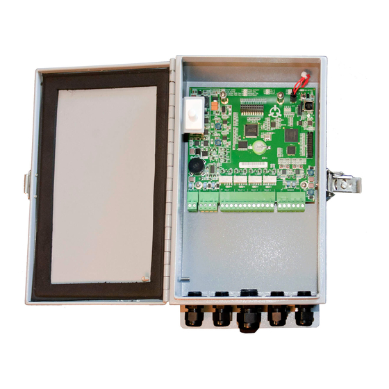
Page 51: Installing The Flexzone Processor
Figure 62: shows a fence- mounted FlexZone processor. Figure 60: illustrates the FlexZone processor features and Table 1 includes feature descriptions. Figure 60: FlexZone processor features FlexZone Product Guide... -
Page 52: Cable Entry Ports
If FlexZone armored cable is being connected to the processor, the two sensor cable ports must be drilled out and fitted with 1/2 in. cable glands (included with armored shell; see... -
Page 53: Free-Standing Or Fence Post Mounting The Enclosure
CAUTION For installations in environments which include hot sunny periods, Senstar recommends that a sun shield be installed to protect the enclosure from direct sunlight, or that the enclosure be installed in a shady area. The maximum operating temperature, as measured inside the enclosure, is 70º... -
Page 54: Surface Mounting
Installing the FlexZone processor 1. Hold the enclosure against the fence at the specified installation location. 2. Feed the end of the gear clamp through an upper flange slot, around the fence post, and back through the second slot. 3. Insert the end of the gear clamp into the gear mechanism and tighten the screw. -
Page 55: Grounding
(do not make ground connections at the other processors). The earth ground connection should be stable and noise free. An improper or unstable earth ground can induce noise in the FlexZone sensor. CAUTION Consult the local electrical code for grounding information. -
Page 56: Processor Wiring Connections
Figure 65: Self-test/Auxiliary device input wiring examples Processor wiring connections You make FlexZone processor wiring connections on removable terminal blocks. The screw terminals accept wire sizes from 12 to 24 AWG, with a 6 mm (¼ in.) strip length. Remove the terminal blocks to make the wiring connections. - Page 57 OPT 3 COM OPT 3 NC OPT 2 NO OPT input 3 OPT 2 COM OPT 2 NC OPT input 4 OPT 1 NO OPT 1 COM OPT 1 NC Figure 67: FlexZone option card wiring diagram FlexZone Product Guide Page 57...
-
Page 58: Silver Network Wiring Connections
A network interface card is required to enable Silver Network communications between a FlexZone processor and the Silver Network manager. Note For groups of FlexZone processors that communicate over the sensor cables, only the processor that is connected directly to the Silver Network requires an NIC. Silver Network specifications •... - Page 59 Installing the FlexZone processor expansion header T1 (on solder side) (plugs into T2 on processor) mounting hardware (X 2) A-side comms B-side comms use single point grounding (connect one end of cable shield to ground, trim back the other end and leave...
-
Page 60: Silver Network Data Path Connections
Installing the FlexZone processor expansion header T1 (on solder side) (plugs into T2 on processor) mounting hardware (X 2) PoE NIC DC output (12 VDC) Ethernet network connection T4 processor power input The PoE NIC typically receives power over its Ethernet connection. - Page 61 Installing the FlexZone processor maximum 60 processors first processor second processor last processor 1 2 3 4 5 1 2 3 4 5 1 2 3 4 5 1 2 3 4 5 1 2 3 4 5 1 2 3 4 5...
- Page 62 Installing the FlexZone processor maximum 60 processors first processor security management system computer second processor class 3 Network switch Manager computer third processor last processor Category 5 Ethernet cable maximum distance between processor and PoE switch fifth processor fourth processor 100 m (328 ft.)
-
Page 63: Power Connections
Power over sensor cables Power can be supplied to a group of up to five FlexZone sensors by connecting the central processor to a 48 VDC power supply, and then connecting its two sensor cables (one on each side) to one of the sensor cables of the two adjacent processors through splice kits. -
Page 64: Power Over Ethernet
For power over Ethernet, a class 3 PoE switch is required. In this configuration, minimum Category 5 cable is required and the maximum distance between the FlexZone processor and the PoE switch is 100 m (328 ft.). Each processor receiving PoE requires an earth ground connection. - Page 65 Trim back the other end and leave it disconnected. UltraWave receiver UltraWave transmitter FlexZone processor using power & data via sensor cables supplying power and data connection to UltraWave sensor network connection setting UltraWave Local control mode relay output alarm wiring UltraWave receiver FlexZone processor using power &...
- Page 66 Installing the FlexZone processor Page 66 FlexZone Product Guide...
-
Page 67: Calibration & Setup
The Universal Configuration Module (UCM) is a Windows based software application, which serves as the calibration, setup and maintenance tool for the FlexZone sensor system. The UCM communicates with the FlexZone processor locally through a USB connection, or remotely via the Silver Network Manager. -
Page 68: Flexzone Definitions
7. Testing the installation. FlexZone definitions • meter - The meter is the basic unit of measure for FlexZone sensor cable. The meter is used to define cable segments. The sensitivity profile records the cable sensitivity for each meter of detecting sensor cable. -
Page 69: Intruder Detection
Event Count is reset to zero. • If the Alarm Window Time expires the Event Count is reset to zero without triggering an alarm. Intruder detection The FlexZone sensor guards against three intrusion scenarios: • An intruder attempts to cut through the fence fabric. •... -
Page 70: Initial Processor Setup
Initial processor setup Initial processor setup Senstar recommends that the initial setup be done at the processor location using a direct USB connection to the UCM. Note An enclosure tamper condition must exist to enable UCM communication via a USB connection. -
Page 71: Sensor Cable Supervision
Figure 78: FlexZone network connections Sensor cable supervision You must specify the sensor cable supervision method for each connected FlexZone sensor cable. Several other functions depend on this setting including power and data distribution over the sensor cables as well as auxiliary power output. -
Page 72: Power Over Sensor Cables
Power over the sensor cables and auxiliary DC power output are available only when the processor’s input voltage is 38 VDC or greater. Figure 81: FlexZone power over sensor cable settings 1. On the UCM Status tab in the Diagnostic Status field, select the Cable A checkbox to verify the power distribution function, if this processor will distribute power over the A side cable. -
Page 73: Processor Synchronization
Windows application that produces an audio output based on the fence disturbance signals picked up by FlexZone sensor cable. The NMS Audio MUX node is used to define the FlexZone sensor zones available for audio monitoring. The Audio Tool can be used to listen to one zone, or to multiple zones, through the default audio device of the computer on which it runs. -
Page 74: Using The Audio Listen-In Function Via The Flexzone Audio Tool
The FlexZone processors must be setup and configured as Silver Network based devices and must be communicating with the Silver Network Manager Service. Make a list of the FlexZone sensor zones that require the listen-in function and include a brief description (e.g., Processor 1, Zone 3, East fence). -
Page 75: Processor Calibration
The Sensitivity Profile A Sensitivity Profile should be recorded for each FlexZone sensor cable (Side A cable, Side B cable). The Sensitivity Profile records the sensor’s measured response to a fence disturbance along the full length of the detecting cable. The profile will verify the sensor cable’s performance and can identify problems on the fence. - Page 76 If the recorded Sensitivity Profile is not acceptable, select the Undo button and repeat the profile procedure. 10. Close the Profile window and download the Sensitivity Profile data to the processor. 11. Repeat this procedure for the Side B sensor cable. Page 76 FlexZone Product Guide...
-
Page 77: Detection Parameter Setup
Processor calibration Detection parameter setup The FlexZone detection parameters are setup independently for each cable side. The Side A Cfig tab settings apply only to the A side sensor cable and the Side B Cfig tab settings apply only to the B side sensor cable. -
Page 78: Defining The Cable Segments And Alarm Zones
4. Repeat this procedure for the Side B cable. Defining the cable segments and alarm zones Each FlexZone sensor cable can be divided into as many as 50 cable segments (100 per processor). The defined cable segments can then be assigned to as many as 60 distinct alarm zones per FlexZone-60 processor, or 4 zones per FlexZone-4 processor. -
Page 79: Defining Sensor Cable As Non-Detecting (Setting The Start Point Of Detecting Cable)
You then adjust the length of the selected segment and assign the segment’s zone number for alarm reporting. Each processor can include up to 100 cable segments (50 per cable side) and up to either 60 (FlexZone-60) or 4 (FlexZone-4) distinct alarm zones (plus zone 0). -
Page 80: Setting The Endpoint Of Detecting Cable
6. Repeat this procedure for the B Side sensor cable. no Zone label for the segment beyond the end point of detecting cable (Zone 0) no Threshold for the segment beyond the end point Figure 87: Defining the end point of detecting cable Page 80 FlexZone Product Guide... -
Page 81: Setting Individual Cable Segment Thresholds
5. Save the UCM file and download the configuration data to the processor. Intrusion simulations To test the FlexZone sensor you conduct simulations for both cut and climb intrusions. The easiest method for simulating a cut intrusion is to tap the fence with the blade of a medium sized screwdriver. -
Page 82: Input/Output Configuration
4. Save the UCM configuration file and download the configuration changes to the processor. Auxiliary (Aux) inputs The two Aux inputs on the FlexZone processor are voltage sensing inputs. The processor determines an input’s status via an internal reference voltage, and the configuration of the contact closures and supervision resistors. -
Page 83: Local Control Mode
1.1 k 4.3 k 2.2 k 1.2 k 4.7 k 3.3 k 1.5 k 5.1 k 5.6 k 2.2 k 5.6 k 3.3 k 4.7 k 5.1 k 5.6 k Table 3: Selectable resistor values FlexZone Product Guide Page 83... -
Page 84: Input Configuration Procedure (Remote Control Mode)
3. Select the Hold/Active Time parameter, if applicable. 4. Select the Inactive Time parameter, if applicable. 5. Repeat this procedure for the other relays. 6. Save the UCM configuration file and download the configuration changes to the processor. Page 84 FlexZone Product Guide... -
Page 85: Linking Cable Segments To Relays (Local Control Mode)
Run a UCM Response plot during the testing. Network based processors can be tested over the network to verify network communications. Note The following tests can be used to verify FlexZone system operation. The tests are described in a generic manner, which does not take into account site specific details. - Page 86 Cable, Zone, or Cables match the locations of the tests. When the fence tester creates the disturbance, an audio signal is produced over the PCs audio output device. PASS ____ FAIL____ Page 86 FlexZone Product Guide...
-
Page 87: Maintenance
Maintenance Recommended maintenance The FlexZone sensor requires minimal maintenance to ensure proper operation. However, setting up and following a maintenance schedule based on your site-specific requirements can ensure proper detection performance, prevent nuisance alarms and extend the operational lifetime of the system. -
Page 88: Preventing Weather Related Nuisance Alarms
Using the SD card function The FlexZone processor includes a microSD card slot to enable long term recording of the sensor’s activity. The SD recording can be activated by a hardware button on the processor or by a software control on the UCM SD Card tab. -
Page 89: Adjusting The Target Filters
Note If you adjust the Target Filters or make any cable repairs, always reprofile and retest the sensor cable. FlexZone Product Guide Page 89... -
Page 90: Replacing The Processor
4. Reconnect the tamper switch connector. 5. Reinstall the removable terminal blocks. 6. Apply power to the processor, connect the UCM and download the replaced processor’s configuration file to the replacement processor. 7. Thoroughly test the replacement processor. Page 90 FlexZone Product Guide... -
Page 91: Updating The Firmware
.XDU file (FPGA or MSP) Figure 91: Updating the firmware 1. Update the FPGA firmware first: • Start the UCM and make a connection to the FlexZone processor. • Select the Application button. • Select the FPGA button. - Page 92 If the MSP firmware is updated first (before the FPGA firmware), it will then be impossible to upgrade the FPGA firmware. In this case, you must reload MSP version 1.00 and then start over; updating the FPGA firmware first. Page 92 FlexZone Product Guide...
-
Page 93: Parts List
150 m FlexZone sensor cable (G6FG0111) FlexZone-60 processor and enclosure (G6EM0102) splice kit (G6KT0101) terminator kit (G6KT0201) UV resistant cable ties post-mounting (GH0916) clamps (included) UCM software CD (00SW0100) Figure 92 FlexZone general system components FlexZone Product Guide Page 93... - Page 94 FlexZone sensor cable, 150 m (492 ft.) reel FlexZone sensor cable G6FG0113 FlexZone sensor cable, 220 m (722 ft.) reel armored sensor cable G6FG0200 FlexZone sensor cable inside flexible metal jacket, 150 m (492 ft.) reel FlexZone accessories splice kit G6KT0101...
- Page 95 Integration Module software (AIM requires hardware key for operation) FlexZone Audio Tool 00SW0250 Audio Tool software CD for FlexZone Audio output; Network Manager software service add-on; Audio Tool can be used on any PC that has a network connection to the NMS PC...
- Page 96 Page 96 FlexZone Product Guide...
-
Page 97: Specifications
• removable terminal block for sensor cable input • USB port for UCM connection • 20-pin socket for network interface card • micro SD card slot to record sensor response data to removable media FlexZone Product Guide Page 97... - Page 98 • mechanical enclosure tamper switch Supervision • sensor cables • processor operation Temperature • -40º to +70ºC (-40º to +158º F) (as measured inside the enclosure) Relative humidity • 0 to 95%, non-condensing Page 98 FlexZone Product Guide...
-
Page 99: Nm Mode
PC running Silver Network Manager software. The supported Silver devices include FlexZone, FlexPS, Senstar LM100, OmniTrax, XField and XField LT. Sensor alarms and supervision conditions are assigned to UltraLink I/O outputs (relay or open collector). When an alarm occurs on a connected sensor, the corresponding UltraLink I/O output is activated. -
Page 100: Ucm Configuration
Silver Loop. A temporary break in the NM Mode Silver Loop network is also required. Figure 93: NM Mode block diagram UCM configuration To use UltraLink modular I/O system outputs to report FlexZone alarm and supervision conditions establish a UCM connection to the FlexZone processor. Note Refer to the UltraLink Modular I/O system instruction sheet and the UCM help file for additional details on NM Mode operation. - Page 101 Segment detects a sensor alarm the processor’s 4 onboard relays are also available in NM Mode Figure 95: Selecting the UltraLink I/O outputs FlexZone Product Guide Page 101...
- Page 102 Page 102 FlexZone Product Guide...
Need help?
Do you have a question about the FlexZone and is the answer not in the manual?
Questions and answers