Advertisement
Quick Links
TOOLS FOR ASSEMBLY ARE INCLUDED
Your new bicycle was assembled and tuned in the factory and then partially disassembled for shipping. The following instructions will enable you to
prepare your bicycle for years of enjoyable cycling. For more details on inspection, lubrication, maintenance and adjustment of any area, please refer
to the relevant sections in your owner's manual. Should you require replacement parts or have any questions pertaining to the assembly of your
bicycle, call our service line direct at:
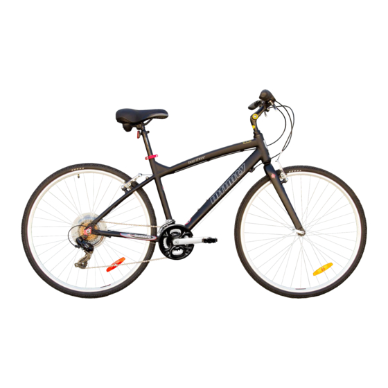
Boss.three 700c Men's Hybrid Bicycle
Here is a picture of your assembled
bicycle.
Be sure to double check that all
quick release and bolts are secure
before riding.
Always wear a helmet.
Handlebar assembly
Seat
Frame
Seat post
Quick Release
A
Incorrect
GETTING STARTED
Open the carton from the top and carfully remove the bicycle. Now remove all ties and
protective wrapping making note of parts as you go along. Do not discard packing
material until assembly is complete to ensure no required parts are accidentally
discarded.
Pedals
HANDLEBAR ASSEMBLY
C
Remove all protective packaging from the handlebar assembly, if not already done.
Turn the fork of the bicycle to face forward. (Note that "forward" means that the wheel
mounting slots are in the furthest forward position, so the wheel axle will be in front of
B
the fork when assembled.) Look for removable decal and information card on the fork
showing the proper direction.
If your model comes equipped with gears and/or handbrakes, you will need to be sure
that the brake cables and shift cables are properly routed. Position the handlebar
assembly as if you were going to install it and take a look at the cables. They should
run in a smooth arc from the shifter or brake lever to the front brakes or cable stop on
the frame. If they are twisted or kinked, the shifting and braking will not work. Rotate
the handlebars around until the cables are taking the smoothest route.
Loosen the center bolt
D
steer tube. Lower the stem until the mark that says "minimum insertion" is no longer
visible. Tighten the stem center bolt so that the handlebar assembly is in line with the
fork. If needed, you can recheck this after the front wheel is installed and re-adjust.
Check handlebar stem clamp bolt
Correct
handlebar cannot move. The angle of the handlebar can be adjusted. To adjust: loosen
all of the handlebar stem clamping bolts and rotate the handlebar to the desired
angle. Be sure that the handlebar stays centered in the stem. Re-tighten the bolts a
little at a time, being sure that the gap between the stem cap and stem stays even.
Repeat tightening each bolt a little bit until handlebar is secure.
www.infinitycycleworks.com
(A)
(B)
enough so that the wedge and stem can slide into the fork
(C)
to be sure they are properly tightened and
ASSEMBLY
VIDEO LINK
(D)
Advertisement

Related Manuals for Infinity Boss.three


Summary of Contents for Infinity Boss.three
-
Page 1: Getting Started
Should you require replacement parts or have any questions pertaining to the assembly of your bicycle, call our service line direct at: Boss.three 700c Men’s Hybrid Bicycle Here is a picture of your assembled bicycle. -
Page 2: Front Wheel
HANDLEBAR ASSEMBLY to o front wheel. Try turning the handlebar. If you can turn it without turning the front wheel, the stem is too loose. Re-align the handlebar with the fron FRONT WHEEL VIDEO: 1. Locate the quick release skewer attached to the spokes of your front wheel (see image GETTING STARTED). - Page 3 NUTTED FRONT WHEEL (for models without quick release front wheel) 1. If the Axle Nuts are already attached to the front wheel axle, begin by removing them with an open end wrench or adjustable wrench. 2. Set the wheel into the front fork 3.
-
Page 4: Pedals And Cranks
PEDALS AND CRANKS Attachment of an incorrect pedal into a crank arm can strip pedal check to ensure your pedals are attached securely and correctly. Look for the letters “R” for right, and “L” for left, stamped on each pedal spindle.
Need help?
Do you have a question about the Boss.three and is the answer not in the manual?
Questions and answers