
Related Manuals for Satel MICRA


Summary of Contents for Satel MICRA
- Page 1 Alarm module with GSM/GPRS communicator MICRA Program version 2.02 micra_en 11/11 SATEL sp. z o.o. ul. Schuberta 79 80-172 Gdańsk POLAND tel. + 48 58 320 94 00 info@satel.pl www.satel.eu...
- Page 2 The latest EC declaration of conformity and product certificates can be downloaded from our website www.satel.pl SATEL's goal is to continually improve the quality of its products, which may result in alterations of their technical specifications and firmware. Current information on the introduced modifications is available on our website.
- Page 3 Changes made to firmware version 2.02 The module can be powered with 12 V DC. Power When logging into GSM network, the module automatically downloads Clock time and date information, if such a service is offered by the GSM network operator. Capability of NC (normally closed) operating mode.
-
Page 4: Table Of Contents
Description of electronics board..................4 Installation.........................5 Installation plan......................6 Estimation of current consumption................7 Cabling ........................7 The MICRA module installation .................7 Connecting detectors and other devices to zones .............7 Connecting siren......................8 Connecting power supply and starting the module ............9 Wireless devices installation ..................10 3.8.1... -
Page 5: Module Features
• Built-in radio waves superheterodyne receiver: – support for up to eight 433 MHz keyfobs manufactured by SATEL; – support for up to eight 433 MHz wireless detectors manufactured by SATEL; – support for MKP-300 wireless keypad. • Non-volatile 1024 event log buffer. -
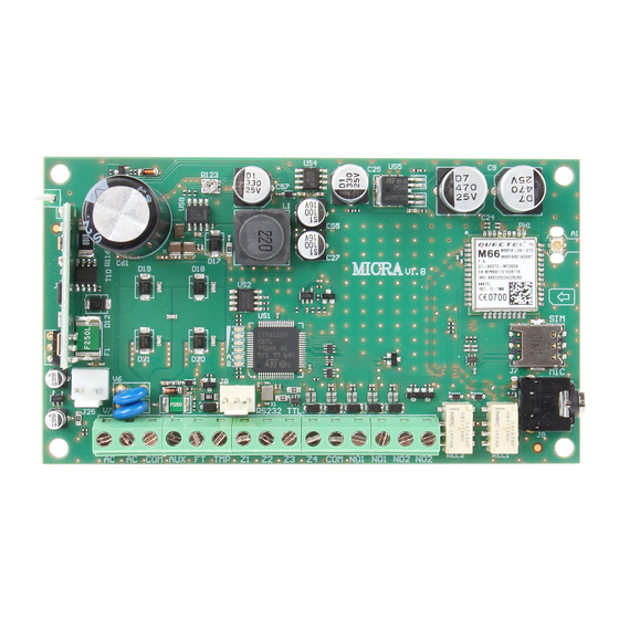
Page 6: Description Of Electronics Board
4 - port RS-232 (standard TTL) enables local programming by means of the GPRS-S program (connection can be made with cables included in the set manufactured by SATEL and designated DB9FC/RJ-KPL). 5 - SIM card socket. It is not recommended to insert the SIM card into its socket before programming the card PIN code in the module (if the card requires entering the PIN code). -
Page 7: Installation
SATEL MICRA Fig. 2. Examples of LED indicated statuses. A (LED A is blinking, the other LEDs are lit up) – GPRS transmission is going on; signal level: 3. B (LED B is blinking, the other LEDs are lit up) – SMS message is being sent or module is calling (CLIP test transmission); signal level: 4. -
Page 8: Installation Plan
SATEL • precision pliers, • flat nose pliers, • drill with a set of drill bits. Fig. 3. MICRA module with connected antenna, battery and transformer, installed in OPU-4 P enclosure. 3.1 I NSTALLATION PLAN If the module is to be a component of alarm system, the installation should be preceded by preparing a plan of arrangement in the premises of all devices to be included in such a system, i.e. -
Page 9: Estimation Of Current Consumption
MODULE INSTALLATION The module PCB contains electronic components sensitive to electric charges. The MICRA module should be installed indoors, in spaces with normal air humidity. The installation place should be inaccessible to unauthorized persons. When selecting the installation place, take into consideration that thick walls, metal partitions, etc. will reduce the radio signal range. -
Page 10: Connecting Siren
The choice of the power supply source should be made conditional upon the previous estimation of current consumption. Fig. 5. An example of connecting NC type detector to the MICRA module (NO type detector is to be connected in the same way). -
Page 11: Connecting Power Supply And Starting The Module
(e.g. by indicating the fuse which protects the module supply circuit). A 12 V / 7 Ah battery should be connected to the MICRA module as backup power supply. Note: If the battery voltage drops below 11 V for longer than 12 minutes (3 battery tests), the module will indicate battery failure. -
Page 12: Wireless Devices Installation
Sometimes, you just need to move the device from ten to twenty centimeters for the transmissions to be correctly received by the module. Only then you can install the device permanently. The MICRA module supports: 1. wireless detectors: – MSD-300 smoke and heat detector, –... -
Page 13: Adding New Wireless Devices
SATEL MICRA 3.8.1 A DDING NEW WIRELESS DEVICES Wireless detectors You can add the wireless devices in the "Options, zones, outputs" tab, "Wireless zones" table: 1. Click your mouse pointer on one of the fields at the detector you want to add. -
Page 14: Remote Programming Using Gprs Technology
MICRA SATEL the available computer COM ports. After activation of the selected COM port, the program will establish communication with the module. 4.2 R GPRS EMOTE PROGRAMMING USING TECHNOLOGY During the remote programming of the module, all functions that require the use of GSM telephone will be disabled. -
Page 15: Description Of The Program
SATEL MICRA 4.3 D ESCRIPTION OF THE PROGRAM 4.3.1 M AIN MENU Fig. 8. Main menu of GPRS-S program. Explanations for Figure 8: - program name. - version of program. - name of data file. - version of module firmware (version number and build date). - Page 16 MICRA SATEL – TCP/IP – communication with the use of GPRS technology. 11 - present voltage at the output of built-in power supply (in the event of AC power loss this is the voltage supplied from battery). 12 - status information about: –...
-
Page 17: Options, Zones, Outputs" Tab
SATEL MICRA – FT – FT output (colors have the same meaning as for the relay outputs);; – MKP-300 – wireless keypad: green – keypad registered; red – keypad tamper; gray – keypad not registered. Under the field corresponding to the wireless keypad, a bar is displayed to illustrate the level of communication between keypad and module. - Page 18 MICRA SATEL Fig. 9. „Options, zones, outputs” tab, when alarm device mode has been selected. Parameters and options Arm status on FT output – option available for the alarm device mode. If it is enabled, the FT output will work as an armed status indicator (it is active, when the module is armed).
- Page 19 SATEL MICRA enables the zone to be disarmed before an alarm is triggered. You can program up to 255 seconds. If value 0 is programmed, violation of the armed 4. D zone type will ELAY trigger an instant alarm. Exit delay – parameter available in the alarm device mode, denoting the time counted from the moment of arming.
- Page 20 MICRA SATEL Fig. 10. Operation manner of analog zone. 0 – no violation. 1 – violation. L-T – voltage level L minus tolerance. L – lower voltage level. L+T – voltage level L plus tolerance. H-T – voltage level H minus tolerance. H – upper voltage level. H+T – voltage level H plus tolerance.
- Page 21 SATEL MICRA ON 1 – violation of the zone will activate the output 1, if the output is of the 5. O UTPUT type. ONTROLLED ON 2 – violation of the zone will activate the output 2, if the output is of the 6.
- Page 22 The test mode will automatically be ended after 30 minutes. Arming will end the test mode. Note: Starting the test mode has no other effect on the operating of MICRA module.
- Page 23 SATEL MICRA SMS control (zones) Bypass – content of the control command that must be included in the SMS message being sent to the module for the zones to be bypassed (blocked). Depending on the module operating mode: communications device – all zones with the "Blocked" option enabled will be blocked.
-
Page 24: Gsm Telephone, Monitoring Stations" Tab
Fig. 11. "GSM telephone, Monitoring stations" tab. Programming MICRA identifier – a sequence of 1 to 8 alphanumeric characters to identify the module. Communication between the program and the module is only possible when the identifier entered in this field is consistent with that stored in the module. No identifier is preprogrammed in the module with factory default settings. - Page 25 SATEL MICRA Initiating number only from list of telephone numbers for messaging – if this option is enabled, the SMS message initiating the remote programming must be sent from a telephone whose number is stored in the module memory in the list of telephone numbers for messaging.
- Page 26 MICRA SATEL module status are not included in the number of transmissions and are not limited. You can enter any value from 0 to 255. Entering 0 means no transmission limit (default: 0). Monitoring station 1 / Monitoring station 2 Notes: •...
- Page 27 SMS message, go over to the "MKP-300 keypad" tab ("Messaging / reporting" table). Note: The CLIP service and SMS message settings are to be programmed in the "MKP-300 keypad" tab, whether or not the MKP-300 keypad is registered in the MICRA system.
-
Page 28: Test Transmissions" Tab
MICRA SATEL CLIP-status – select this field, if an SMS message containing module status information is to be sent in reply to the CLIP from the given telephone number (see: "Send SMS with module status to CLIP" option, "Test transmission" tab). The field is available, if the "Send SMS with module status to CLIP"... - Page 29 SATEL MICRA Event codes for module test transmission The table makes it possible to define the Contact ID codes which will be sent to the monitoring stations for the module test transmission (the code will also be written to the event log).
- Page 30 MICRA SATEL can be programmed. Acknowledgement of the CLIP test transmission receipt will make the module stop repeating such a transmission (e.g. if the test transmission is programmed to be repeated 5 times, but it is already received at the first attempt, the module will not send the other 4 transmissions).
-
Page 31: Clip / Sms Messaging" Tab
SATEL MICRA I – AC voltage loss. – AK – information on the battery status: i – battery full, I – battery low. – OUT 1 ÷ OUT2 – information on relay outputs status OUT 1 ÷ OUT2: o – output inactive, O –... -
Page 32: Reporting" Tab
MICRA SATEL Add input voltage value to message – option available for the communication device mode. If the option is enabled, information on the current voltage value at the zone input will be added to the SMS message about the analog zone status. - Page 33 SATEL MICRA Fig. 14. „Reporting” tab for the alarm device mode. Reporting parameters Note: For the analog zones, the reporting related parameters are to be determined separately for each of the defined thresholds. S1 – select this field if the event code is to be sent to the monitoring station 1.
-
Page 34: Keyfobs" Tab
MICRA SATEL – XYZ – 3-digit event code. Code entering is facilitated by the Contact ID code editor, which you can start by clicking the button, available in the "EVENT" field. Part. – partition number which will be sent in the event code. You can enter numbers and letters from A to F. - Page 35 SATEL MICRA Fig. 15. „Keyfobs” tab. Adding keyfobs – serial number entered manually 1. In the "Serial no." field, enter the serial number of the keyfob to be added. 2. In the "User name" field, enter the name of user.
-
Page 36: Mkp-300 Keypad" Tab
MICRA SATEL „CLIP / SMS messaging” tab Similarly to notification about other events, the information about the use of a keyfob button can be conveyed by means of SMS messages or by using the CLIP service. CLIP T1 – T4 – select the fields of telephones (see: numbers in the list "Telephone numbers for messaging and test transmissions", programmed in the "GSM telephone, Monitoring... - Page 37 SATEL MICRA the field is selected and the module receives no transmission for an hour, it will generate a trouble event – the suitable message will be displayed in the GPRS-S program. Alarm 3 incorrect codes – if this option is enabled, an alarm will be triggered by entering three times an invalid code from the keypad.
-
Page 38: Event Log" Tab
MICRA SATEL specify in the table whether the code relating to any of these events is to be reported to the monitoring station. CLIP T1 – T4 – select the fields of telephones (see: numbers programmed in the "GSM telephone, Monitoring stations" tab, "Telephone numbers for messaging and test transmissions"... -
Page 39: Programming With The Use Of Sms Messages
SATEL MICRA Read – button enables data reading from the module. 4.4 P ROGRAMMING WITH THE USE OF MESSAGES The module can be programmed using SMS messages: • at any moment from the telephone whose number is programmed in the "Telephone numbers for messaging and test transmissions"... -
Page 40: Starting Gprs Reporting
MICRA SATEL – if the module users are to be authorized to remotely control the system by means of SMS messages (arming/disarming, clearing alarms, bypassing/unbypassing zones, controlling outputs), define the suitable control commands. 2. If the module is to be operated by means of keyfobs, click on the "Keyfobs" tab and add the keyfobs (see: description of adding keyfobs, p. -
Page 41: Starting Clip / Sms Messaging
SATEL MICRA – enter the GSM telephone number through which the monitoring station receives SMS messages ("Tel. number (SMS)" field). 3. Define the SMS message format in which the received event codes will be sent to the monitoring station ("GSM telephone, Monitoring stations" tab). -
Page 42: Specifications
MICRA SATEL 6. S PECIFICATIONS Number of hardwired zones ....................4+1 Number of outputs: relay ..................2 low-current, OC type .............1 power ..................1 Supply voltage: ....................18 V AC ±10% Recommended transformer type............TR40VA (40VA / 18VAC) Type of module power supply ....................A Total power supply rating .....................
Need help?
Do you have a question about the MICRA and is the answer not in the manual?
Questions and answers