
Related Manuals for Husqvarna GARDENA SILENO city


Summary of Contents for Husqvarna GARDENA SILENO city
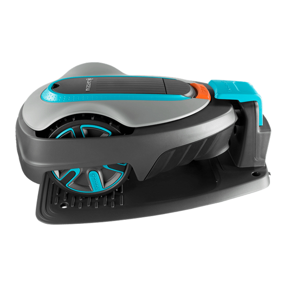
- Page 1 Workshop manual Husqvarna ® Automower 115H ® GARDENA ® SILENO city, smart SILENO city, SILENO life, smart SILENO life McCULLOCH ® ROB S400, ROB S500, ROB S600...
-
Page 2: Table Of Contents
Contents 1 Introduction 6 Repair instructions 1.1 Document description..........3 6.1 The body system..........16 1.2 Servicing tools............3 6.2 The upper chassis..........16 6.3 The lower chassis..........17 6.4 The cutting system..........17 2 Safety 6.5 To mount screws..........17 2.1 Safety definitions............4 6.6 To disassemble the body system......17 2.2 General safety instructions........4 6.7 To disassemble the upper chassis.......19... -
Page 3: Introduction
1 Introduction 1.1 Document description The Workshop manual is intended for dealers and service personnel, and is a supplement to the Operator’s Manual. The following system is used in Workshop manual to make it easier to use: italics is a text that is shown on the •... -
Page 4: Safety
2 Safety 2.1 Safety definitions Warnings, cautions and notes are used to point out specially important parts of the manual. WARNING: Used if there is a risk of injury or death for the operator or bystanders if the instructions in the manual are not obeyed. CAUTION: Used if there is a risk of damage to the product, other materials or the adjacent area if the instructions in the manual are not obeyed. -
Page 5: Symbols On The Product
2.4 Symbols on the product These symbols can be found on the product. Study them carefully. WARNING: Read the user in- structions before operating the product. WARNING: Operate the disa- bling device before working on or lifting the product. It is only safe to carry out in- spection or maintenance on the product when the product is disabled. -
Page 6: Product And Installation
3 Product and installation 3.1 Main components for installation rapidly. Signal quality should always be 100% for satisfactory function. The robotic system involves 4 main components: • Product • Charging station • Power supply • Loop wire Go to the manufacturer's website or read the Operator's manual for further descriptions about the product and 15 m/49 ft. -
Page 7: Charging Station
3.7 Sensors always goes from the guide wire to the left in the connection between guide wire and boundary loop. There are several types of sensors in the product: The strength of the guide signal varies like the A signal depending on the distance to the guide loop. -
Page 8: Testing The Installation
® smart SILENO life and Lawn shield for McCULLOCH are the same function. This function is not available for ® the Husqvarna model. When SensorControl/Lawn shield is activated, the product automatically adjust its mowing times based on how fast the grass grows. This is decided by continuously measuring the blade disc resistance and comparing that to a mean value. -
Page 9: Special Menus
4 Special menus 4.1 Tools menu overview Tools Info History, total History, trip Test Special settings Calibrate General Battery Loop Sensors Motors Key data Reset trip Override Demo Installation values loop lock detection Key data Search Battery Guide Tilt sensor times times capacity... - Page 10 Total running : The total hours the product has used Info - Sensors - Status menu shows: • the wheel motors (cutting and searching). Lifted : When the body is lifted up the lift sensor is • Mower s/n : The product's serial number. This •...
- Page 11 Overview : Shows the average, max and min search • Note: If a wheel motor fails to start and is very time of the last 12 searches. difficult to rotate by hand, the fault is most likely Search times : Shows each of the last 12 searches. •...
-
Page 12: Quick Info (Limited Tools Menu)
4.3.6 Tools - Calibrate Tools - Calibrate menu shows: Guide calibration : The guide wire is calibrated • automatically during the first start-up sequence. A manual calibration may however be necessary, if for example the charging station installation is changed. Place the product in the charging station and start the calibration. -
Page 13: Autocheck Service Tool
5 Autocheck service tool 5.2 Connect the product Autocheck 3 is a PC tool developed for the service of the robotic lawn mowers from Husqvarna Group. It is a 1. Remove the battery cover. Refer to To replace the tool for troubleshooting as well as a database of sold battery on page 24 . -
Page 14: Programming Circuit Boards
Auto test • 5.3.6 Log book Manual test • Log book contains the Fault memory where, for Firmware • example, the product's error codes can be found. • Actions Additional Log book functions are continuously implemented. Log book • Documents •... - Page 15 5.4.3 Programming a new main circuit board If the main circuit board is replaced, the new main circuit board must be programmed. The main circuit board includes information about the product’s serial number. Note: A new main circuit board may for safety reasons only be assigned one serial number which is never changed.
-
Page 16: Repair Instructions
6.2 The upper chassis The upper chassis is structured mechanically around the following modules: 1. Keypad 2. Upper chassis 3. STOP button 4. Height adjustment knob ® • The body system - Husqvarna 16 - Repair instructions 1067 - 001 - 16.04.2019... -
Page 17: The Lower Chassis
2. Rear housing module ® 3. Rear wheel / Rear wheels (only for GARDENA ® ® a) For GARDENA and Husqvarna the top cover SILENO life and smart SILENO life and is attached to the body by clips. Pull the top ® Husqvarna cover up clockwise by hand and remove it. - Page 18 6. Detach it on one side and then pull it out by hand. frame. Note: The springs for the hatch differ between the ® ® models. GARDENA and Husqvarna have two ® springs. McCULLOCH has one spring with sleeve. ®...
-
Page 19: To Disassemble The Upper Chassis
3. Push the clips inwards to remove the STOP button. ® b) Only for Husqvarna . The bumper rear and bumper front are attached to the body with screws. Loosen the 8 screws (Torx 20) and remove the bumpers. -
Page 20: The Circuit Boards
5. Pull the STOP button backwards. 8. Disconnect the power cable (A) from the main circuit board. CAUTION: Always disconnect the power cable first to avoid current spikes that may harm the circuit boards or the battery. 6. Loosen all 12 screws (Torx 20) and remove them. 9. - Page 21 before you start to work on electrical 5. Pull up the front sensor circuit board and remove it. components. CAUTION: Do not touch the circuit board’s components or pin terminals. 6.8.1 To replace the front sensor circuit board CAUTION: Some sensors consists of a Hall sensor and a magnet.
- Page 22 To assemble the upper chassis and system. Refer to the body system on page 28 . ® 5. Only for Husqvarna , loosen the 2 screws into the lower chassis. 11. Connect the product to Autocheck. Select the correct serial number in the log book. Autocheck automatically transfers the operating information saved in the log book.
- Page 23 6. Push down the clips that hold the rear housing 11. Reassemble the rear housing module into the lower module in place. Pull out the rear housing module chassis. backwards and downwards. 12. Reassemble the upper chassis and the body To assemble the upper chassis and system.
-
Page 24: The Battery System
3. The COM circuit bord is held by 2 screws or 2 clips battery to 100% would take too long since the charging (depending on model). Loosen the 2 screws (Torx current is low. The most rational way of using Li-ion 20) or push the 2 clips and remove the circuit board. -
Page 25: To Clean And Replace The Ventilation Filter
To disassemble the 1. Disassemble the body. Refer to body system on page 17 . ® ® 2. Only for Husqvarna and McCULLOCH . Remove the STOP button, refer to step 3-5 in disassemble the upper chassis on page 19 . -
Page 26: To Replace The Body Suspension Parts
7. Reassemble the upper chassis and the body 4. Push the body suspension part into the hole in the To assemble the upper chassis and system. Refer to lower chassis. the body system on page 28 . 6.12 To replace the body suspension parts 1. -
Page 27: The Wheel Motors
5. Loosen 1 screw for the cutting guard and turn the 11. Assemble the cable gland into the lower chassis, To assemble guard counter-clockwise to remove it. and attach a new sealing strip. Refer to the sealing strips on page 28 . 12. -
Page 28: To Assemble The Upper Chassis And The Body System
Refer to 2. Connect the HMI cable to the main circuit board. system on page 17 . 8. Refit the hatch into the clips. Put the frame into ® position (not for Husqvarna ® ® a) For GARDENA and Husqvarna , push the top cover into position. -
Page 29: The Charging Station
3. Lay the other end of the sealing strip above the first 4. The cap is attached with one clip. Remove it by end and then out of the channel. Fasten the sealing gently lifting one side of the cap. strip in the retainer. -
Page 30: To Mount Thread Plugs
To ensure the threads in plastic parts are not damaged: 3. Make sure the plug is screwed in completely so that a good seal is obtained. 1. Carefully turn the screw counter-clockwise until it engages the existing threads in the plastic. The screw will fall slightly by itself when the threads are located correctly in relation to the existing threads in the plastic. -
Page 31: Service
7 Service 7.1 Service schedule The table below contains a checklist of points and actions to be taken when servicing the product. Complete service plans can be found in Autocheck. Every Every Action Explanation year 3rd year Disassemble the body and clean the chassis. Refer to To disassemble the body system on page 17 . -
Page 32: Screw Fasteners
Screw, 5 x 16 mm Torx 20 Rear housing module to lower chassis**** Screw 5x16 mm Torx 20 *accessory **only smart SILENO city, smart SILENO life ® ***only McCULLOCH ® ****only Husqvarna 32 - Service 1067 - 001 - 16.04.2019... -
Page 33: Troubleshooting
8 Troubleshooting 8.1 Messages The table below contains fault and information messages which can appear in the product. Note: Refer to the Operator's manual for more information about how to rectify errors. Messages Number Message Cause Action BATTERY Low battery The product cannot find the charging Break in the guide wire. - Page 34 Messages Number Message Cause Action MOTORS 20/21 Wheel motor blocked, Grass or other object has wrapped Check the drive wheel and remove any right/left around the drive wheel. objects. 22/23 Wheel drive problem, The wheel motor is faulty Check the wheel motors’ function when right/left idling.
- Page 35 Messages Number Message Cause Action INSTALLATION No loop signal Boundary wire broken. Check the signal given by the LED on Loop sig- the charging station. Refer to nal on page 41 . The boundary wire is not connected to Check that the boundary wire connec- the charging station tors are fitted properly to the charging station.
- Page 36 Messages Number Message Cause Action INSTALLATION Mower lifted The lift sensor has been activated due Free the product and rectify the reason. to the product getting stuck. Lift sen- One of the lift senor magnets is inver- Check the magnet. Refer to sors on page 7 .
- Page 37 Messages Number Message Cause Action INTERNAL DIAGNOSTICS 18/19 Collision sensor prob- The product is trapped. Free the product and rectify the reason. lem rear/front Loop sensor problem, The cabling to the sensor circuit board Check the levels for the A signal. Refer Tools - Info on page 9 .
-
Page 38: Symptoms
Messages Number Message Cause Action INTERNAL DIAGNOSTICS Electronics problem Display problem Replace the HMI circuit board. Electronics problem The parameter for the type of product The parameter can only be entered at is different in the HMI circuit board and the initial programming of the main cir- main circuit board. - Page 39 Note: Refer to the Operator's manual for more information about how to rectify errors. 8.2.1 Symptoms during mowing Symptom Cause Action Uneven mowing results The product works too few hours per day. Increase the working hours. Working area too large. Try to limit the working area or extend the working time.
- Page 40 8.2.2 Symptoms during searching Symptom Cause Action The product runs, but the The product is searching for the charging This behaviour is normal and no action is blade disc does not rotate station. The blade disc does not rotate required. when the product is searching for the charging station.
-
Page 41: Loop Signal
8.2.5 Miscellaneous symptoms Symptom Cause Action The display is lit but but the The main circuit board is faulty. Reprogram the main circuit board using Programming a keypad does not lead to any Autocheck. Refer to blocked main circuit board on page 14 . reaction To replace Faulty keypad. -
Page 42: To Find A Break In The Boundary Loop
select the maximum cutting height the first week after installation and then lower the height one to two steps at a time every week until the desired cutting height has been reached. A wire break can be found by using a break detection tool from the manufacturer or with the manual method that is described in the Operator's manual. -
Page 43: Transportation, Storage And Disposal
9 Transportation, storage and disposal 9.1 Transportation • If you keep the charging station indoors, disconnect and remove the power supply and all the connectors The supplied Li-ion batteries obey the Dangerous Goods from the charging station. Put the end of each Legislation requirements. -
Page 44: Technical Data
10 Technical data 10.1 Technical data For the technical data, refer to Operator's manual and the manufacturer's website. 44 - Technical data 1067 - 001 - 16.04.2019... - Page 45 1067 - 001 - 16.04.2019 Technical data - 45...
- Page 46 46 - Technical data 1067 - 001 - 16.04.2019...
- Page 47 1067 - 001 - 16.04.2019 Technical data - 47...
- Page 48 ORIGINAL INSTRUCTIONS We reserve the right to make changes without prior notice. Copyright © 2019 Husqvarna AB. All rights reserved. 114 12 39-26 www.husqvarna.com www.gardena.com www.mcculloch.com 2019-03-04...
Need help?
Do you have a question about the GARDENA SILENO city and is the answer not in the manual?
Questions and answers