
Related Manuals for Gentex HGU-55/P


Summary of Contents for Gentex HGU-55/P
- Page 1 Operation and Maintenance Instructions with Illustrated Parts Breakdown Lightweight HGU-55/P Helmet Assembly © 2011 Gentex Corporation...
- Page 3 When you replace components or install additional components on Gentex products, always use genuine factory-new Gentex parts. This will ensure a correct fit and maintain the safety of the product. Use of non-Gentex parts (salvage, refurbished, etc.) for replacement or additional installation will void any product warranty and may compromise the safety of the user.
-
Page 5: Table Of Contents
Contents CHAPTER 1: INTRODUCTION AND GENERAL INFORMATION 1-1 GENERAL 1-2 HELMET DESCRIPTION 1-3 HELMET COMPONENTS 1-4 EQUIPMENT, TOOLS, AND MATERIALS NEEDED CHAPTER 2: HELMET PREPARATION AND OPERATION 2-1 GENERAL 2-2 HELMET FITTING 2-2 1 Determining Helmet Size 2-2 2 Fitting the TPL, SCL, or XLiner 2-2 3 Checking Helmet Fit and Operation 2-3 BAYONET RECEIVER INSTALLATION 2-3 1 Installing Standard Bayonet Receivers... - Page 6 3-2 3 Post-Flight Inspection 3-2 4 Periodic Inspection 3-3 CLEANING 3-4 REPLACEMENT OF COMPONENTS 3-4 1 Replacement of Jack Holder 3-4 2 Replacement of Earseals 3-4 3 Replacement of Earcups or Earphones 3-4 4 Replacement of Cable 3-4 5 Replacement of Bayonet Receivers 3-4 6 Replacement of TPL, SCL, or XLiner 3-4 7 Replacement of Energy-Absorbing Liner 3-4 8 Replacement of Integrated Chin/Nape Strap Assembly...
-
Page 7: Chapter 1: Introduction And General Information
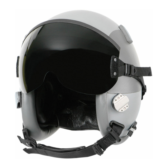
Chapter 1: Introduction and General Information CHAPTER 1: INTRODUCTION AND GENERAL INFORMATION 1-1 GENERAL This chapter provides a description of the HGU-55/P Helmet. It also includes lists of the equipment, tools, and materials needed to maintain the helmet. 1-2 HELMET DESCRIPTION The HGU-55/P Helmet (Figure 1-1) provides basic head protection, sound attenuation, and communications for aircrew personnel. -
Page 8: Helmet Components
Visors. Each helmet includes two snap-on visors (one clear and one sunshade) and a visor cover. Helmet-visor configurations are as follows: • HGU-55/P helmet with MBU-12/P visors: 81D5330-7 (Medium), 81D5330-8 (Large), or 81D5330-9 (X-Large) • HGU-55/P helmet with high-speed visors: 81D5330-13 (Medium), 81D5330-14 (Large), or 81D5330-15 (X-Large) •... - Page 9 Chapter 1: Introduction and General Information XLiner Visor cover Helmet shell Visor Leather buffer Pile fastener Earcup Earphone Energy- absorbing liner Jack holder Nape pad Cable Clamp Clamp Edgeroll Chin strap Standard Anti-snag bayonet receiver kit receiver spacer kit Figure 1-2. Helmet Components...
-
Page 10: Equipment, Tools, And Materials Needed
Chapter 1: Introduction and General Information 1-4 EQUIPMENT, TOOLS, AND MATERIALS NEEDED This section provides information about the equipment, tools, and consumable materials needed for helmet preparation and maintenance. Table 1-1 lists the necessary equipment. Table 1-2 lists the required tools. Table 1-3 lists the consumable materials used in the preparation and maintenance of the helmet. - Page 11 Chapter 1: Introduction and General Information Table 1-3. Consumable Materials ITEM PURPOSE Plastic sheeting To make it easier to position the earcups during the helmet fit check Pencil To mark the helmet shell for installation of the bayonet receivers Adhesive, polychloroprene To attach the loose portion of the helmet pile (MIL-A-5540, Class 3 or equivalent) fasteners after the bayonet receivers are installed...
-
Page 13: Chapter 2: Helmet Preparation And Operation
Chapter 2: Helmet Preparation and Operation CHAPTER 2: HELMET PREPARATION AND OPERATION 2-1 GENERAL This chapter includes instructions for the tasks required to prepare the helmet for use. These tasks include helmet fitting, familiarizing the aircrew member with the operation of the helmet, and installing bayonet receivers. -
Page 14: Determining Helmet Size
Chapter 2: Helmet Preparation and Operation 2-2 1 Determining Helmet Size To determine helmet size, you measure the aircrew member's head length and head width. After you make these measurements, you then compare the measurements to established size data and select the helmet size accordingly. Proper fitting of the helmet is imperative for the safety of the aircrew member. -
Page 15: Fitting The Tpl, Scl, Or Xliner
• The dimensions shown in Table 2-1 are intended as guidelines. At times, the next smaller or larger size may be needed. • If the measurements fall into different size ranges, select the larger size. Table 2-1. Size Data for HGU-55/P Head Length, inches (mm) Maximum Head Width, inches (mm) Helmet Size 7.2 to 7.8 (183 to 198) -
Page 16: Checking Helmet Fit And Operation
Chapter 2: Helmet Preparation and Operation 2-2 3 Checking Helmet Fit and Operation Once you have determined the correct helmet size and custom-fitted the TPL, you must ensure that the helmet is properly fitted and adjusted to the aircrew member, as well as familiarize the aircrew member with proper helmet operation. - Page 17 Chapter 2: Helmet Preparation and Operation 5. Have the pilot fasten and adjust the chin strap as follows (Figure 2-6): a. Snap the chin strap. b. Adjust the end of the chin strap so that the nape pad fits snugly against the back of the head.
- Page 18 Chapter 2: Helmet Preparation and Operation 11. Confirm that the pilot is comfortable while wearing the helmet. If the pilot is comfortable, proceed to Step 12. If the helmet is too tight, or pressure points exist, re-fit the TPL, SCL. or XLiner (Paragraph 2-2.2).
- Page 19 Chapter 2: Helmet Preparation and Operation 17. Check the overall fit; the helmet should be snug, yet comfortable. Attempt to rock the helmet back and forth on the head; the helmet should not move. If the fit is correct, go to Step 18. If the helmet moves, it may be too loose.
- Page 20 Chapter 2: Helmet Preparation and Operation 20. With the helmet still on the pilot's head, remove the plastic sheeting from behind the earcups. 21. If the chin strap is too long after it is Trim line adjusted, mark a trim line at the end of the chin strap approximately ENLARGED VIEW,...
-
Page 21: Bayonet Receiver Installation
Chapter 2: Helmet Preparation and Operation 2-3 BAYONET RECEIVER INSTALLATION The standard bayonet receiver kit (Paragraph 2-3.1) is included for installation on all helmet configurations. The anti-snag bayonet receiver kit (Paragraph 2-3.2) is included for installation on helmet part numbers 81D5330-13, 81D5330-14, and 81D5330-15 and is designed to prevent the helmet bayonet receivers from snagging on objects. - Page 22 Chapter 2: Helmet Preparation and Operation Procedure Install the bayonet receiver parts on the helmet as follows: 1. Raise the visor; have the aircrew member don the properly fitted helmet. 2. Insert the mask bayonets into the bayonet receivers to the second locking position. Ensure that all straps are fully extended, have equal tension, and flow smoothly from the mask to the facepiece and the bayonets.
- Page 23 Chapter 2: Helmet Preparation and Operation 7. Referring to Figure 2-17, carefully align the receiver within the traced outline and mark the two screw holes for drilling. Repeat for the other side. 8. Referring to Figure 2-18, detach the earcups from the pile fasteners, and peel back the pile fasteners.
- Page 24 Chapter 2: Helmet Preparation and Operation CAUTION In Step 11, do not tighten either screw in the receiver until both screws have been started, or you might cross-thread the receiver assembly. 11. Referring to Figure 2-20, do the following: a. Insert the screws through the lock washers and the backing plate in that order. b.
-
Page 25: Installing Anti-Snag Receiver Spacer Kit
Chapter 2: Helmet Preparation and Operation 2-3 2 Installing Anti-Snag Receiver Spacer Kit The anti-snag receiver spacer kit is intended for installation on helmets that already have the standard bayonet receiver kit installed. Before you install the receivers, you must ensure that the helmet has been properly fitted as described in Paragraphs 2-2.1, 2-2.2, and, 2-2.3;... - Page 26 Chapter 2: Helmet Preparation and Operation 3. Referring to Figure 2-23, remove Screws the two screws, the two washers, Lock washers and the backing plate from the inside of the helmet to detach Backing plate the existing bayonet receiver assembly and the spacer on one side of the helmet.
- Page 27 Chapter 2: Helmet Preparation and Operation When drilling, position your hands away from the drill bit to avoid injury CAUTION When drilling, hold the drill perpendicular to the helmet to prevent damage. NOTE: Before drilling full-size holes in the Hole to drill helmet shell, it is advisable to drill pilot holes with a #52 (0.0625") drill bit.
- Page 28 Chapter 2: Helmet Preparation and Operation 8. Apply a thin, even coat of polychloroprene adhesive to the back of the peeled-away portion of both pile fasteners and to the inside surface of the helmet shell where the pile fasteners were peeled away. Do not allow the adhesive to contact the backing plates, the screws, or the retention assembly hardware.
-
Page 29: Operation
Chapter 2: Helmet Preparation and Operation 2-4 OPERATION This section contains a summary of the helmet operational tasks described in the fitting and installation sections of this chapter. Operational tasks include donning the helmet, fastening and adjusting the chin strap, operating the visor, and connecting the mask microphone cord to the helmet connector. -
Page 30: Operating Visor
Chapter 2: Helmet Preparation and Operation 2-4 3 Operating Visor Cover Operate the visor as follows: VISOR COVER INSTALLATION 1. Referring to Figure 2-31, grasp the visor in the center and pull the visor slightly away from the helmet. 2. Move the visor up or down. When the visor is up, ensure that the top edge of the visor is against the two bump stops. -
Page 31: Chapter 3: Helmet Maintenance
3-2 INSPECTIONS Proper care and use of the HGU-55/P helmet assembly is essential to ensure optimum performance during emergencies and routine operations. The helmet must be inspected at regular intervals to ensure that it is in serviceable condition. These intervals are described below. -
Page 32: Post-Flight Inspection
Chapter 3: Helmet Maintenance 3. Ensure that the chin strap and nape strap have been properly adjusted for a snug fit and are securely attached to the helmet shell. Cracks in the visor are not acceptable. Cracks will weaken the visor and may cause the visor to fail, creating additional hazards during ejection. -
Page 33: Periodic Inspection
Chapter 3: Helmet Maintenance 2. Inspect the edgeroll for loose edges or damage such as cuts, tears, or holes. NOTE: Advise the aircrew member not to set the helmet on the canopy edge, boarding ladders, or pylons to prevent damage to the leather edgeroll. 3. - Page 34 Chapter 3: Helmet Maintenance NOTES: • As a result of this inspection, any component found to be defective will be repaired or replaced as necessary. • If any items are to be replaced, refitting of the helmet and mask may be necessary. Perform the periodic inspection as follows: 1.
-
Page 35: Cleaning
Chapter 3: Helmet Maintenance 13. Check the visor attaching hardware to ensure that the visor is securely attached to the helmet. 14. Ensure that the visor fits the helmet snugly, with enough resistance to require pulling the visor away from the helmet to raise or lower it. 15. - Page 36 Chapter 3: Helmet Maintenance Procedure Clean the helmet as follows: 1. Helmet shell: Clean with mild detergent and clean cloth; for stains, use a soft-scrub type of detergent or equivalent. Do not use waxes or solvents as they may deteriorate the paint or damage the helmet.
- Page 37 Chapter 3: Helmet Maintenance Cover Cover on layers Cover installed Hole (two places) Label Figure 3-1. Installing TPL or SCL Cover Figure 3-2. Installing TPL or SCL into Helmet CAUTION • Prolonged exposure to excessive heat can damage the TPL or SCL. Do not store the helmet in a closed cockpit or automobile where temperatures can exceed 200ºF (93.3ºC) on an 85ºF(30ºC) day.
-
Page 38: Replacement Of Components
Chapter 3: Helmet Maintenance 3-4 REPLACEMENT OF COMPONENTS The life support technician shall replace defective components. This section provides procedures for component replacement. 3-4 1 Replacement of Jack Holder Parts Required Jack holder, chrome finish (78B4170) Jack holder, black anodized finish (78B4170-1) Tools/Materials Required None Procedure... -
Page 39: Replacement Of Earseals
Chapter 3: Helmet Maintenance 3-4 2 Replacement of Earseals Parts Required Earseals (75C2990) Tools/Materials Required None Procedure Referring to Figure 3-4, replace the earseals as follows: 1. Detach the earcups from the pile fasteners inside the helmet. 2. Note how the existing earseals are installed on the earcups; then remove the earseals from the earcups. -
Page 40: Replacement Of Earcups Or Earphones
Chapter 3: Helmet Maintenance 3-4 3 Replacement of Earcups or Earphones Parts Required Earcups (80C4758), quantity of 2 Earphones (69B2032), quantity of 2 Tools/Materials Required • Jeweler’s screwdriver • Isopropyl alcohol (70 percent solution) or soap and water Procedure 1. Referring to Figure 3-5, pull the earphone out the earcup as follows: a. - Page 41 Chapter 3: Helmet Maintenance 2. Referring to Figure 3-6, disconnect the Earcup earphone from the cable as follows: Earphone a. Use a jeweler’s screwdriver to loosen (not remove) the set screws Grommet on the back of the earphone. b. Withdraw the cable leads from the earphone.
-
Page 42: Replacement Of Cable
Chapter 3: Helmet Maintenance 3-4 4 Replacement of Cable Parts Required Cable (77D3662) Tools/Materials Required • Jeweler’s screwdriver • Isopropyl alcohol (70 percent solution) or soap and water Procedure Replace the cable as follows: 1. Referring to Paragraph 3-4.3, perform Steps 1-2 to remove the cable leads from both earcups. -
Page 43: Replacement Of Bayonet Receivers
Chapter 3: Helmet Maintenance d. Withdraw the cable leads through the hole in the helmet shell. e. Install the leads of the replacement cable into the helmet through the hole in the helmet shell. Ensure that the longer cable lead is positioned toward the right side of the helmet (as worn) inside the helmet. -
Page 44: Replacement Of Energy-Absorbing Liner
Chapter 3: Helmet Maintenance 3-4 7 Replacement of Energy-Absorbing Liner Parts Required Energy-absorbing liner, Medium (85D7081-1); Large (85D7082-1); or X-Large (85D7083-1) Tools/Materials required Thin, flexible metal spatula Procedure 1. Remove the energy-absorbing liner as follows. a. Remove the TPL or XLiner to expose the energy-absorbing liner. b. - Page 45 Chapter 3: Helmet Maintenance NOTE: Before you install the replacement liner (Steps 2 and 3), ensure all attaching hardware for visor configuration, which will be covered by liner, is in place. You can also cover the interior hardware with masking tape to ease installation of the liner. 2.
-
Page 46: Replacement Of Integrated Chin/Nape Strap Assembly
Chapter 3: Helmet Maintenance 3-4 8 Replacement of Integrated Chin/Nape Strap Assembly Parts Required Integrated chin/nape assembly, Medium (90D7916-4), Large (90D7916-5) or X-Large (90D7916-6) Tools/Materials Required • Thin, flexible metal spatula • Torque screwdriver • Flat-tip screwdriver • Optional: Hook made from wire coat hanger Procedure 1. - Page 47 Chapter 3: Helmet Maintenance 2. Referring to Figure 3-13, withdraw the straps from the slots in the helmet shell. 3. Again referring to Figure 3-13, install the replacement chin/nape assembly as follows: a. Insert the strap with the buckle through the slot in the left side (as worn) of the helmet shell.
-
Page 48: Replacement Of Visor
Chapter 3: Helmet Maintenance 3-4 9 Replacement of Visor Parts Required Visor, MBU-12/P: Clear (81D5189-3); or Neutral (81D5189-4); or Visor, MBU-20/P: Clear (89D7697-1); or Neutral (89D7697-2) or Visor, High-Speed: Clear (04D11873-1): or Neutral (04D11873-3) Tools/Materials Required None Procedure 1. Unsnap the existing visor from the helmet from back to front. 2. -
Page 49: Painting
Chapter 3: Helmet Maintenance 3-5 PAINTING This section covers painting procedures for the helmet shell and the chrome bayonet receivers. 3-5 1 Painting Helmet Shell • Keep all electrical equipment away from paint materials. Always work with adequate ventilation. • When spraying primer (MIL-P-23377), wear a respirator NSN 4240-01-108-4172 with filter NSN 4240-115-0590 (or equivalent) neoprene gloves, and safety glasses or goggles. - Page 50 Chapter 3: Helmet Maintenance Touch-up This procedure will not restore the original appearance of the polyurethane paint. The original appearance can only be restored by re-coating the entire painted surface after a repair is made. Perform the touch-up as follows: 1.
-
Page 51: Painting Chrome Bayonet Receivers
Chapter 3: Helmet Maintenance 3-5 2 Painting Chrome Bayonet Receivers The chrome bayonet receivers may be painted to a dull gray finish in order to minimize reflection and aid in escape and evasion tactics. • Keep all electrical equipment away from paint materials. Always work with adequate ventilation. -
Page 53: Chapter 4: Replacement Parts And Optional Items
Chapter 4: Replacement Parts and Optional Items CHAPTER 4: REPLACEMENT PARTS AND OPTIONAL ITEMS This chapter includes an Illustrated Parts Breakdown for replacement parts for the HGU-55/P helmet. It also includes lists of optional items that are not included with the helmet. For more information, contact Gentex Corporation, Carbondale, PA., USA, www.gentexcorp.com. - Page 54 Chapter 4: Replacement Parts and Optional Items Figure 4-1. HGU-55/P Helmet Components...
- Page 55 Chapter 4: Replacement Parts and Optional Items FIG. NO. PART NO. CAGE DESCRIPTION QTY. 81D5330-7 97427 HGU-55/P Helmet, Medium, MBU-12/P Visors 81D5330-8 97427 HGU-55/P Helmet, Large, MBU-12/P Visors 81D5330-9 97427 HGU-55/P Helmet, X-Large, MBU-12/P Visors 81D5330-13 97427 HGU-55/P Helmet, Medium, High-Speed Visors...
- Page 56 Chapter 4: Replacement Parts and Optional Items FIG. NO. PART NO. CAGE DESCRIPTION QTY. 80C4754-3 97427 Headset Assembly (See Figure 4-3 for breakdown) 79C4416-20 97427 Earcup Spacer Pad Set 78B4170 97427 Jack Holder 90D7916-4 97427 Integrated Chin/Nape Assembly, Medium, Black A, D, G (See Figure 4-4 for breakdown) 90D7916-5...
- Page 57 Chapter 4: Replacement Parts and Optional Items Figure 4-2. TPL Kit FIG. NO. PART NO. CAGE DESCRIPTION QTY. 85D7087-1P 97427 TPL Kit, Medium A, D, G 85D7087-2P 97427 TPL Kit, Large B, E, H 85D7087-3P 97427 TPL Kit, X-Large C, F, I 88D7518-1 97427 Layer Assembly, Medium...
- Page 58 Chapter 4: Replacement Parts and Optional Items Figure 4-3. Headset Assembly FIG. NO. PART NO. CAGE DESCRIPTION QTY. 80C4754-3 97427 Headset Asssembly 80C4758 97427 Earcup 67A1697 97427 Filler Pad 69B2032 97427 Earphone, H-143/AIC 70A2249 97427 Earphone Holder 75C2990 97427 Earseal 77D3662 97427 Cord Assembly, CX4708 A/AIC...
- Page 59 Chapter 4: Replacement Parts and Optional Items Figure 4-4. Integrated Chin/Nape Assembly FIG. NO. PART NO. CAGE DESCRIPTION QTY. 90D7916-4 97427 Integrated Chin/Nape Assembly, Medium, Black A, D, G 90D7916-5 97427 Integrated Chin/Nape Assembly, Large, Black B, E, H 90D7916-6 97427 Integrated Chin/Nape Assembly, X-Large, Black C, F, I...
- Page 60 Chapter 4: Replacement Parts and Optional Items Figure 4-5. Anti-Snag Receiver Spacer Kit FIG. NO. PART NO. CAGE DESCRIPTION QTY. 05A12024-1 97427 Anti-Snag Receiver Spacer Kit D, E, F MS51957-27B 97427 Screw, Pan-Head, 6-32 x 5/16 MS51957-30B 97427 Screw, Pan-Head, 6-32 x 1/2 MS35335-58 97427 Washer, Lock, External Tooth, #6...
- Page 61 Chapter 4: Replacement Parts and Optional Items Figure 4-6. Bayonet Receiver Kit FIG. NO. PART NO. CAGE DESCRIPTION QTY. 82A5614-20 97427 Bayonet Receiver Kit MS51957-29 97427 Screw, Pan-Head, Cross-Recessed, 6-32 x 7/16 MS35335-58 97427 Washer, Lock External Tooth, #6 82A5722 97427 Backing Plate 80B4858...
-
Page 62: Optional Items
Chapter 4: Replacement Parts and Optional Items 4-2 OPTIONAL ITEMS Optional items include additional components (not included with the helmet) that are available for installation on the helmet, as well as alternate helmet configurations. Contact Gentex Corporation (www.gentexcorp.com) for more information. 4-2 1 Additional Components The following components are available. - Page 63 Chapter 4: Replacement Parts and Optional Items Gray leather comfort earpads Leather earpads (Figure 4-10) • Gray: 79C4473-3 • Black: 89C7735-1 The gray leather comfort earpads are designed to hold the earphones directly inside. Black leather earpad set The black leather earpad sets contain plastic earcups (with earphone holders inside) and Figure 4-10.
- Page 64 Chapter 4: Replacement Parts and Optional Items Visor High-speed visor modification kit (Figure 4-13) • Kit: 05B11943-3 This kit is designed for enhanced windblast performance. The kit includes a neutral visor and a specially designed rubber edgeroll Edgeroll cover cover that provides friction holding of the Figure 4-13.
- Page 65 • Left-hand: 95D8985-1 Female QD • Right-hand: 95D8985-2 This kit integrates the HGU-55/P with the man-worn COMBAT EDGE pressure breathing for G (PBG) system to reduce Fasteners the probability of G-induced loss of consciousness (GLOC) during high- Feed tube performance flight.
-
Page 66: Alternate Helmet Configurations
Chapter 4: Replacement Parts and Optional Items 4-2 2 Alternate Helmet Configurations Variations of the HGU-55/P helmet are available with special components factory-installed for convenience. Lightweight HGU-55/P COMBAT EDGE helmet (Figure 4-21) • Medium: 06D12280-1 • Large: 06D12280-2 • X-Large: 06D12280-3... - Page 67 Chapter 4: Replacement Parts and Optional Items Helmets with boom microphones Helmets are available with various types of boom microphones installed for airlift or trainer use. These include wire booms and flex booms, as well as dynamic and electret microphones and communications cords.
- Page 68 Chapter 4: Replacement Parts and Optional Items TPL® and XLiner® are registered trademarks of Gentex Corporation. SCL™ is a trademark of Gentex Corporation.
- Page 70 TP0351 DECEMBER 2011...
Need help?
Do you have a question about the HGU-55/P and is the answer not in the manual?
Questions and answers