Chapters
Table of Contents

Related Manuals for TANDBERG TT1260


Summary of Contents for TANDBERG TT1260
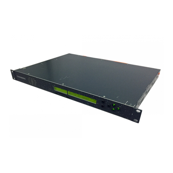
- Page 1 ST.TM.E10100.1 Issue 1 ENGLISH (UK) INSTRUCTION MANUAL TT1260 Standard Definition Professional Receiver/Decoder Software Version 2.1 (and later) TT1260/DIRBAS and Options Typical TT1260 Satellite Receiver or Decoder...
- Page 2 This document and the information contained in it is the property of TANDBERG Television Ltd and may be the subject of patents pending and granted. It must not be used for commercial purposes nor copied, disclosed, reproduced, stored in a retrieval system or...
-
Page 3: List Of Contents
Annex A: Glossary Annex B: Technical Specification Annex C: Menus Annex D: Using the TT1260 with the TANDBERG Director System Annex E: Language Abbreviations Annex F: Factory Defaults Annex G: Quick Reference Guide Instruction Manual: TT1260 Standard Definition Professional Receiver/Decoder ST.TM.E10100.1... - Page 4 Preliminary Pages Index Forms Service/Repair Order Form Page iv Instruction Manual: TT1260 Standard Definition Professional Receiver/Decoder ST.TM.E10100.1...
-
Page 5: About This Manual
About this Manual This manual provides instructions and information for the installation and operation of the TT1260 1U digital integrated Receiver/Decoder (IRD). It should be kept in a safe place for reference during the life of the equipment. Further copies of this manual can be ordered from the address shown on page vii. -
Page 6: Warnings, Cautions, And Notes
EMC Compliance This equipment is certified to the EMC requirements detailed in Annex B, Technical Specification. To maintain this certification, only use the leads supplied or if in doubt contact TANDBERG Customer Services. Page vi WARNINGS... CAUTIONS... -
Page 7: Contact Information
All levels are supported by one or more service performance reviews to ensure the perfect partnership between TANDBERG Television and your business. Levels of Support We offer a number of support service levels so you can choose the one most appropriate to your business requirements. -
Page 8: Technical Training
Preliminary Pages Technical Training Training Courses TANDBERG Television provides a wide range of training courses on the operation and maintenance of our products and on their supporting technologies. TANDBERG can provide both regularly scheduled courses and training tailored to individual needs. Courses can be run either at your premises or at one of our dedicated training facilities. -
Page 9: Table Of Contents
(BISS)...1-17 1.6.6 Rear Panel ...1-17 List of Figures Figure 1.1: Front View of a TT1260 Satellite Receiver... 1-3 Figure 1.2: Make-up of TT1260 Marketing Numbers... 1-3 Figure 1.3: Typical Satellite Compression System ... 1-10 Figure 1.4: What the Satellite Receiver Does... 1-11 Figure 1.5: Typical Download Transmission System... - Page 10 Table 1.1: Hardware Marketing Codes...1-4 Table 1.2: Software Key Marketing Codes...1-4 Page 1-2 Table 1.3: Main Features of the Decoder Range... 1-5 Table 1.4: Main Features of the Satellite Receiver Range ... 1-5 Instruction Manual: TT1260 Standard Definition Professional Receiver/Decoder ST.TM.E10100.1...
-
Page 11: Instruction Manual: Tt1260 Standard Definition Professional Receiver/Decoder St.tm
Scope of this Manual 1.1.1 Who Should Use this Manual This manual is written for operators/users of the TT1260 Professional Receivers and Decoders. It describes the unit’s functions and operation. The manual is written to assist in the installation and day-to-day care and operation of the unit. -
Page 12: Marketing Codes
(#6). The menus are described in Annex C, Menus. Page 1-4 Engineering Description Number E10100 TT1260 Base unit with Director Smart Card reader hardware, chassis S12316 Alarm Relay Card S12495 ASI Input Card, chassis backplate for ASI Input Card S12496... -
Page 13: Table 1.4: Main Features Of The Satellite Receiver Range
8PSK TT1260/SWO/16QAM 16QAM Satellite TT1260/HWO/QPSK QPSK NOTE… All models have analogue outputs as standard. Instruction Manual: TT1260 Standard Definition Professional Receiver/Decoder ST.TM.E10100.1 Input Data-rate Inputs 2 x ASI 0.350-160 Mbit/s Inputs Input Frequency Input Symbol rate FEC Rates Digital 2 x 8PSK 950 –... -
Page 14: Summary Of Features
Introduction Summary of Features 1.2.1 Main Features The TT1260 is fully compliant with the appropriate sections of the MPEG-2 , DVB-S features: · Front Panel Controls and Indications: ² A vertical split two line x 40 character back-lit dot matrix LCD... - Page 15 ² VideoGuard Director ² TANDBERG Television Signal Protection · TANDBERG Director system: ² Over-air remote control is available if the TT1260 is used as part of a TANDBERG Director system (Over-air software downloading, Re-start, Tuning and Retuning etc.) NOTES… The TANDBERG Director system GUI counts the inputs from zero (i.e. 0, 1).
-
Page 16: Inputs
Introduction · Control Methods: ² Front Panel User Interface ² Asynchronous serial remote control ² Over-air remote control (TANDBERG Director system) (optional) 1.2.2 Inputs ASI Inputs (Decoders) Two BNC connectors support both byte-mode and single packet burst mode. L-Band Inputs Two F-type connectors connect the L-band output of a suitable LNB either directly or via a suitable attenuator giving lightning and surge protection. -
Page 17: Conditional Access And Scrambling
There is a 25-way D-type connector on the optional Alarm Relay Card (TT1260/HDC/ALRM) with six relays for failure monitoring for NCP over-air. The operator can define (using the Alarm Menu pages) which alarm conditions that drive the relays and also the general front-panel ALARM LED. -
Page 18: The Satellite Receiver
The Satellite Receiver 1.3.1 Typical Satellite System The TT1260 Satellite Receiver is a component of the MPEG-2/DVB compliant range of TANDBERG Television equipment. It is designed for use by broadcasters and distributors of video, audio and data services over satellite. -
Page 19: Input Connections
Figure 1.4: What the Satellite Receiver Does Instruction Manual: TT1260 Standard Definition Professional Receiver/Decoder ST.TM.E10100.1 Low-Noise Block Tune to a satellite L-band channel... -
Page 20: Over-Air Software Download (Tandberg Director Systems)
Over-air Software Download (TANDBERG Director Systems) The TT1260 Satellite Receiver is shipped with the appropriate software installed, but it is designed to allow replacement of this code by new versions of software transmitted over-air. The new code is downloaded as a background task in the same transport stream as used for the normal transmission of services. -
Page 21: The Decoder
1.4.1 Typical Decoder System The Decoder is a component of TANDBERG Television’s range of equipment. It is designed for use by broadcasters and distributors of video and audio services. It can be used as a transport stream monitor or to decode signals received over a telecommunications network. -
Page 22: Input Connections
Receiver (dependent upon options fitted). The unit remains in the chosen control mode until another mode is requested. NOTE… Local (Front Panel) Control is the factory default if TANDBERG Director is not installed. Page 1-14 Network Adapter Unit... -
Page 23: Front Panel (Local) Modes
NCP control mode. NOTE… Front Panel mode is the factory default for Receivers used in a TANDBERG Director system. To switch to Director NCP mode refer to Section 3.8, Setting Up a System. All Front Panel and Serial Remote commands are ignored except the operating mode. -
Page 24: Guided Tour
Introduction Guided Tour 1.6.1 Construction The TT1260 is constructed using a screened self-ventilated modular system; all operational inputs and outputs are via rear-panel connectors. The unit may be operated freestanding or mounted in a 19-inch rack. 1.6.2 Front Panel Controls... -
Page 25: Conditional Access And Scrambling Options
CA system decryption. Basic Interoperable Scrambling System (BISS) With the appropriate configuration, the TT1260 fully descrambles the BISS mode-1 or mode-E input transport stream. This system has been developed by the European Broadcasting Union (EBU) as an open scrambling system. - Page 26 Introduction BLANK Page 1-18 Instruction Manual: TT1260 Standard Definition Professional Receiver/Decoder ST.TM.E10100.1...
- Page 27 2.6 Technical Earth Connection ... 2-7 2.7 Signal Connections ... 2-8 2.7.1 General... 2-8 2.7.2 TT1260 Base Unit (TT1260/DIRBAS)... 2-10 Rear Panel View ... 2-10 Instruction Manual: TT1260 Standard Definition Professional Receiver/Decoder ST.TM.E10100.1 Installing the Equipment ASI Out...2-10 Audio Outputs ...2-10 Analogue Video Output ...2-11...
- Page 28 Table 2.8: Frame Sync Hi-Z Connector... 2-12 Table 2.9: Ethernet Pin-outs... 2-12 Table 2.10: Remote Control Connector... 2-13 Table 2.11: Alarm Connector... 2-13 Table 2.12: RS-232 Low-speed Data Connector... 2-14 Table 2.13: Relay Alarm Output Specification... 2-15 Instruction Manual: TT1260 Standard Definition Professional Receiver/Decoder ST.TM.E10100.1...
-
Page 29: Read This First
Read This First! 2.1.1 Handling The TT1260 must be handled and installed carefully and thoughtfully to prevent safety hazards and damage. 2.1.2 Installing the Equipment Ensure the personnel designated to fit the unit have the appropriate skills and knowledge. If in any doubt, contact TANDBERG Television Customer Services (see Preliminary Pages for contact details). -
Page 30: Installing The Equipment
2.3.1 Fixing The TT1260 is designed for fixed use only and has been shipped with fixing brackets suitable for a standard 19 inch rack. When installed in a rack, it should be secured using the fixing brackets. In addition, support shelves must be used to reduce the weight on the brackets. -
Page 31: Protection From Moisture
2.5.1 AC Power Supply The TT1260 operates from an auto-ranging mains power supply (100-120 Vac or 220-240 Vac 50/60 Hz nominal) and is designed for use in ambient air temperature in the range 0°C to +40°C. There are no links etc. -
Page 32: Ac Power Supply Cord
USA, UK or mainland Europe as advised at the time of ordering. NOTE... The TT1260 is not fitted with an ac power supply ON/OFF switch. Ensure the socket-outlet supplying the equipment is installed near the equipment so that it is easily accessible. Wire Colours The wires in the supply cord are coloured as shown in Table 2.2. -
Page 33: Connecting The Equipment To The Ac Power Supply
As there is no mains power switch fitted to this unit, ensure the local ac power supply is switched OFF before connecting the supply cord. Connect the mains lead to the TT1260 and then to the local supply. Technical Earth Connection... -
Page 34: Signal Connections
User Interface, and also via the remote control interfaces. Figure 2.4: Typical Decoder Rear Panel Page 2-8 CAUTION... at the rear panel of the equipment is connected limits the migration of stray charges. Instruction Manual: TT1260 Standard Definition Professional Receiver/Decoder ST.TM.E10100.1... - Page 35 L-Band Input L-Band Input Option Cards ASI Data In ASI Data In AC Mains Supply Figure 2.5: TT1260 Signal Connections Instruction Manual: TT1260 Standard Definition Professional Receiver/Decoder ST.TM.E10100.1 TT1260 Professional Receiver Motherboard (TT1260/DIRBAS) ASI OUT 1 ASI OUT 2 AUDIO 1...
-
Page 36: Tt1260 Base Unit (Tt1260/Dirbas)
(#3). The specification for this connector is given in Section B.5.2, Audio Outputs. Page 2-10 Specification BNC 50 W socket ASI OUT 1 ASI OUT 2 Ground/Chassis Instruction Manual: TT1260 Standard Definition Professional Receiver/Decoder ASI OUT 1/2 AUDIO 1 / 2 ST.TM.E10100.1... -
Page 37: Analogue Video Output
Table 2.7: Digital Output Connector (2 Off) Item Connector type Connector designation Pin-outs Centre Shield Instruction Manual: TT1260 Standard Definition Professional Receiver/Decoder ST.TM.E10100.1 Specification 9-way, Female, D-type AUDIO 1 AUDIO 2 Pin 1 ¾ Digital audio + Pin 2 ¾ Ground Pin 3 ¾... -
Page 38: Frame Synchronisation
Table 2.8: Frame Sync Hi-Z Connector Item Connector type Connector designation Pin: Centre Shield Impedance Ethernet The TT1260 has an Ethernet remote control port for TANDBERG engineering debug purposes and future functionality. Table 2.9: Ethernet Pin-outs Item Connector type Connector designation Pin-outs (Unused pins not... -
Page 39: Remote Control
The relay is activated whenever the unit is in alarm status, or the power is switched off. Table 2.11: Alarm Connector Item Connector type Connector designation Pin-outs Instruction Manual: TT1260 Standard Definition Professional Receiver/Decoder ST.TM.E10100.1 Specification 9-way, D-type, Male RS232/RS485REMOTE RS-232 Data Carrier Detected (DCD) -
Page 40: Rs-232 Low-Speed Asynchronous Data Output
Pin 3 ¾ Not Used Pin 4 ¾ Not Used Pin 5 ¾ Ground Pin 6 ¾ Not used Pin 7 ¾ Not used Pin 8 ¾ Not used Pin 9 ¾ Not used Instruction Manual: TT1260 Standard Definition Professional Receiver/Decoder RS232 DATA ST.TM.E10100.1... -
Page 41: Connector Details
Contact Configuration: Contact Rating: Maximum Switching Current: Maximum Switching Voltage: Maximum Switching Power: Minimum Switching Load: Alarm Relay Card Pin-outs Instruction Manual: TT1260 Standard Definition Professional Receiver/Decoder ST.TM.E10100.1 Specification 25-way, D-type, Female ALARM OPTION SPDT (Change-over) All volt-free contacts, fully isolated. -
Page 42: Option Card Connectors
Installing the Equipment Option Card Connectors Option cards are described in Chapter 5, Options. Page 2-16 Instruction Manual: TT1260 Standard Definition Professional Receiver/Decoder ST.TM.E10100.1... - Page 43 3.6.7 Viewing the PCR PID Menu... 3-13 3.6.8 Viewing the Network ID Menu ... 3-13 3.6.9 Setting Up the Conditional Access/Scrambling (Menu #4)... 3-13 Instruction Manual: TT1260 Standard Definition Professional Receiver/Decoder ST.TM.E10100.1 Chapter 3 Introduction ...3-13 Remote Authorisation System (RAS) (Menu #4.1)...3-13...
- Page 44 Table 3.18: Setting up the Alarms ... 3-16 Table 3.19: Setting Up a System... 3-16 Table 3.20: Viewing the IRD Details Menu... 3-17 Table 3.21: System Restart Menu ... 3-17 Table 3.22: Setting up a Preset Service... 3-18 Instruction Manual: TT1260 Standard Definition Professional Receiver/Decoder ST.TM.E10100.1...
-
Page 45: Operating The Equipment Locally
This equipment should not be operated unless the cooling fan is working and there is free-air flow Connect the signal inputs and ac power supply to the TT1260 and power up the unit. After a short period of initialisation and the TT1260 gaining lock, the unit will power-up in Navigate mode. -
Page 46: Power-Up Operating Modes
Local Remote Control Mode at Power Off? FRONT PANEL REMOTE (LOCAL) CONTROL CONTROL NCP Command TANDBERG Only available when VideoGuard is DIRECTOR installed and a valid Smart Card inserted CONTROL Enter PIN Instruction Manual: TT1260 Standard Definition Professional Receiver/Decoder ST.TM.E10100.1... -
Page 47: Front Panel Controls And Pushbuttons
Figure 3.2: Front Panel Controls and Pushbuttons Front Panel Operating Modes 3.3.1 General Operating the TT1260 from the Front Panel is via two operating modes: Navigate Mode (see Section 3.3.2) and Edit Mode (see Section 3.3.3). 3.3.2 Navigate Mode Navigate mode allows the user to move between menus and pages within menus (editing the left display area). -
Page 48: Edit Mode
Edit Mode Edit mode edits the right display area and allows the user to alter control parameters that define the TT1260 behaviour. To enter Edit mode press the Edit pushbutton when on a page containing an editable control parameter and the front panel is the controlling user interface. Edit may be entered on some special pages at all times, for example on the page defining the controlling user interface. -
Page 49: Using The Local Controls
Normally there is only one selectable item. If there is more than one, use the RIGHT and LEFT pushbuttons as described in Table 3.4. The LED will come on to show the TT1260 is in EDIT mode. This action scrolls through the options in a continuous loop. Result The LED will come on to show the TT1260 is in EDIT mode. -
Page 50: Setting Up The Input (Menu #2)
This sets up the centre frequency Search Range for the selected Source in KHz. Result This sets the ASI input source for the TT1260. If AUTO is chosen, ensure that the signal is only routed to one connector at a time. Instruction Manual: TT1260 Standard Definition Professional Receiver/Decoder... -
Page 51: Service Configuration (Menu #3)
Service. This stores the Service as the Current Service. Result This sets the service to which the TT1260 configures on power-up. This stores the service as the power-up service. Result Gains access to the Video Component menu. -
Page 52: Selecting The Audio Component
Edits the parameter for setting the video monitor aspect ratio and video output level. Edits the embedded audio data ID and audio channel. Edit the first active video line and the parameter for enabling EDH output. Instruction Manual: TT1260 Standard Definition Professional Receiver/Decoder ST.TM.E10100.1... -
Page 53: Selecting The Audio Manually
Go to Menu #3.4 and press EDIT. Select the data stream number. Scroll down to Menu #3.4.1 and edit the low speed data output (ENABLED or DISABLED). Press SAVE. Instruction Manual: TT1260 Standard Definition Professional Receiver/Decoder ST.TM.E10100.1 Operating the Equipment Locally Result Selects the audio component. -
Page 54: Setting Up Teletext
Edits the parameter for enabling Video Index pass through. Edits the parameter for enabling AMOL pass through. Edits the parameter for enabling Closed Captions pass through. Edits the parameter for enabling ITS insertion. Instruction Manual: TT1260 Standard Definition Professional Receiver/Decoder ST.TM.E10100.1... -
Page 55: Viewing The Pcr Pid Menu
DSNG KEY MODE is used for fixed head-end systems. Its main functionality · Over-air addressing of Receivers for authorisation/de-authorisation to decrypt the transmission · Group operation for authorisation/de-authorisation. Instruction Manual: TT1260 Standard Definition Professional Receiver/Decoder ST.TM.E10100.1 Operating the Equipment Locally Result Gains access to the PCR PID selection menu. Result Gains access to the Network ID and the Original Network ID. -
Page 56: Videoguard, Ras And Biss
Edits the BISS mode and the 48 or 64-bit control word key. Edits the 56-bit control word for BISS E user ID One and the 56-bit control word for BISS E user ID Two. Edits the Transport Stream Output. Instruction Manual: TT1260 Standard Definition Professional Receiver/Decoder ST.TM.E10100.1... -
Page 57: Setting Up The Transport Stream Output (Tso)
The output mode depends on the input mode. If the input mode is SPI, the ASI output is byte-mode. If the input is ASI, the ASI output is single packet burst mode. Instruction Manual: TT1260 Standard Definition Professional Receiver/Decoder ST.TM.E10100.1 Operating the Equipment Locally Result Edits the Transport Stream Output. -
Page 58: Setting Up The Alarms (Menu #5)
Edits the Video alarms menu. Edits the Audio 1 alarms menu. Edits the Audio 2 alarms menu. Result Accesses the System menu. Edits the Operating Mode menu. Edits the LCD Contrast. Edits the IP Address. Instruction Manual: TT1260 Standard Definition Professional Receiver/Decoder ST.TM.E10100.1... -
Page 59: Restarting The Unit
This group allows up to 40 services to be stored as presets. Selecting a Service from the preset list in Menu #1 automatically reconfigures the TT1260 to receive that Service with its associated parameters set as stored. Instruction Manual: TT1260 Standard Definition Professional Receiver/Decoder ST.TM.E10100.1... -
Page 60: 3.10.2 Setting Up A Preset Service
NO STORED SERVICE. This stores the current Service and its associated parameters as a preset in the selected location. This adds the Service to the list displayed on page 1. Instruction Manual: TT1260 Standard Definition Professional Receiver/Decoder ST.TM.E10100.1... - Page 61 4.1 Introduction ... 4-3 4.2 Location of the Alarm and Indication LEDs ... 4-3 4.3 ALARM LED... 4-3 4.4 Relays 4-4 Instruction Manual: TT1260 Standard Definition Professional Receiver/Decoder ST.TM.E10100.1 Chapter 4 List of Figures Figure 4.1: Front Panel LEDs ... 4-3...
- Page 62 Alarms BLANK Page 4-2 Instruction Manual: TT1260 Standard Definition Professional Receiver/Decoder ST.TM.E10100.1...
-
Page 63: Alarm Led
Introduction There are two Front Panel LEDs that indicate the status of the TT1260. These are used to indicate abnormal performance of the unit. Location of the Alarm and Indication LEDs The red ALARM LED is used to indicate an equipment fault condition, for example a missing or faulty input signal. - Page 64 See Section C.8, Alarms Menu (#5) for a complete summary of alarm status information. NOTE… The Alarm Relay Card (TT1260/HDC/ALRM) is a standard component in the TT1260/DIRBAS base unit. Page 4-4 Instruction Manual: TT1260 Standard Definition Professional Receiver/Decoder...
- Page 65 Contents 5.1 Option Card Locations ... 5-3 5.2 ASI Input Card (TT1260/HWO/ASI) ... 5-3 5.2.1 General... 5-3 5.2.2 Rear Panel View ... 5-3 5.2.3 Connector Details ... 5-4 5.3 QPSK Input Card (TT1260/HWO/QPSK) ... 5-4 5.3.1 General... 5-4 5.3.2 Rear Panel View ... 5-4 5.3.3 Connector Details ...
- Page 66 Options BLANK Page 5-2 Instruction Manual: TT1260 Standard Definition Professional Receiver/Decoder ST.TM.E10100.1...
-
Page 67: Option Card Locations
High Speed RS-422 Data Enabler Card ASI Input Card (TT1260/HWO/ASI) 5.2.1 General The ASI Input Card provides DVB-compliant ASI inputs for the TT1260 Decoder. 5.2.2 Rear Panel View Figure 5.2: ASI Input Card Rear Panel Instruction Manual: TT1260 Standard Definition Professional Receiver/Decoder ST.TM.E10100.1... -
Page 68: Connector Details
Figure 5.3: QPSK Input Card Rear Panel Page 5-4 Specification BNC 75 W socket ASI IN 1 ASI IN 2 Capable of transmitting a maximum frequency of 850 MHz Signal Ground/Chassis Instruction Manual: TT1260 Standard Definition Professional Receiver/Decoder ASI IN 1/2 ST.TM.E10100.1... -
Page 69: L-Band Inputs
2. The F-type connector is not suitable for repeated connection and disconnection. When intended for use in this way, fit a sacrificial connector and connect to it. Instruction Manual: TT1260 Standard Definition Professional Receiver/Decoder ST.TM.E10100.1 Specification F-type, Female... -
Page 70: Audio Outputs
Pin 8 ¾ Left - Pin 9 ¾ Right - 50 W 3.072 Mbit/s +18 dBm nominal clipping level. Selectable in range 12 to +24 dBm. ³600 W balanced Instruction Manual: TT1260 Standard Definition Professional Receiver/Decoder AUDIO 1 / 2 ST.TM.E10100.1... -
Page 71: Satellite Receivers
When the High Speed RS-422 Data Enabler Card (S12595) is detected on power-up the unit will recover high-speed data. If not installed the unit will recover low-speed asynchronous data. The TT1260 can recover either low speed (RS-232) data or high speed (RS-422) data but not both simultaneously. For technical specifications see Section B.5.3, Data Outputs. -
Page 72: Rear Panel View
Pin 3 ¾ Clock + Pin 4 ---- Not Used Pin 5 ¾ GND Pin 6 ¾ GND Pin 7 ¾ Data + Pin 8 ¾ Clock - Pin 9 ¾ Not Used Instruction Manual: TT1260 Standard Definition Professional Receiver/Decoder DATA OUT ST.TM.E10100.1... -
Page 73: Qpsk/8Psk/16Qam (Tt1260/Swo/16Qam)
QPSK/8PSK/16QAM (TT1260/SWO/16QAM) This option provides a software key license for TT1260/HWO/HM, enabling QPSK, 8PSK, and 16QAM. The key is downloaded via the Ethernet or entered via the front panel System Menu (#6), (see Annex C, Section C.9, System Menu). When the key is downloaded, hidden functionality in the software is unlocked. -
Page 74: Videoguard Director Ca/Tandberg Director Ncp (Tt1260/Swo/Dir)
XLR Cable (TT1260/CABLE/XLR) The XLR Cable can be used for each of the two 9-pins D-type audio output connectors on the TT1260. It has a 9-pin D-type audio connector on one end and three XLR connectors on the other end. - Page 75 6.6.2 Equipment... 6-7 List of Figures Figure 6.1: Cooling Fan Location ... 6-3 Figure 6.2: Fuse Carrier... 6-6 List of Tables Table 6.1: Fuse Information... 6-6 Instruction Manual: TT1260 Standard Definition Professional Receiver/Decoder ST.TM.E10100.1 Preventive Maintenance and Chapter 6 Fault-finding Page 6-1...
- Page 76 Preventive Maintenance and Fault-finding BLANK Page 6-2 Instruction Manual: TT1260 Standard Definition Professional Receiver/Decoder ST.TM.E10100.1...
-
Page 77: Routine Checks
DO NOT ATTEMPT TO SERVICE THIS PRODUCT AS OPENING OR REMOVING COVERS MAY EXPOSE DANGEROUS VOLTAGES OR OTHER HAZARDS. REFER ALL SERVICING TO SERVICE PERSONNEL WHO HAVE BEEN AUTHORISED BY TANDBERG TELEVISION. The following is a list of conditions that may indicate the need for servicing: 1. -
Page 78: Replacement Parts
6.2.2 Replacement Parts When replacement parts are required, be sure only parts specified by TANDBERG Television Ltd (or having the same characteristics as the original part) have been used. Unauthorised substitutions may result in fire, electric shock or other hazards. -
Page 79: Fault-Finding
(Menu #6.1.2). Be sure to set the correct format and address via the front panel before attempting to use this input. The TT1260 will ignore any remote control commands if the input is not correctly set. Changing the Equipment Fuse This product should be operated only from the type of power source indicated on the marking label. - Page 80 AC Power Inlet Fuse Carrier Figure 6.2: Fuse Carrier If the replacement fuse also blows, do not continue. Disconnect the equipment and contact TANDBERG Customer Services (see Preliminary Pages) for advice. Page 6-6 WARNING… EQUIPMENT FROM THE LOCAL SUPPLY SOCKET.
-
Page 81: Disposal
Equipment Dispose of this equipment safely at the end of its life. Local codes and/or environmental restrictions may affect its disposal. Check with your local authority. Instruction Manual: TT1260 Standard Definition Professional Receiver/Decoder ST.TM.E10100.1 Preventive Maintenance and Fault-finding WARNING... A MAINS OUTLET. - Page 82 Preventive Maintenance and Fault-finding BLANK Page 6-8 Instruction Manual: TT1260 Standard Definition Professional Receiver/Decoder ST.TM.E10100.1...
- Page 83 The following list covers most of the abbreviations, acronyms and terms used in TANDBERG Television Limited Manuals. All terms may not be included in this manual. Micrometre (former name - micron): a unit of length equal to one millionth (10...
- Page 84 The combination of an Encoder and a complementary Decoder located respectively at the input and output of a transmission path. Page A-2 (digital) or P (analogue), are used to convey colour information. When C Instruction Manual: TT1260 Standard Definition Professional Receiver/Decoder means that 1 in 10,000,000 bits are in error). ) is ST.TM.E10100.1...
- Page 85 (DVB-S), cable (DVB-C) and terrestrial (DVB-T) medium, created by the EP-DVB group and approved by the ITU. Specifies modulation, error correction, etc. (see EN 300 421 for satellite, EN 300 429 for cable and EN 300 744 for terrestrial). Instruction Manual: TT1260 Standard Definition Professional Receiver/Decoder ST.TM.E10100.1 Glossary...
- Page 86 Group of Pictures: MPEG video compression works more effectively by processing a number of video frames as a block. The TANDBERG Television Encoder normally uses a 12 frame GOP; every twelfth frame is an I frame. Graphical User Interface: The use of pictures rather than just words to represent the input and output of a program.
- Page 87 Low Noise Block Down-Converter: The component of a subscriber satellite transmission receiving dish which amplifies the incoming signal and down-converts it to a suitable frequency to input to the IRD (typically 950 MHz - 1600 MHz). Instruction Manual: TT1260 Standard Definition Professional Receiver/Decoder ST.TM.E10100.1 Glossary...
- Page 88 MCPC Multiple Channels Per Carrier. Multiplex Element Manager: A GUI based control system, part of the range of TANDBERG Television compression system control element products. The evolution 5000 MEM holds a model of the system hardware. Using this model, it controls the individual system elements to configure the output multiplexes from the incoming elementary streams.
- Page 89 A picture / frame produced using forward prediction. It contains predictions from either previous I frames or previous P frames. The P frame is used as a reference for future P or B frames. Parts per million. Instruction Manual: TT1260 Standard Definition Professional Receiver/Decoder ST.TM.E10100.1 Glossary ) of a metre.
- Page 90 Random Access Memory: A volatile storage device for digital data. Data may be written to, or read from, the device as often as required. When power is removed, the data it contains is lost. Remote Authorization System: A TANDBERG TV proprietary public-key encryption system used to prevent unauthorized viewing of a TV programme or programmes.
- Page 91 The data structure is defined in ISO/IEC 13818-1 [1] and is the basis of the ETSI Digital Video Broadcasting standards. Transport Stream Packet A data structure used to convey information about the transport stream payload. Header Transport Stream. Instruction Manual: TT1260 Standard Definition Professional Receiver/Decoder ST.TM.E10100.1 Glossary Page A-9...
- Page 92 World System Teletext: System B Teletext. Used in 625 line / 50 Hz television systems (ITU-R 653). XILINX A type of programmable Integrated Circuit. Y (Luminance) Defines the brightness of a particular point on a TV line. The only signal required for black and white pictures. Page A-10 Instruction Manual: TT1260 Standard Definition Professional Receiver/Decoder ST.TM.E10100.1...
-
Page 93: Technical Specification
B.5 Input Specifications ...B-10 B.5.1 QPSK Satellite Receivers ...B-10 General...B-10 LNB Power and Control ...B-11 B.5.2 8PSK/16QAM Satellite Receivers...B-12 Instruction Manual: TT1260 Standard Definition Professional Receiver/Decoder ST.TM.E10100.1 Technical Specification B.5.3 Decoder... B-14 B.5.4 Frame Sync Connector ... B-15 B.6 Output Specifications... B-15 B.6.1 Video Outputs... - Page 94 Table B.24: RS-422 Synchronous (High-speed) Data Connector...B-17 Table B.25: Control Connector ...B-17 Table B.26: Relay Alarm Output Specification ...B-18 Table B.27: Alarm Relay Card (TT1260/HWO/ALRM) Pin-outs ..B-18 Table B.28: Environmental Conditions ...B-19 Table B.29: Physical Parameters ...B-19 Table B.30: Power Supply Specifications...B-19 Instruction Manual: TT1260 Standard Definition Professional Receiver/Decoder ST.TM.E10100.1...
-
Page 95: Output
Lines / frame Fields / second Interlace Frames / second Lines / second Video band (MHz) RF band (MHz) Pedestal Instruction Manual: TT1260 Standard Definition Professional Receiver/Decoder ST.TM.E10100.1 NTSC-NP PAL-M 30 (29.97) 30 (29.97) 30 (29.97) 15 750 15 750... -
Page 96: Video
Technical Specification B.1.2 Video Supported Video Resolutions The TT1260 supports MP@ML and 4:2:2P@ML with video resolutions described in Table B.3. Table B.3: Supported Video Resolutions 625-line, 25 frame/s 720 pixels x 608 active lines 720 pixels x 576 active lines... -
Page 97: Vertical Blanking Signals
There is no requirement for specific selection behaviour where a service contains two or more audio components of the same coding type and language. The TT1260 is not required to support dynamic changes in the audio coding type once the initial selection has been made. Provision is made in the User Interface and remote interfaces for user override of default audio selection by language and audio coding type, or by PID. -
Page 98: Mpeg Audio
Support for Dolby Digital decoding requires approval and licensing from Dolby. B.2.4 Linear Audio The TT1260 is able to receive audio data in the form of linear PCM digital audio data, up to 20-bits in resolution, and makes it available for output as either analogue or digital audio. -
Page 99: Analogue Audio
B.3.2 Analogue Audio The TT1260 supports level control of the audio outputs. Independent control of each output of each stereo pair is provided via the User Interface and remote interfaces. Audio output connector type: 2 X 9 way female D-type Output level: +18 dBm nominal clipping level. -
Page 100: Dual Mono
Generic Coding of Moving Pictures and Associated Information: (MPEG-2) Audio Digital Audio Compression Standard (Dolby Digital) Linear Audio (TANDBERG Television’s interpretation of the specification) Stereo kbit/s Mono kbit/s Instruction Manual: TT1260 Standard Definition Professional Receiver/Decoder Availability All models All models All models Stereo kbit/s ST.TM.E10100.1... -
Page 101: B.3.10 Analogue Audio Performance
Digital audio is output on 2 x 9 Ways D-type connectors. Internal Decoder The TT1260 contains an internal Decoder. A packet demultiplexer selects audio, video and ancillary services from the stream received from the digital demodulator. A service filter reduces the incoming data rate (max 160 Mbit/s) to that suitable for demuxing/decryption. -
Page 102: Input Specifications
SSB phase-noise power spectral density < K + 8.5*Log(Rs) Phase noise power spectral density of the form C – 20*Log(dF) dF = Frequency offset from carrier = 10 kHz Rs = Symbol-rate (Msymbol/s) See Table B.12 Instruction Manual: TT1260 Standard Definition Professional Receiver/Decoder ST.TM.E10100.1... -
Page 103: Lnb Power And Control
Customer Services. LNB Power and Control The TT1260 range of QPSK Satellite Receivers provide LNB power and control signals through the active RF input connector. The 22 kHz tone is manually turned on and off. LNB power and controls are enabled through the Satellite Input Menu, see Annex C, Menus. -
Page 104: 8Psk/16Qam Satellite Receivers
Rs = 1.0 to 45.0 MSymbol/s 1 Symbol/s ± 200 ppm See Table B.15 See Table B.14 See Table B.17 < -55 dBm, F = Fc + 479.5 MHz See Table B.16 Instruction Manual: TT1260 Standard Definition Professional Receiver/Decoder ST.TM.E10100.1... - Page 105 Modulation QPSK QPSK QPSK QPSK QPSK 8PSK 8PSK 8PSK 16QAM 16QAM Instruction Manual: TT1260 Standard Definition Professional Receiver/Decoder ST.TM.E10100.1 Eb/No Ratio (dB) for Demodulator Output BER < 1E-7 Rs < 20 Msymbol/s 10.1 R188min 1.000000 1.228758 1.382353 1.535948 1.612745 1.843137 2.303922...
-
Page 106: Decoder
Type A (PL-DRO) LNB SSB phase noise (dBc/Hz) Specification BNC, Female 75 W 0.350 - 160 Mbit/s None Instruction Manual: TT1260 Standard Definition Professional Receiver/Decoder QPSK > 5 8PSK > 22 16QAM > 6 Type B (DRO) ST.TM.E10100.1... -
Page 107: Frame Sync Connector
Pin: Centre Shield Impedance Output Specifications B.6.1 Video Outputs Analogue Composite Video These connectors are located on the motherboard of the TT1260 Base Unit (TT1260/DIRBAS). Table B.20: Analogue Video Output Connectors Item Safety status Connector type Connector designation Video standards... -
Page 108: Digital Video
Technical Specification Digital Video These connectors are located on the motherboard of the TT1260 Base Unit (TT1260/DIRBAS). Table B.21: Digital Video Output Connectors Item Safety status Connector type Connector designation Connector design Output standard (UK/EEC): Output standard (USA): Jitter Performance, Nominal B.6.2... -
Page 109: Data Outputs
B.6.3 Data Outputs RS-232 Asynchronous (Low-speed) Data This connector is located on the motherboard of the TT1260 Base Unit (TT1260/DIRBAS). Table B.23: RS-232 Asynchronous (Low-speed) Data Connector Item Safety status Data-rates (bit/s) Standards Line length RS-422 Synchronous (High-speed) Data This connector is located on the optional High Speed RS-422 Data Enabler Card (TT1260/HWO/HSDATA). -
Page 110: Alarm Connectors
Pin 25 Page B-18 Specification ALARM 9-way D-type female for the summary alarm relay 25-way D-type female for the Alarm Relay Card (TT1260/HWO/ALRM) with six alarm relays SPDT (Change-over) All volt-free contacts, fully isolated. 1A at 24 Vdc 1A at 50 Vac... -
Page 111: Environmental
Item Power distribution system Connection to supply Class of equipment Rated voltage Instruction Manual: TT1260 Standard Definition Professional Receiver/Decoder ST.TM.E10100.1 0°C to +45°C (+32°F to +113°F) ambient air temperature with free airflow 0% to 95% (non-condensing) Convection cooling/free airflow Fixed (non-mobile) use only -20°C to +70°C (-4°F to +158°F) - Page 112 CEE 22/IEC 320 3-pin male receptacle (A separate cable is used to connect the unit to the mains supply) 250 Vac T1.6AH, 250 V, 5x20mm, IEC 60127-2 sheet 5 specifications, UL recognised. 40W typical and 120W maximum Instruction Manual: TT1260 Standard Definition Professional Receiver/Decoder ST.TM.E10100.1...
-
Page 113: Compliance
The version of the standards shown is that applicable at the time of manufacture. The EMC tests were performed with the Technical earth attached, and configured using recommended cables. AC versions only. AC versions only. Instruction Manual: TT1260 Standard Definition Professional Receiver/Decoder ST.TM.E10100.1 European Safety of information technology equipment including business equipment. -
Page 114: Ce Marking
The C-Tick mark is affixed to denote compliance with the Australian Radiocommunications (Compliance and Labelling – Incidental Emissions) Notice made under s.182 of Radiocommunications Act 1992. NOTE... The C-Tick mark was first affixed to this product in 2002. Page B-22 Instruction Manual: TT1260 Standard Definition Professional Receiver/Decoder ST.TM.E10100.1... - Page 115 C.8 Alarms Menu (#5)...C-16 C.8.1 Satellite BER Alarm Setup Menu...C-16 C.8.2 Transport Stream Alarm Setup Menu...C-17 C.8.3 Video Alarm Setup Menu...C-17 Instruction Manual: TT1260 Standard Definition Professional Receiver/Decoder ST.TM.E10100.1 Annex C C.8.4 Audio 1 Alarm Setup Menu ... C-18 C.8.5 Audio 2 Alarm Setup Menu ... C-18 C.9 System Menu (#6) ...
- Page 116 Table C.28: Audio 1 Alarm Setup Menu...C-18 Table C.29: Audio 2 Alarm Setup Menu...C-18 Table C.30: System Menu...C-19 Table C.31: Setup Menu ...C-19 Table C.32: IRD Details Menu...C-20 Table C.33: System Restart Menu ...C-20 Page C-2 Instruction Manual: TT1260 Standard Definition Professional Receiver/Decoder ST.TM.E10100.1...
-
Page 117: Lcd Menus
Table C.1: Main Menu Items Display title: Main Menu Presets Input Service Alarms System Instruction Manual: TT1260 Standard Definition Professional Receiver/Decoder ST.TM.E10100.1 Description Enters the Presets menu. Enters the Input menu. Enters the Service menu. Enters the Conditional Access menu. -
Page 118: The Menu Tree
4.6 CA Transport Stream Output Figure C.1: Menu Tree Presets Menu Page C-4 1. Presets Menu Boot Screen 2. Input Status Menu Instruction Manual: TT1260 Standard Definition Professional Receiver/Decoder Section C.4 Presets Select 1.1 Presets Save Section C.5 2.1 ASI Input 2.1 QPSK Satellite PV BER... -
Page 119: Presets Menu Items (#1
The Presets menu contains up to 40 editable preset numbers in the range 01 – 40. Selecting a Service via the Presets menu automatically reconfigures the TT1260. Where a choice exists, each preset can have a selected language, network name and service provider associated with it. -
Page 120: Qpsk Satellite Menu
1V extra power over the ON setting. YYY selects the rating of the power output (18v – Horiz, 13v – Vert) XXXXXXXX enables or disables LNB 22 kHz control tone for Source 2. (On, Off) Instruction Manual: TT1260 Standard Definition Professional Receiver/Decoder ST.TM.E10100.1... -
Page 121: 8Psk/16Qam Menu
Video Audio 1 Audio 2 Async/Sync Data Instruction Manual: TT1260 Standard Definition Professional Receiver/Decoder ST.TM.E10100.1 Description XXX.X is a measure of the signal to noise ratio (first X is + or -) XXXX XXXX is the EDITABLE modulation and FEC rate... -
Page 122: Video Menu
FLAT FIELD RED (PAL) LUMINANCE RAMP (PAL) BOWTIE (PAL) 100% COLOUR BARS (PAL) MULTI PATTERN (PAL) BLACK (PAL) PULSE & BAR (NTSC) MULTIBURST (NTSC) PULSE & STEP (NTSC) Instruction Manual: TT1260 Standard Definition Professional Receiver/Decoder Section C.6.5 C.6.6 C.6.7 C.6.8 ST.TM.E10100.1... -
Page 123: Audio Output
Delay Adjustment XXX.X ms Digital Output XXXXX Routing YYYYYY Clipping Level XX dB AC3 Downmix Method XXXXXXXXXXXXX Instruction Manual: TT1260 Standard Definition Professional Receiver/Decoder ST.TM.E10100.1 Description MAGENTA STEP & FLAT (NTSC) FLAT FIELD RED (NTSC) LUMINANCE RAMP (NTSC) BOWTIE (NTSC) -
Page 124: Audio 2 Menu
YYYYYYYYYYY is the stream status (PRESENT, NOT PRESENT) XXXXX is the Asynchronous data bit-rate (Up to 38400 bits/s) YYYYYYYY is editable control (ENABLED, DISABLED) ZZZZ is the output status (OK, STOP, FAIL) Instruction Manual: TT1260 Standard Definition Professional Receiver/Decoder ST.TM.E10100.1... -
Page 125: Teletext Menu
VITC Insertion YYYYYYYY ZZZZ 525 VITC LINE WW & XX 625 VITC LINE YY & ZZ Instruction Manual: TT1260 Standard Definition Professional Receiver/Decoder ST.TM.E10100.1 Description WW is the number of High speed data streams present XXXX is the currently selected HSD PID YYYYYYYYYYY is the stream status (PRESENT, NOT PRESENT) XXXXX is the Synchronous data bit-rate (Up to 2.048 Mbit/s) -
Page 126: Pcr Pid Menu
Description XXXXX is the network ID from the current SDT (or ----- when SDT not available) YYYYY is the original network ID from the current SDT (or ----- when SDT not available) Instruction Manual: TT1260 Standard Definition Professional Receiver/Decoder ST.TM.E10100.1... -
Page 127: Conditional Access Menu (#4
The Signal Protection submenu allows editing to enable or disable signal protection. Table C.19: Signal Protection Menu Display title: Signal Protection Signal Protection XXXXXXXX Instruction Manual: TT1260 Standard Definition Professional Receiver/Decoder ST.TM.E10100.1 Description XXXXXXXXXXXXXXXXXXXXXX is: CLEAR OR UNKNOWN CA RAS ENCRYPTED... -
Page 128: Director Menu
ZZ is the model ID (hex) XXX XX XX-XX XXX is the Director download status XXXX is the editable Director local lockout PIN XXXXXXXXXXXXX is the editable Director local lockout reset PIN Instruction Manual: TT1260 Standard Definition Professional Receiver/Decoder ST.TM.E10100.1... -
Page 129: Biss Mode 1 Menu
Display title: Transport Stream Output Transport Stream Output XXXXXXXXXXXXXXXXXXX Instruction Manual: TT1260 Standard Definition Professional Receiver/Decoder ST.TM.E10100.1 Description YYYYYYYYYY is the BISS mode, 1, E FIXED, E TTV, E USER ONE, E USER XXXXXXXXXXXXXXXX is the editable 48 or 64-bit control word key for BISS... -
Page 130: Alarms Menu (#5
SET ALARM AND RELAY 6 SET RELAY 1 ONLY SET RELAY 2 ONLY SET RELAY 3 ONLY SET RELAY 4 ONLY SET RELAY 5 ONLY SET RELAY 6 ONLY Instruction Manual: TT1260 Standard Definition Professional Receiver/Decoder Section C.8.1 C.8.2 C.8.3 C.8.4 C.8.5... -
Page 131: Transport Stream Alarm Setup Menu
C.8.3 Video Alarm Setup Menu Table C.27: Video Alarm Setup Menu Display title: IF VIDEO NOT RUNNING YYYYYYYYYYYYYY Instruction Manual: TT1260 Standard Definition Professional Receiver/Decoder ST.TM.E10100.1 Description YYYYYYYYYYYYYY is editable: NO ALARM SET ALARM ONLY SET ALARM AND RELAY 1... -
Page 132: Audio 1 Alarm Setup Menu
SET ALARM AND RELAY 5 SET ALARM AND RELAY 6 SET RELAY 1 ONLY SET RELAY 2 ONLY SET RELAY 3 ONLY SET RELAY 4 ONLY SET RELAY 5 ONLY SET RELAY 6 ONLY Instruction Manual: TT1260 Standard Definition Professional Receiver/Decoder ST.TM.E10100.1... -
Page 133: System Menu (#6
Restore System Defaults Service Hunt Mode XXXXXXXX Customisation Key XXXXXXXXXXXXXXXXXXXXXX Instruction Manual: TT1260 Standard Definition Professional Receiver/Decoder ST.TM.E10100.1 Description The Setup submenu allows the user to edit the operating mode, LCD contrast, serial remote protocol, IP address, subnet mask, service hunt mode, and the customisation key. -
Page 134: Ird Details Menu
XX.XX is the firmware version number XXXX is the hardware version number XXXX is the PLD version number XXXXX is the unit serial number Description Software restart. Press Edit to cancel and Save to activate. Instruction Manual: TT1260 Standard Definition Professional Receiver/Decoder ST.TM.E10100.1... - Page 135 Using the TT1260 with the TANDBERG Contents D.1 Configuring the TT1260 for Use With Director ...D-3 D.1.1 Getting Started...D-3 D.1.2 Using the TT1260 in the Over-air Mode ...D-3 D.2 Response to Over-air Commands...D-4 D.2.1 General...D-4 D.2.2 Display On-screen Display (OSD) Messages ...D-4...
- Page 136 Using the TT1260 with the TANDBERG Director System BLANK Page D-2 Instruction Manual: TT1260 Standard Definition Professional Receiver/Decoder ST.TM.E10100.1...
-
Page 137: Using The Tt1260 In The Over-Air Mode
D.1.2 Using the TT1260 in the Over-air Mode This section describes the behaviour of the TT1260 when it is controlled over-air using the Receiver Control part of the Director PC GUI. It is assumed that the Receiver is entitled to receive Director commands. - Page 138 Sets the Receiver power-up service. If the Emergency Channel has not been set, it is set to this service. If neither the Emergency nor Power-up Channel have been set, the TT1260 will be in an indeterminate state at power-up. NOTE...
- Page 139 Aborts commands that have been sent but not executed. When a command is received which has an expired execute time, it is acted on immediately. Instruction Manual: TT1260 Standard Definition Professional Receiver/Decoder ST.TM.E10100.1 Using the TT1260 with the TANDBERG Director System Page D-5...
- Page 140 Using the TT1260 with the TANDBERG Director System BLANK Page D-6 Instruction Manual: TT1260 Standard Definition Professional Receiver/Decoder ST.TM.E10100.1...
-
Page 141: Language Abbreviations
The TT1260 supports the following languages. These are shown in alphabetical order. LANGUAGE ABBREVIATION ARABIC BASA BENGALI CHINESE CZECH DANISH DUTCH ENGLISH FINNISH FRENCH GERMAN GREEK GUJARATI HEBREW HINDI HUNGARIAN ICELANDIC INDONESIAN Instruction Manual: TT1260 Standard Definition Professional Receiver/Decoder ST.TM.E10100.1... - Page 142 For language codes not supported by the TT1260, the Receiver will list undefined as the language descriptor. This does not affect the way the audio is selected. Page E-2 Instruction Manual: TT1260 Standard Definition Professional Receiver/Decoder ST.TM.E10100.1...
-
Page 143: Factory Defaults
4:2:0 DELAY 4:2:2 DELAY MONITOR ASPECT RATIO OUTPUT LEVEL EMBEDDED AUDIO DID 525 START LINE DELAY ADJUSTMENT DIGITAL OUTPUT Instruction Manual: TT1260 Standard Definition Professional Receiver/Decoder Annex F Default AUTO 10750.0 MHz 12168.0 MHz 3000 kHz (5000 kHz) 27.5Msym/s QPSK auto... - Page 144 LCD CONTRAST SERIAL REMOTE CONTROL IP ADDRESS SUBNET MASK SERVICE HUNT MODE CUSTOMISATION KEY SW VERSION/ FW VERSION/ HW VERSION/ PLD VERSION/ ELECTRONIC SERIAL NUMBER Instruction Manual: TT1260 Standard Definition Professional Receiver/Decoder Default STEREO 18dB SURROUND STEREO ENABLED ENABLED ENABLED...
-
Page 145: Quick Reference Guide
Table G.3: Setting Up a Service ...G-4 Table G.4: Selecting a Power-up Service...G-4 Table G.5: Setting up a Preset Service ...G-5 Table G.6: Loading a Stored Preset Service ...G-5 Instruction Manual: TT1260 Standard Definition Professional Receiver/Decoder ST.TM.E10100.1 Quick Reference Guide Annex G... - Page 146 Quick Reference Guide BLANK Page G-2 Instruction Manual: TT1260 Standard Definition Professional Receiver/Decoder ST.TM.E10100.1...
-
Page 147: G.1 Setting Up The Input
If only one of the inputs has an active connection, the input can be left at AUTO. Press Save. Verify the connection status in the Input Menu # 2. Instruction Manual: TT1260 Standard Definition Professional Receiver/Decoder ST.TM.E10100.1 Quick Reference Guide... -
Page 148: Service Configuration
Table G.4: Selecting a Power-up Service Step Action Navigate to Menu # 6.1.6, SERVICE HUNT MODE. Press Edit. Use the Up and Down pushbuttons to choose between ENABLED or DISABLED. Press Save. Page G-4 Instruction Manual: TT1260 Standard Definition Professional Receiver/Decoder ST.TM.E10100.1... -
Page 149: Setting Up A Preset Service
Up and Down pushbuttons to select the desired preset. Press Save. The input and service parameters are restored from the preset, and the Decoder should display the preset service if available on the current input. Instruction Manual: TT1260 Standard Definition Professional Receiver/Decoder ST.TM.E10100.1 Quick Reference Guide Page G-5... - Page 150 Quick Reference Guide BLANK Page G-6 Instruction Manual: TT1260 Standard Definition Professional Receiver/Decoder ST.TM.E10100.1...
- Page 151 B-8 supported resolutions, B-8 supported specifications, B-8 synchronisation to studio reference, 2-12 audio outputs, 1-8 Instruction Manual: TT1260 Standard Definition Professional Receiver/Decoder ST.TM.E10100.1 basic interoperable scrambling system (BISS), 1-9, 1-17, 3- mode 0, 1-17 mode 1, 3-14 mode E, 1-17...
- Page 152 2-3 accessories, 2-3 fixed usage only, 2-4 shelf supports, 2-3 side plates/fixing brackets, 2-4 international television standards, B-3 inverted teletext, 1-7 IRD details menu, 3-17 ISO 13818, 1-6, B-8 Instruction Manual: TT1260 Standard Definition Professional Receiver/Decoder ST.TM.E10100.1...
- Page 153 NCP control, 1-15 edit, 1-15 front panel, 1-15 local, 1-15 navigate, 1-15 serial remote control, 1-15 motherboard Instruction Manual: TT1260 Standard Definition Professional Receiver/Decoder ST.TM.E10100.1 alarm connector, 2-13 ASI out connectors, 2-10 audio connectors, 2-10 CVBS connectors, 2-11 ethernet connector, 2-12...
- Page 154 RS-232, B-17 EN 300 421, 1-6 EN 301 210, 1-6 frame sync connector, 2-12, B-15 high speed RS-422 data enabler card, 5-8 ISO 13818, 1-6 low-noise block, B-11 power supply, B-19 Instruction Manual: TT1260 Standard Definition Professional Receiver/Decoder ST.TM.E10100.1...
- Page 155 2-4 baffles between adjacent units, 2-4 fan. See fan forced air cooling in racks, 2-4 requirement for air space, 2-4 Instruction Manual: TT1260 Standard Definition Professional Receiver/Decoder ST.TM.E10100.1 vertical blanking interval (VBI) closed captions (CC), 1-7 inverted teletext, 1-7...
- Page 156 Index BLANK Index-6 Instruction Manual: TT1260 Standard Definition Professional Receiver/Decoder ST.TM.E10100.1...
- Page 157 PROFORMA INVOICE SENDER : CONSIGNEE: TANDBERG TELEVISION ASA PHILIP PEDERSENS VEI 20 N-1366 LYSAKER NORWAY DELIVERY ADDRESS: TANDBERG TELEVISION REPAIR C/O HADELANDPRODUKTER AS MOHAGEN N-2770 JAREN NORWAY GOODS FOR SERVICE/REPAIR WITH NO COMMERCIAL VALUE. WILL BE RETURNED BACK TO (FILL IN YOUR COUNTRY) AFTER REPAIR.
- Page 158 Repair/service Order Form Delivery is to be done by TANDBERG Television's TNT account is 237067. The unit(s) must be shipped using TANDBERG Television AS as receiver address, and HAPRO AS as delivery address. Receiver Address: TANDBERG Television AS Att: CS_Logistics...
Need help?
Do you have a question about the TT1260 and is the answer not in the manual?
Questions and answers