Table of Contents
Advertisement
Advertisement
Table of Contents

Related Manuals for EKF Diagnostics Stanbio HemoPoint H2


Summary of Contents for EKF Diagnostics Stanbio HemoPoint H2
- Page 1 HemoPoint® H2 Hemoglobin Analyzer User Manual Diagnostics for life...
- Page 2 HemoPoint ® Hemoglobin Analyzer User Manual...
- Page 3 1261 North Main Street Boerne, Texas 78006 U.S.A. Tel: (830) 249-0772 Fax: (830) 249-0851 e-mail: stanbiolab@ekfdiagnostics.com HemoPoint H2 Analyzer manufactured in Germany for: ® EKF Diagnostics Inc., Boerne, Texas U.S.A. Revised: 02. June 2016 Software-Version: From 2.07.0 Subject to modifications.
-
Page 4: Table Of Contents
Table of contents 0. Table of contents TABLE OF CONTENTS ..........1 IMPORTANT INFORMATION ......... 5 ! ..............5 ELCOME ......5 XPLANATION OF THE GRAPHIC SYMBOLS .............. 5 AFETY NOTES INTENDED USE .............. - Page 5 Table of contents 5.2.3 Deleting the stored test data ......... 34 ............35 ENU FUNCTIONS 5.3.1 Information about the analyzer ......36 5.3.2 Connect ..............37 5.3.3 Setting the date ............. 37 ...
- Page 6 Table of contents 6.2.3 Self discharge ............52 ..............52 EPAIRS ............52 ROPER DISPOSAL TROUBLESHOOTING ..........53 ............53 ROBLEM SOLVING ........58 ESETTING OF THE ANALYZER TECHNICAL DATA ............
-
Page 8: Important Information
It is essential that you read the following notes, in order to avoid risks to persons and damage to the analyzer and other equipment. EKF Diagnostics does not accept responsibility for damage arising from non-observance of the following notes. HemoPoint H2 User Manual ®... - Page 9 Important information Follow the user manual! Each time the analyzer is used, precise knowledge and attention ® to these operating instructions is required. Only use the HemoPoint H2 system for the purpose which will be described in Section 2. WARNING! Danger of fatal electric shock! •...
- Page 10 Never open the analyzer! There are no parts in the analyzer that require customer maintenance. Repairs can only be carried out by EKF Diagnostics personnel. Further notes on maintenance can be found in Section Do not force the cuvette holder! The cuvette holder is very important for the quality of testing.
-
Page 11: Intended Use
This test system has been approved for use in laboratories with Waived status as defined in 452 CFR 493.15(c)(a). EKF DIAGNOSTICS INC. DISCLAIMS ALL EXPRESS AND IMPLIED WARRANTIES OF THE MERCHANTABILITY AND FITNESS PERTAINING TO THIS PRODUCT WHICH ARE NOT... -
Page 12: Set Up
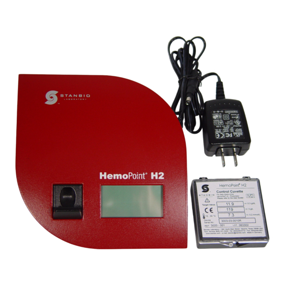
Set up 3. Set up Unpacking the analyzer ® Before you set up the HemoPoint H2 analyzer, first check that all the items are present and undamaged (see Illustration 1). Illustration 1: (1) HemoPoint H2 analyzer, (1) AC power adaptor and (1) control cuvette. ®... -
Page 13: Setting Up The Analyzer
® Why Register your HemoPoint Returning the completed Warranty Registration Card will activate your warranty and allow EKF Diagnostics to provide you with the latest product updates and improvements. Even easier – Go to www.stanbio.com/warranty.php and ® register your HemoPoint... -
Page 14: Switching The Analyzer On And Off
Set up Place the analyzer on a level counter adjacent to a power socket. Make sure there is enough room for the cuvette holder to be freely accessible. Illustration 2: Setting up the analyzer. Switching the analyzer on and off 3.3.1 Using for the first time Allow the analyzer to reach room temperature! -
Page 15: To Operate Using The Power Adaptor
Set up plugged into an electrical socket until the battery is completely charged. This procedure is necessary in order for the capacity of the battery to be checked and the charge indicator to function correctly. Further information on this can be found in Section 6.2 “Charging and care of the battery”. - Page 16 Set up Please be patient after plugging the analyzer into the electrical socket. It may be 4 or 5 seconds before anything appears on the display. This does not indicate a fault but is related to various initialization steps within the analyzer. Following this initialization phase, the display illuminates and a welcome screen appears briefly, after which the instrument is ready to operate.
-
Page 17: Battery Operation
Set up You can find tips on this in Sections 4 “Sampling and Testing Procedure”, 5.2 “Memory (data storage) and 5.3 “Menu functions”. If the analyzer is not in use for some time, it switches into the energy-saving, Stand-by mode (see Section 3.3.4 “Stand-by mode”). -
Page 18: Displays And Symbols In The Ready Mode
Set up • Touch the Touchscreen • Open or close the cuvette holder • Plug the analyzer into an electrical power supply 3.3.5 Displays and symbols in the ready mode Illustration 6: Display in ready mode (Open Holder). HemoPoint H2 User Manual ®... -
Page 19: Sampling And Testing Procedure
Sampling and testing procedure 4. Sampling and testing procedure Taking a sample 4.1.1 Notes on using the microcuvette optical eye ® Illustration 7: n•x•t microcuvette The microcuvette is the most sensitive component in the ® HemoPoint H2 system. It is therefore necessary to handle the cuvette carefully, paying particular attention to the following conditions: 1. -
Page 20: Taking A Sample Of Capillary Blood
Sampling and testing procedure Pay attention to the following notes, to preserve the integrity of the cuvettes: • Store the cuvettes only in the original container and at room temperature (59-86°F / 15-30°C). • Only remove one cuvette at a time from the container and WARNING! then immediately close the lid. - Page 21 Sampling and testing procedure Illustration 8: Preparing to take a blood sample. 2. Make sure that your patient is sitting comfortably. There should be good blood circulation in the hand from which you wish to take blood, i.e. it should be warm and relaxed.
- Page 22 Sampling and testing procedure Only use the middle or ring finger. The patient should not be wearing a ring on the finger used for sampling. Illustration 10: Disinfecting the puncture site. 4. Disinfect the puncture site and allow to dry. Illustration 11: Sticking the finger.
- Page 23 Sampling and testing procedure Illustration 12: Blotting the first drop of blood. 6. Blot away the first drop of blood then, if necessary, press gently once again to get a drop of blood which is large enough to fill the cuvette completely. Avoid “milking”. (For additional information about obtaining a capillary blood sample, read the latest CLSI guideline.
-
Page 24: Taking A Sample Of Venous Or Arterial Blood
Sampling and testing procedure Ensure that the cuvette cavity is completely filled and free of air bubbles. DO NOT try and top-off cuvette if not filled completely. Repeat the process with a new drop of blood and a new cuvette. WARNING! Illustration 14: Removing excess blood. - Page 25 Sampling and testing procedure 2. Mix the sample well (i.e. by a mechanical rotator or by inverting by hand). 3. Take out a microcuvette from the container and immediately close the lid. Please note Section 4.1.1 “Notes on using the microcuvette”. 4.
-
Page 26: Performing The Test
Sampling and testing procedure The cuvette sample can now be tested immediately or within 10 minutes. DO NOT read cuvette after 10 minutes. For further steps, please read Section 4.2 “Performing the test”. Performing the test (“Hgb limit” mode ON with the “Hematocrit” mode ON) Illustration 16: Opening the cuvette holder. - Page 27 Sampling and testing procedure The instrument will check the optical performance of the measuring system. This process takes approx. 1 – 2 seconds. Please release the cuvette holder and do not touch it again until the process is finished and an audible signal (beep) occurs. 2.
- Page 28 Sampling and testing procedure Illustration 20: Inserting the cuvette. 3. Insert the appropriate patient microcuvette (example, Male) into the cuvette holder as shown in Illustration 20, making sure the microcuvette is properly inserted into the holder. 4. Push gently on the cuvette holder and it will close automatically.
- Page 29 Sampling and testing procedure Illustration 21: Display during the testing cycle. testing time varies according hemoglobin concentration and can take approximately 30 – 60 seconds. Patient Types: M … Male, F ... Female, C ... Child Symbols for exceeding Hgb-limits: H …...
-
Page 30: Quality Control
H2 AutoCheck performs an internal check of the analyzer’s optic system every time the cuvette holder is opened. If regulatory quality control checks are required, the quality control check should be performed using EKF Diagnostics liquid controls. 4.3.2 Blank reading... -
Page 31: Control Cuvette
Sampling and testing procedure Always carry out a blank reading whenever you have removed the cuvette holder (i.e., cleaning, replacing with a new cuvette holder). A blank reading can be performed as follows: 1. Open the cuvette holder completely. The text in the display reads “Add Cuvette”. 2. - Page 32 Sampling and testing procedure instrument with which it is delivered, i.e. the Hgb value stated on the storage box label is only valid for that one analyzer, and could lead to completely different results on another analyzer. ® If you have several HemoPoint H2 analyzers, keep track of each control cuvette for each analyzer.
-
Page 33: External Quality Control
3 x Hgb control-high. Instructions for ordering can be found in Section 10.1 “Replacement parts and consumer materials”. There are a variety of hemoglobin controls on the market today. EKF Diagnostics only recommends the use of the HemoPoint ® Hemoglobin Controls,... -
Page 34: Further Functions
Further functions 5. Further functions Touchscreen 5.1.1 General The analyzer has been equipped with a touchscreen. The touch sensitive surface is divided into various individual segments. According to the current operating mode, these segments can be defined as operating buttons. Illustration 24: Divided touchscreen. -
Page 35: Meaning Of The Buttons / Navigation
Further functions 5.1.2 Meaning of the buttons / Navigation Software button, calls up appropriate function Fu n c t io n such as Memory or Menu. “UP” button, selects the next higher listed item or increases the numerical value. “DOWN” button, selects the next lower listed item or decreases the numerical value. - Page 36 Further functions Illustration 26: Display screen, data storage. The entry displayed is the most recent result. Press this button to display preceding results until you reach the first entry on the list. Press this button to display successive results, until you reach the last entry on the list.
-
Page 37: Printing Out Results
Further functions If the estimated Hematocrit mode has been activated the hematocrit result will be displayed as well (see Section 5.3.8.1 “Hematocrit mode”). 5.2.2 Printing out results In order to print out from memory (data storage) you must have a printer connected. -
Page 38: Menu Functions
Further functions • Confirm the selection with , to delete the ES C data storage, otherwise press , in order not to delete. After deleting, the instrument changes back again to display memory (data storage) – “Empty”. Menu functions The analyzer has various possible settings that can be accessed through the menu function. -
Page 39: Information About The Analyzer
Further functions Press this button to scroll up to desired menu entry. Press this button to scroll down to desired menu entry. Press this button to select the next higher ES C menu level, or to leave the menu. Press this button to select the next lower menu level, to adjust settings, or to display information. -
Page 40: Connect
= 1 and n = 0 (factory defaults) the function is not active The correlation can only be enabled by authorized personnel on special request. Contact EKF Diagnostics’ Technical Service Department for additional information. - SPN - The current Service Process Number, needed by Servicing 5.3.2... -
Page 41: Setting The Time
Further functions Press this button to reject the entry and to ES C leave the adjustment. Press this button to confirm the current setting and to access the next entry. After entering the last value, the settings are stored and you leave the adjustment menu. -
Page 42: Hgb Mode And Limits
Further functions You can select the following units: • mmol/L • g/dL (default) • Select the appropriate entry using the arrow buttons. ES C Press this button to reject the selection. Press this button to confirm the selection. 5.3.6 Hgb mode and limits The function of enabling the Hgb mode and setting the limits can be found under “Menu”, sub-menu “Hgb limits”. -
Page 43: Settings
Further functions Please be very careful when setting the contrast. At certain temperatures you can no longer read anything on the display under certain conditions with some contrast settings. Should you accidentally store these settings by pressing the OK button, the WARNING! instrument must be reset. -
Page 44: Setting Time Format
Further functions 5.3.8.3 Setting time format Under “Menu”, sub-menu “Settings”, sub-menu “Time Format” the output format of the time can be set. This affects the output of data records in the memory (data storage) and the printout of the results. The following settings are supported: •... -
Page 45: Setting The Print Mode
Further functions 5.3.9.2 Setting the print mode To print-out test result(s) and result(s) from the memory (data storage), the HemoPoint H2 supports different print modes: ® • • Standard-Print Mode • Expanded-Print Mode (default) Under “Menu”, sub-menu “Options”, sub-menu “Print Mode” the mode of print can be set. -
Page 46: Hgb Limit Mode (On), Hematocrit (On)
Further functions 5.4.2 Hgb limit mode (On), Hematocrit (On) No. Date Time -------------------------------------------------------------- 1. 01/01/09 12:03pm 15.0 g/dL F 44% 2. 01/01/09 12:03pm 13.2 g/dL F 39% Expanded print mode 5.5.1 Header (Example) Stanbio Laboratory www.stanbio.com Version…: X.XX.x Serial No.: 3008-09-0001 Cust.Service: (866) 782-6246 Tech.Service: (800) 531-5535 Printed one time a day, after changing the print mode or after... -
Page 47: Setting The Backlight Mode
Further functions signals as well as the signals that sound at the end of the current test. 5.5.2.2 Setting the backlight mode Under “Menu”, sub-menu “Options”, sub-menu “Backlight” the backlight can be switched ON or OFF when under battery operation. If turned ON the backlight is temporarily switched on for all entries and actions. -
Page 48: Broadcast
5.5.3 Information on contacting us Information on how to contact EKF Diagnostics if you need further help or if you wish to place an order is found under “Menu”, sub- menu “Contact”. This information can also be found in Section 10.2 “Further information”. -
Page 49: Connecting To A Pc
Further functions Only instruments specifically intended for the purpose should be connected to this interface socket, using the appropriate connecting cable. To avoid short circuits, keep sharp metallic WARNING! objects away from the sockets. 5.6.1 Connecting to a PC To connect the HemoPoint H2 analyzer to a PC a special PC ®... -
Page 50: Connecting The Printer Cable
HemoPoint H2 or may be purchased separately from an ® authorized EKF Diagnostics distributor. Please only use the cable intended for this purpose, otherwise both the analyzer and the printer may be seriously damaged. WARNING! -
Page 51: Maintenance
Maintenance 6. Maintenance Cleaning and disinfection of the instrument 6.1.1 Housing and touchscreen It is essential to follow the instructions in Section 1.3 “Safety notes”. Disconnect the power adaptor from the electrical connection before proceeding. WARNING! Cleaning the housing and touchscreen is best accomplished with a lint-free cloth, lightly dampened with clean water. -
Page 52: Optical Unit
Maintenance Illustration 34: Removing the cuvette holder. The cuvette holder can now be cleaned with a mild soap solution. For disinfection, standard solvent-free preparations can be used. To replace the cuvette holder, simply push it in the correct position into the opening in the housing until it engages. Please wait until the cuvette holder is completely dry before replacing it. -
Page 53: Power Adaptor
® optics cleaner is recommended. The Optics Cleaner can be obtained through an authorized EKF Diagnostics distributor. Please follow the instructions for use that can be found in the package insert that comes with the Cleaner or go online to www.stanbio.com Tech Support, “Routine Cleaning of the... -
Page 54: Charging Procedure
Maintenance capacity over time. Frequent partial discharging and re-charging accelerates this process. By observing a few “golden rules” you can considerably influence the life span of the battery: 6.2.1 Charging procedure To maintain the battery’s full capacity, the battery should always be discharged as completely as possible before being recharged again. -
Page 55: Self Discharge
Section 7 “Troubleshooting”. If you require assistance, contact EKF Diagnostics’ technical service department (see Section 10.2 “Further information”). Proper disposal It is the responsibility of the user to arrange proper disposal of the individual components. -
Page 56: Troubleshooting
Troubleshooting 7. Troubleshooting Before you call EKF Diagnostics’ technical service department or send the instrument in for repair, please try to define or solve the problem with the help of this section. Care! Danger of fatal electric shock! It is essential to follow the instructions in Section 1.3 “Safety notes”. - Page 57 Troubleshooting - Instrument plug not connected. - Wrong power adaptor. - Defective power adaptor. ->Contact EKF Diagnostics Technical Support. Error message Disconnect the wrong adaptor immediately “Wrong power supply" and connect with the correct HemoPoint ® adaptor. Error message When operated with the power adaptor: "User error, voltage too...
- Page 58 Error message - Internal problem of instrument; operation not "CRC ROM" possible. "CRC RAM" ->Contact EKF Diagnostics Technical Support. "CRC EEProm" Error message - Control cuvette or microcuvette in the closed "Defective electronics" cuvette holder when the instrument is switched on;...
- Page 59 Troubleshooting 6.1.3 “Optical unit”). - Internal problem of instrument; operation not possible. ->Contact EKF Diagnostics Technical Support. Display screen is hard to read. Display contrast setting Reset the display contrast (see Section 5.3.6 “ is unsuitable. Setting the display contrast”).
- Page 60 Troubleshooting Display texts are not shown in your language. Language is set Set your language incorrectly. (see Section 5.3.7.1 “Setting the language”). Time displayed is incorrect. Time is set incorrectly. Reset the time (see Section 5.3.3 “Setting the time”). Date shown in the printout or data storage is incorrect or will not be displayed as expected.
-
Page 61: Resetting Of The Analyzer
Troubleshooting Resetting of the analyzer The “Reset” serves to transfer the analyzer to its default settings, without changing user-specific settings significantly. The settings for contrast, date and time are lost. The reset button can be found on the underside of the analyzer. Reset button Illustration 37: Location of the reset button. -
Page 62: Technical Data
Technical data 8. Technical data HemoPoint H2 analyzer ® Measuring Optical absorption photometry. procedure Dual-Color-LED 570 / 880 nm Source 570 ± 5 nm Dominant wavelength: wavelength of 880 ± 10 nm wavelength: source 15 ± 3 nm Spectral half value wavelength: width of the source wavelength:... -
Page 63: Icrocuvette
Technical data Weight 1.3 lbs. AC Power adaptor: Power supply Input: 100- 250 V AC / 50-60Hz Output: 6 VDC Integrated battery: Voltage: 3.6 V Capacity: 2000 mAh (ca. 100 h operation time) Power maximal: typically: 1.2 W minimal: 30 mW Interface Printer (RS 232 C) Room temperature (15 –... -
Page 64: Reference Range
Reference Range 9. Reference range Normal range Different blood hemoglobin values have been reported in the (1,2,3,4) literature Adult Males: 13.0 – 18.0 g/dL Adult Females: 11.0 – 16.0 g/dL Children (2 yrs to teenage): 11.0 – 16.0 g/dL Infants (post-natal) 10.0 –... -
Page 65: Appendix
Appendix 10. Appendix 10.1 Replacement parts and consumer materials Reference No. Description Ordering ® 3015-100 HemoPoint H2 n•x•t 1 kit Microcuvettes ® 2 Containers @ 50 cuvettes each (100 tests) ® 3015-200 HemoPoint H2 n•x•t Microcuvettes 1 kit ® 4 Containers @ 50 cuvettes each (200 tests) ®... -
Page 66: Further Information
If you have any questions over and above this user manual, we would be pleased to help. Here is all the important contact information: Main address: EKF Diagnostics Inc. 1261 North Main Street Boerne, Texas 78006 U.S.A. (830) 249-0772 / (866)782-6246... -
Page 67: Index
Index Index disposal · 52 accessories · 9, 45, 52 air bubbles · 21, 22 environmental temperature · 39, 60 backlight · 44 battery · 11, 12, 36, 60 hematocrit battery charging and care · 50, output activation · 41 51, 52 hemoglobin concentration ·... - Page 68 Index moisture · 16 sample material · 59 sample size · 59 sampling procedure · 17, 21 self discharge · 51 service menu · 45 navigation · 32 setting up · 9, 10, 11 stand-by · 14, 44 storage, microcuvette · 60 symbols danger symbol ·...
- Page 69 Index HemoPoint H2 User Manual ®...
- Page 70 Stanbio 1261 North Main Street, Boerne, TX 78006 Email: sales2@ekfdiagnostics.com +1 (830) 249-0772 Fax +1 (830) 249-0851 www.ekfusa.com 3072E-001 3072E-001.01 Diagnostics for life...
Need help?
Do you have a question about the Stanbio HemoPoint H2 and is the answer not in the manual?
Questions and answers