Honeywell VisionPRO Series Installation Manual
With redlink
Hide thumbs
Also See for VisionPRO Series:
- User manual (132 pages) ,
- Installation manual (25 pages) ,
- User manual (60 pages)
Advertisement
Wired Directly to Equipment
Dual Powered - C Wire or Battery
(C wire or Wire Saver required to use RedLINK accessories)
RedLINK to Equipment Interface Module
2 Wires for Power or
Battery Only (no wires)
RedLINK to TrueZONE Wireless Adapter
2 Wires for Power or
Battery Only (no wires)
VisionPRO
Installation Guide
OR
TM
OR
TM
®
Series with RedLINK
™
TM
M37817
Advertisement
Table of Contents

Related Manuals for Honeywell VisionPRO Series


Summary of Contents for Honeywell VisionPRO Series
- Page 1 ® ™ VisionPRO Series with RedLINK Installation Guide Wired Directly to Equipment Dual Powered - C Wire or Battery (C wire or Wire Saver required to use RedLINK accessories) RedLINK to Equipment Interface Module 2 Wires for Power or Battery Only (no wires) RedLINK to TrueZONE Wireless Adapter 2 Wires for Power or Battery Only (no wires)
-
Page 2: Getting Started
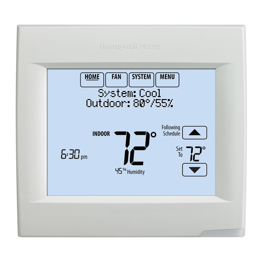
Reference to key features Current display. Underlined label signifies the current display. Mode control buttons. Use to change settings for Fan or System Heat/Cool. Menu. Select options to: set schedules, view equipment status, change IAQ settings, access installer options*, etc. Current status. -
Page 3: Installing The Thermostat
Installing the thermostat Thermostat Button NOTE: For best RedLINK performance, mount thermostats at least 2 feet apart. 1.1 Separate wallplate from thermostat. If your thermostat has a button Wallplate along the top of the wallplate, press (back view) button on top and pull to remove the wallplate as shown. - Page 4 1.4 Wire the thermostat. CONVENTIONAL Is the thermostat wired directly to the equipment? • If the thermostat is wired directly to the equipment: a Refer to the table and wiring diagrams on the next page. b Turn on 24VAC NOW. 24VAC (C wire) is required to HEAT PUMP connect RedLINK accessories.
- Page 5 Terminal Designations Conventional System Heat Pump Terminal Description Terminal Description Common wire from secondary side of Common wire from secondary side of cooling transformer (if 2 transformers). cooling transformer. Cooling power. Cooling power. Heating power. Heating power. Heat Stage 1 Changeover valve for heat pumps.
-
Page 6: Performing Initial Setup
Powering optional RedLINK accessories 2.1 Install batteries in RedLINK NOTE: If the thermostat is wired accessories. directly to the equipment, 24VAC (C • Portable Comfort Control wire) is required to connect RedLINK • Wireless Outdoor Sensor* accessories. Turn on 24VAC before performing initial setup in Step 3. - Page 7 3.3 Connect each RedLINK accessory. NOTE: Accessories must be at least 2 feet away from the thermostat during Press Connect on the linking process. New Accessories. 3.3a While the Press Connect message is displayed (listening mode), press and quickly release the CONNECT button on each new RedLINK accessory.
-
Page 8: Finding Your Password (Date Code)
Finding your password (Date Code) • To add or remove RedLINK accessories Thermostat (back view) • To make changes to Installer Setup • To perform an Installer Test RoHs Compliant Finding your password Conformité RoHs Assembled in Mexico Assemblé au Mexique You can find the date code RoHs Compliant Conformité... - Page 9 5 Select Device. The screen displays “Press Connect on New Accessories.” The Add Device thermostat is now in listening mode. Connected Devices NOTE: Accessories must be at least 2 feet away from the thermostat during MCR33981 the linking process. the CONNECT Press and quickly release button on each new RedLINK Press Connect on...
- Page 10 Log and Interaction Log) to a microSD card - then view them on your computer. Also use the microSD card to upgrade the thermostat software. Loading Dealer Information and New Thermostat Software: 1 Visit http://thermostatsetup.honeywell.com Computer to enter your dealer information or load new thermostat software.
-
Page 11: Electrical Ratings
Specifications and replacement parts Operating Ambient Temperature Thermostat: 32 to 120° F (0 to 48.9° C) Portable Comfort Control: 32 to 120° F (0 to 48.9° C) Wireless Outdoor Sensor: -40 to 140° F (-40 to 60° C) Wireless Indoor Sensor: 0 to 120° F (-17.8 to 48.9° C) -For Optimal Battery Life: 35 to 114°... - Page 12 69-2760—07 M.S. Rev. 04-19 | Printed in United States ©2019 Resideo Technologies, Inc. This product is manufactured by Resideo Technologies, Inc., Golden Valley, MN, 1-855-733-5465. 69-2760-07 The Honeywell Home trademark is used under license from Honeywell International Inc. All rights reserved.
Need help?
Do you have a question about the VisionPRO Series and is the answer not in the manual?
Questions and answers