Table of Contents
Advertisement
Quick Links
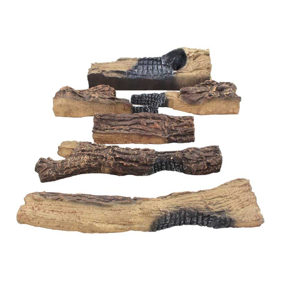
Log Set Assembly: LOGS-6000GL
Models: 6000GL-IPI-R, 6000GL-IPI-S
If the gas logs have been factory installed they
should not need to be positioned. If the logs have
been packaged separately, refer to the following
instructions.
STEP 1.
CAUTION: Logs are fragile! Carefully remove
the logs, grate and supporting cardboard from
the inside of the fi replace See Figure 1.
STEP 2.
Place the metal grate on top of the burner.
Position the legs of the grate into the forward
set of indentations in the burner top. The grate
should not cover any ports in the burner.
Figure 2. Front View
STEP 3. Log #1 (SRV2102-010):
over the brass orifi ce located behind the main burner. The log should be parallel to back refractory.
2 2
Figure 4. Front View
STEP 4. Log #2 (SRV2102-101):
over the left metal tab sticking up out of the top of log #1. The left end of this log sits on the burner surface.
1 1
Log #1 is the back burning log. The air shutter in the end of the burner tube goes
Place log #2 on top of log #1. The bottom side of this log has a slot in it that goes
Heat & Glo • 6000GL • 2102-910 Rev. C • 8/06
2 2
Figure 1
Figure 3. Top View
Figure 5. Top View
LOG PLACEMENT
INSTRUCTIONS
5 5
1 1
3 3
4 4
1 1
HUMP
HUMP
2 2
6 6
1
Advertisement
Table of Contents

Related Manuals for Heat & Glo LOGS-6000GL


Summary of Contents for Heat & Glo LOGS-6000GL
- Page 1 Log Set Assembly: LOGS-6000GL LOG PLACEMENT Models: 6000GL-IPI-R, 6000GL-IPI-S INSTRUCTIONS If the gas logs have been factory installed they should not need to be positioned. If the logs have been packaged separately, refer to the following instructions. STEP 1. CAUTION: Logs are fragile! Carefully remove the logs, grate and supporting cardboard from the inside of the fi...
- Page 2 Figure 6. Front View Figure 7. Top View STEP 5. Log #3 (SRV2102-105): Place log #3 on top of the burner surface in front of the hump. The bottom of the log is contoured to match some of the burner surface features. Slide it back against the hump. The “V” shaped notch in the front bottom of the log rests into the second from the left grate tine.
- Page 3 Figure 12. Front View Figure 17. Top View STEP 8. Log #6 (SRV2102-102): Place log #6 on top of log #5 and log #4. There is a fl at spot molded into the top of log #4 and log #5. Place the log so the long end of the “Y” rests on log #5 and the short end of the log rests on log #4. The end of the log rests on the burner surface.
Need help?
Do you have a question about the LOGS-6000GL and is the answer not in the manual?
Questions and answers