Table of Contents
Advertisement
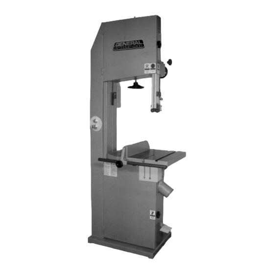
Heavy-duty one-piece frame, designed for
added stability, requires no further
assembly.
Precision-balanced, rubber laminated,
cast-iron wheels, mounted on two
heavy-duty ball bearings.
Large, ribbed cast-iron table with heavy-
duty one-piece trunnion for 0 - 45° tilting,
for bevel cuts.
Convenient blade tension adjustment
hand wheel.
A tension scale allows the operator to
adjust the tension for different blade
widths.
Foot Brake for quick blade stoppage after
machine shut-off.
4" dust collection port for easy hookup to
a dust collector.
Powerful totally enclosed fan cooled
(T.E.F.C.) industrial motor.
Magnetic safety switch with emergency
stop button for added safety.
Tri-Axis bearing guides.
WHEEL SIZE
18" (450 MM)
WHEEL SPEED
980 RPM
- #90-270
1010 RPM
- #90-270 HD
WIDTH OF WHEEL
1 1⁄8" (28.5 MM)
MIN/MAX BLADE WIDTH
1⁄4" TO 1" (6.3 TO 25.4 MM)
BLADE LENGTH
153" (3886 MM)
- #90-270
168 1⁄2" (4280 MM)
- #90-270 HD
BLADE SPEED
4460 FPM (1338 MPM)
- #90-270
4700 FPM (1410 MPM)
- #90-270 HD
MAXIMUM DEPTH OF CUT
12" (305 MM)
- #90-270
18" (457 MM)
- #90-270 HD
MAXIMUM WIDTH OF CUT
17 1⁄4" (438 MM)
TABLE SIZE
24" X 19 1⁄2" (610 X 500 MM)
TABLE TILT
0° TO 45° (OUT)
TABLE HEIGHT
35 1⁄2" (902 MM)
MOTOR
- #90-270
M1 - 3 HP , 220 V, 1 PH, 19 A
M2 - 3 HP , 220/440 V, 3 PH, 8/4.6 A
M3 - 3 HP , 600 V, 3 PH, 2.9 A
MOTOR
- #90-270HD
M1 - 5 HP , 220 V, 1 PH, 23 A
M2 - 5 HP , 220/440 V, 3 PH, 13.3/7.6 A
M3 - 5 HP , 600 V, 3 PH, 4.8 A
WEIGHT
616 LBS (280 KG)
- #90-270
710 LBS (323 KG)
- #90-270 HD
REVISION 1 - FEB 04/08
© COPYRIGHT GENERAL INTERNATIONAL 02/2008
Advertisement
Table of Contents

Related Manuals for General 90-270


Summary of Contents for General 90-270
- Page 1 M2 - 5 HP , 220/440 V, 3 PH, 13.3/7.6 A M3 - 5 HP , 600 V, 3 PH, 4.8 A WEIGHT 616 LBS (280 KG) - #90-270 710 LBS (323 KG) - #90-270 HD REVISION 1 - FEB 04/08 © COPYRIGHT GENERAL INTERNATIONAL 02/2008...
- Page 2 Because of our commit- ment to quality and customer satisfaction, General® International agrees to repair or replace, within a period of 24 months from date of purchase, any genuine part or parts which, upon examination, prove to be defective in work- manship or material.
- Page 3 To help ensure safe operation, please take a moment to learn the machine’s applications and limita- tions, as well as potential hazards. General® International disclaims any real or implied warranty and hold itself harmless for any injury that may result from the improper use of it’s equipment.
- Page 4 E E L L E E C C T T R R I I C C A A L L R R E E Q Q U U I I R R E E M M E E N N T T S S NOTE: VOLTAGE REQUIREMENTS AND AMPERAGE DRAW FOR M2 &...
- Page 5 18” WOOD CUTTING BANDSAW 90-270 or 90-270HD IDENTIFICATION OF MAIN PARTS AND COMPONENTS FRONT VIEW REAR VIEW UPPER WHEEL TENSION ADJUSTMENT HAND WHEEL FENCE BLADE GUARD LOCK KNOB LOWER WHEEL UPPER BLADE GUIDES AND SUPPORT BLADE GUARD ADJUSTMENT BEARING ASSEMBLY...
- Page 6 To limit the risk of serious injury or damage to the machine, any equipment used to lift this machine (hoist or fork- lift) should have a rated capacity in excess of 616 lbs (280 kg) for model 90-270 and of 671 lbs (305 kg) for model 90-270HD.
- Page 7 To prevent rust, apply a light coating of paste wax or use regular applications of any after-market surface protec- tant or rust inhibitor such as General International “Top Saver” item #GC-010. Tip: With a screw driver, push a solvent-saturated rag into the T-slot to remove the grease.
- Page 8 ASSEMBLY INSTRUCTIONS For your convenience this bandsaw is shipped from the factory partially assembled and requires only minimal assembly and set up before being put into service. Serious personal injury could occur if you connect the machine to the power source before you have completed the installation and assembly steps.
- Page 9 INSTALLING THE TABLE This bandsaw table is heavy. Do not over-exert. The help of an assistant will be needed for the following step. Note: Make sure that both table tilt trunnion grooves align in the trunnion bracket 90° CW Put the flat washer down on the table tilt trunnion Guide the gap between the rail and the edge of then slip the table tilt trunnion bolt through the hole in the table over the saw blade...
- Page 10 This 18" wood cutting bandsaw is supplied with a 1/2" wide general purpose blade and is designed to accommo- date blade widths from 1/4" to 1". Ideal blade length for the model 90-270 is 153" (3886 mm) and ideal blade length for the 90-270HD is 168 1/2"...
- Page 11 BASIC ADJUSTMENTS AND CONTROLS CONNECTING TO A POWER SOURCE SWITCH Contact a qualified electrician for the installation of a power plug and cord for connecting the band- saw to a power source. To avoid risk of shock or fire do not operate the unit with a damaged power cord or plug. Replace dam- aged cord or plug immediately.
- Page 12 RECOMMENDED ADJUSTMENTS TILTING THE TABLE The table can be tilted to any angle from 0 to 45 degrees to the right, to allow for any type of bevel (or angle) cut- ting. The table tilt angle indicator is located on the back of the trunnion. To tilt the table: Before making any adjustments, make sure that the switch is in the “OFF”...
- Page 13 With the table set to 90 degree and the stop bolt at Adjust the table angle manually until it is set to the correct height, make sure the angle indicator 90 degrees by making sure there is no space bet- pointer is set to read 0 degrees .
- Page 14 Ask your local tool dealer for suggestions for bandsaw blades (153" for model 90-270 and 168.5" for model 90-270HD) in 1/4" to 1" widths, based on what is available in your area.
- Page 15 ADJUSTING BLADE TENSION Determining ideal blade tension is somewhat subjective. It is learned through practice and experience and is somewhat dependant on personal preference and individual work habits. A properly tensioned blade is critical to obtaining maximum performance from any bandsaw. A properly tensioned blade will last longer and be much less likely to break prematurely.
- Page 16 BLADE TRACKING ADJUSTMENTS 3 MM - 1/16" Ideally, the blade should stay relatively centered on both the upper and lower wheels (Fig. 6). Due to natural variations in castings, blade thickness or density and tire wear, absolute perfect centering align- ment is rarely attainable.
- Page 17 Note: The upper and lower wheels are factory set to allow for easy and optimal blade tracking adjustments using the primary blade tracking adjustment knob, which adjusts the angle of tilt of the upper wheel. In extremely rare cases, if acceptable blade tracking cannot be attained through the primary adjustment it may eventually become necessary to make minor adjustments to the angle of tilt of the lower wheel.
- Page 18 POSITIONING THE UPPER/LOWER BLADE GUIDES AND SUPPORT BEARING ASSEMBLIES The upper/lower blade guides and support bearing are both assembled as one unit which can be moved back or forward. To prevent damage to the blade, the blade guide bearings must remain behind the blade teeth during operation.
- Page 19 Turn off the bandsaw and unplug the power cord.
- Page 20 Make sure all the blade guards are in place. Make sure the bandsaw table and work area in general are clean and free of sawdust and debris. These steps should always be followed when any adjustment is performed, the blade is changed, or periodically as vibra- tion and normal wear and tear on the machine could throw these parts out of alignment.
- Page 21 TO STOP THE MACHINE 1. Press the red “OFF” button at the front of the frame of the bandsaw to stop the motor. 2. Apply the foot brake to immobilize the blade. 3. Turn your dust collector off. INSTALLING/USING THE RIP FENCE For more precise straight line cuts there is a removable rip fence that can be installed on the rail of the bandsaw table.
- Page 22 CUTTING CURVES • When cutting curves, carefully turn the workpiece so the blade follows without twisting. If the curve is so sharp that you repeatedly back up and cut new kerf, use a narrower blade, or a blade with more set (teeth further apart). When a blade has more set, the workpiece turns easier but the cut is rougher.
- Page 23 5. To prevent rust and so that the wood slides easily while cutting , apply a light coating of paste wax or use regu- lar applications of any after-market surface protectant or rust inhibitor such as General International “Top Saver”...
- Page 24 REPLACING LOWER WHEEL MOTOR BELT(S*) *The lower wheel on Model 90-270 is driven by one belt while the lower wheel on Model 90-270HD is driven by two belts The lower wheel is driven by (a) belt (s*) mounted on pulley powered by the motor. The belt(s*) tension s hould be verified upon reception of the machine, then every 6 months.
- Page 25 MOTOR UNDERSIDE VIEW MOTOR HANDLING REMOVING MOTOR # 90-270HD ONLY 90-270 & 90-270HD The motor on model 90-270HD is very heavy. Do not Loosen the nut under the motor support plate , and over-exert. The help of at least one assistant will be remove the bolt .
- Page 26 We offer a large variety of products to help you increase productivity, accuracy and safety when using your bandsaw. Here’s a small sam- pling of accessories available from your local General International dealer. For a complete list, visit our website at www.general.ca. Dust Collector...
- Page 27 FRAME ASSEMBLY 53-1 38 * 11 * 23 * *Not identical between both models (note: correct # based on model before ordering.)
- Page 28 MOTOR (FOR MODEL 90-270) 90270HD-09 MOTOR (FOR MODEL 90-270HD) 90270-10 8 X 8 X 45 90270-11 MOTOR PULLEY (FOR MODEL 90-270) 2-1/2"A1 X 24 X 8 90270HD-11 MOTOR PULLEY (FOR MODEL 90-270HD) 2-1/2"A1 X 28 90270-12 MOTOR PULLEY FIXING SCREW 5/16-18 X 1/2"...
- Page 30 PARTS LIST 90-270 PART N0. REF. N0. DESCRIPTION SPECIFICATION 90270-54 SAW BLADE (FOR MODEL 90-270) 1/2 " X 3886 MM 90270HD-54 SAW BLADE (FOR MODEL 90-270HD) 1/2 " X 4280 MM 90270-55 UPPER WHEEL 90270-56 UPPER WHEEL SHAFT 90270-57 BEARING...
- Page 31 TABLE ASSEMBLY 112 * 122 * 135 137 *Not identical between both models (note: correct # based on model before ordering.)
- Page 32 HEX HEAD BOLT 5/16-18 X 1" 90270-110 LOCK WASHER 5/16" 90270-111 LOCK KNOB 3/8" X 60 90270-112 BLADE GUARD SHAFT (FOR MODEL 90-270) 90270HD-112 112 BLADE GUARD SHAFT (FOR MODEL 90-270HD) 30 X 690MM 90270-113 C RING S-30 90270-114 PINION...
- Page 33 GUARDS 1 6 5 *Not identical between both models (note: correct # based on model before ordering.)
- Page 34 PARTS LIST 90-270 PART N0. REF. N0. DESCRIPTION SPECIFICATION 90270-143 WING NUT 1/4" 90270-144 FLAT WASHER 90270-145 LOWER GUARD 90270-146 LOCK WASHER 1/4" 90270-147 HEX HEAD BOLT 1/4 X 1/2 90270HD-148 148 HEX HEAD BOLT (MODEL 90-270HD ONLY) 1/4 X 1/2...
- Page 35 NOTES...
- Page 36 Fax : (514) 326-5565 Parts & Service Fax : (514) 326-5555 Order Desk orderdesk@general.ca www.general.ca IMPORTANT: When ordering replacement parts, always give the model number, serial number of the machine and part number. Also a brief description of each item and quantity...
Need help?
Do you have a question about the 90-270 and is the answer not in the manual?
Questions and answers