Table of Contents
Advertisement
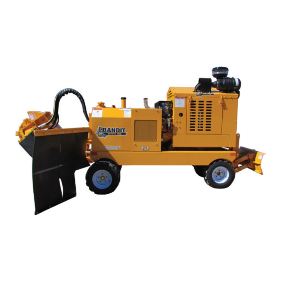
OPERATING & PARTS MANUAL
MODEL 2890SP / 2900T
Model No: __________________________
Serial No: __________________________
DEALER:
Name: _____________________________
Address: ___________________________
City/State: __________________________
Phone No: __________________________
Delivery Date: _______________________
Engine Make: _______________________
Serial No: __________________________
Clutch Make: ________________________
Model: ___________ S/N _____________
Copyright 12/17
ATTENTION:
Depending on what replacement parts you are ordering, we will need the following information:
STUMP GRINDER COMPONENTS
ENGINE COMPONENTS
Serial Number
Brand
Model Number of Stump Grinder
Engine Serial Number
Engine Model Number
MANUFACTURED BY BANDIT INDUSTRIES, INC
PHONE:
989
561-2270
(
)
PHONE:
800
952-0178 IN USA
(
)
FAX:
989
561-2273 ~ SALES DEPT.
(
)
FAX:
989
561-2962 ~ PARTS/SERVICE
(
)
WEBSITE:
www.banditchippers.com
6750 Millbrook Rd. • Remus, MI 49340 • 1-989-561-2270
Advertisement
Table of Contents
Troubleshooting

Related Manuals for Bandit 2890SP


Summary of Contents for Bandit 2890SP
- Page 1 OPERATING & PARTS MANUAL MODEL 2890SP / 2900T Model No: __________________________ Serial No: __________________________ DEALER: Name: _____________________________ Address: ___________________________ City/State: __________________________ Phone No: __________________________ Delivery Date: _______________________ Engine Make: _______________________ Serial No: __________________________ Clutch Make: ________________________ Model: ___________ S/N _____________...
- Page 3 11. _____ The customer has received instruction and fully understands that warranty will not apply if the machine is operated with replacement parts or equipment not manufactured or recommended by Bandit Industries, Inc. 12. _____ The customer has received, been advised, and understands the manuals, and the Safety/Service video supplied with the grinder.
- Page 5 Copyright 4/17 FORM #Q-112 DATE PURCHASE: ______________________ TO BE RETURNED AFTER THIRTY (30) DAYS OF OPERATION MODEL: ________________________________ SERIAL NUMBER: _______________________ Please return to: Customer Data Department 6750 Millbrook Road DEALER NAME: ________________________ Remus, MI 49340 _______________________________________ Phone: (800) 952-0178 in USA Phone: (989) 561-2270 Fax: (989) 561-2273...
-
Page 7: Table Of Contents
MODELS 2890SP/2900T TABLE OF CONTENTS TABLE OF CONTENTS PAGE INTRODUCTION & WARRANTY ............2 SERIAL NUMBER LOCATIONS ............6 SAFETY PROCEDURES ................ 7 EQUIPMENT SPECIFICATIONS ............12 DECALS ....................13 CONTROLS ..................... 19 MACHINE OPERATION ................. 27 TRANSPORTATION PROCEDURES ............ 30 MAINTENANCE .................. -
Page 8: Introduction & Warranty
The purpose of this manual is to provide the user with specifi cations and procedures for the operation, maintenance and repair of this BANDIT product. As with any piece of equipment, safety should always be a constant thought while the machine is being operated, serviced or stored. - Page 9 The warranty validation form must be completed and submitted to Bandit Industries within 10 business days of the purchase of your Bandit machine. Any and all warranty is NULL AND VOID if the Warranty Validation Form is not returned within 10 business days of the original purchase of the machine.
- Page 10 This warranty will not apply if the Bandit product is not operated with replacement parts or equipment not manufactured or recommended by Bandit Industries, Inc. This warranty will not apply if the Bandit product is not operated in a manner recommended by the manufacturer. The following examples would void the warranty: 1.
- Page 11 Manufacturer or our authorized dealer. If an RMA is given to return the failed parts, they must be returned within 10 business days to the respective vendor or Bandit Industries depending on the instructions given. The new parts must be installed and work be complete within 10 business from receiving the parts to receive credit.
-
Page 12: Serial Number Locations
MODELS 2890SP/2900T SERIAL NUMBER LOCATIONS TYPICAL SERIAL NUMBER AND/OR WORK ORDER NUMBER LOCATIONS NOTICE 1. S/N on side of control box 2. W/O # on pivot mount plate The engine information is located on the engine block. Bandit Copyright 12/17... -
Page 13: Safety Procedures
You may obtain additional copies of this Torn or loose clothing is more likely to get caught manual from your Bandit Dealer. in moving machinery parts. Keep such items as long Before operating machine, you must have all hair, shirt sleeves, and shirt tails properly contained. - Page 14 t. from top of tank for diesel engines and 2” (50mm) Most of the nuts used on the Bandit Grinder are from the top of the tank for gasoline engines. self locking. After a nut or bolt has been removed To obtain the most from your machine, for the least fi ...
- Page 15 MODELS 2890SP/2900T SAFETY PROCEDURES SAFETY PROCEDURES DANGER DANGER DO NOT start the engine with the clutch or cutter Never grind materials that might contain wires, wheel engaged. stones, nails, or other metal objects which may damage NOTICE the teeth and become dangerous projectiles. Remove all rocks and stones from stump grinding area.
- Page 16 MODELS 2890SP/2900T SAFETY PROCEDURES SAFETY PROCEDURES WARNING WARNING CLEAN MACHINE OF ALL DEBRIS! DO NOT Sparks can occur if cutter teeth strike rocks, leave this machine unattended until all potential fi re metal, or other hard objects. debrisisremoved,nofi reor s molderingexists,and...
- Page 17 MODELS 2890SP/2900T SAFETY PROCEDURES SAFETY PROCEDURES IF MACHINE IS EQUIPPED WITH A SELF PROPELLED UNDERCARRIAGE Machines equipped with undercarriage tracks are shipped with a manual from the track manufacturer. Refer to it for service, operation, and safety information. WARNING Do not attempt to operate the machine on an ascending or descending slope of more than 25° or 46% or a side slope of more than 17°...
-
Page 18: Equipment Specifications
MODELS 2890SP/2900T EQUIPMENT SPECIFICATIONS EQUIPMENT SPECIFICATIONS Approximate Dimensions & Weights (Dimensions & Weights will vary depending on optional equipment) Model 2890SP Model 2900T Height: 75” (1.9 m) Height: 75” (1.9 m) Length: Length: 162” (4.1 m) 161” (4.1 m) Width: 35”/56”... -
Page 19: Decals
MODELS 2890SP/2900T DECALS DECAL LOCATIONS DANGER DO NOT go near the rotating cutter wheel for any reason. DO NOT go near the cutter wheel while the engine is running or the cutter wheel is coasting to a stop. Contact with a rotating cutter wheel will result in serious bodily injury or death. - Page 20 MODELS 2890SP/2900T DECALS DECAL LOCATIONS - 2890SP Decal locations may vary, these are general locations. 33,34 6,10 2,23,27,30,40 11,15,18,21,22 4,7,35 1,2,9,14,43 11,18 37,41,42 13,32,36 1,3,9,43 6,10 Bandit Copyright 12/17...
- Page 21 SPW-31 Explosion Hazard... SPW-32 ...Tether Cord... 900-8900-34 Basic Safety Decal Kit (Options may require additional decals) 900-8900-62 Bandit Model 2890SP Logo Decal Kit 48. 900-2909-94 RedReflectiveDecal 49. 900-2909-95 AmberReflectiveDecal Some decals are for optional equipment. Decal locations may vary, these are general NOTICE locations.
- Page 22 MODELS 2890SP/2900T DECALS DECAL LOCATIONS - 2900T Decal locations may vary, these are general locations. 2, 4,11,18,26,31,36 28,29, 32,34 21,22 1,3,6,38 14,19,20 4,30,33 7,24 15,16 12,23,27 1,8,35 5,9,31 1,3,6 Bandit Copyright 12/17...
- Page 23 SPW-31 Explosion Hazard... SPW-32 ...Tether Cord... 900-8900-34 Basic Safety Decal Kit (Options may require additional decals) 900-8900-41 Bandit Model 2900T Logo Decal Kit 41. 900-2909-94 RedReflectiveDecal 42. 900-2909-95 AmberReflectiveDecal Some decals are for optional equipment. Decal locations may vary, these are general NOTICE locations.
- Page 24 DECALS DECALS Decals located on your Bandit equipment contain useful information to assist you in operating your equipment safely. Some of the decals on your machine and their location are shown in this section. It is very important that all decals remain in place and in good condition on your machine. Please follow the care and instructions given below: You should use soap and water to keep your decals clean.
-
Page 25: Controls
MODELS 2890SP/2900T CONTROLS MACHINE ORIENTATION REFERENCE R I G Bandit Copyright 12/17... - Page 26 MODELS 2890SP/2900T CONTROLS EMERGENCY STOP (E-STOP) DANGER Avoid moving parts. Keep hands, feet, and clothing away from power driven parts. Keep all guards and shields in place and properly secured. DANGER DO NOT go near the rotating cutter wheel for any reason. DO NOT go near the cutter wheel while the engine is running or the cutter wheel is coasting to a stop.
- Page 27 ENGINE OPERATING SPEEDS NOTICE Refer to the Completion/Check Sheet, that is shipped with the machine for the correct engine rpm. If needed, contact your local dealer or Bandit Industries. Some Current Engine Types Maximum RPM CAT C3.4 / Perkins 854 - 100 Hp 2800 GM 5.7L - 165 Hp...
- Page 28 MODELS 2890SP/2900T CONTROLS CONTROLS - REMOTE Basic Location of Controls and Components LOCATION SHOWN 1. Travel Speed Control 9. Status Light 17. Left Track 2. Swing Speed Control 10. PowerOn/Off 18. Drive Speed 3. Link Light 11. Blade Down / Up 19.
- Page 29 MODELS 2890SP/2900T CONTROLS CONTROL OPERATING PROCEDURES - REMOTE 1. Travel Speed Control: The travel speed controls the rate the machine approaches the stump. To decrease the travel speed, turn the control knob counter-clockwise. 2. Swing Speed Control: The swing speed controls the rate the cutter wheel passes through the stump.
- Page 30 MODELS 2890SP/2900T CONTROLS CONTROLS SWING OUT Basic Location of Controls and Components LOCATION SHOWN Ignition Switch Steer Right / Left Power Display 10. Grading Blade Down / Up Swing Out Lock Pin 11. Cutter Down / Up Travel Speed Control 12.
- Page 31 MODELS 2890SP/2900T CONTROLS CONTROL OPERATING PROCEDURES SWING OUT 1. Ignition Switch: Locationvarieswithdifferentengineoptions. 2. Power Display: Displays engine information: Temperature, RPMs, Tach / Hour Meter, etc. 3. Swing Out Lock Pin: Lock the swing out lock pin into the operating position or the transport position.
- Page 32 To decrease you would push in the knob or turn the handle the opposite way. “Bandit” Lever Lock Cable Throttle System (if equipped): The Bandit throttle system has (2) positions, HIGH and LOW. Engine R.P.M. is controlled by moving the lever from one position to the other.
-
Page 33: Machine Operation
MODELS 2890SP/2900T MACHINE OPERATION MACHINE OPERATION DANGER DO NOT START TO GRIND A STUMP UNLESS YOU ARE COMPLETELY SURE THERE ARE NOT ANY UTILITY LINES IN THE AREA ABOVE OR BELOW THE GROUND LEVEL WHERE YOU ARE GRINDING. ALWAYS CONTACT THE UTILITY LOCATING SERVICE IN YOUR AREA OR LOCAL UTILITY COMPANIES TO MARK UNDERGROUND UTILITY LINES. - Page 34 MODELS 2890SP/2900T MACHINE OPERATION MACHINE OPERATION Position machine at stump with cutter wheel a slight Lower the spinning cutter wheel to the stump and distance away from stump. make a few light passes at the stump to get a feel for the cutting action.
- Page 35 MODELS 2890SP/2900T MACHINE OPERATION MOVING A 2890SP MACHINE WITHOUT POWER NOTICE Use this procedure only when the machine will not start or run to help prevent damage to the hydraulic system. Withthekeyinthe“off ”positionandinyourpossession,followthesteps b elow: 1. Close the Brake Release Valve (see Figure 1) by pushing the control valve knob down and turning it clockwise.
-
Page 36: Transportation Procedures
MODELS 2890SP/2900T TRANSPORTATION PROCEDURES TRANSPORTATION PROCEDURES WARNING BEFORE TRANSPORTING THE MACHINE, INSPECT AND CONFIRM THE FOLLOWING STEPS: The trailer must have a cargo weight rating capacity for the weight of the stump grinder. The combined weight of the trailer and the stump grinder can not exceed the load capacity of the tires, axles, hitch coupler system or the GVWR (Gross Vehicle Weight Rating) of the trailer. - Page 37 MODELS 2890SP/2900T TRANSPORTATION PROCEDURES LOADING & UNLOADING WARNING BEFORE LOADING OR UNLOADING THE MACHINE, INSPECT AND CONFIRM THE FOLLOWING STEPS: When loading or unloading the self-propelled machine on the trailer, use care and caution. The maneuvering of the equipment must be slow, smooth, and intentional, not fast and jerky.
-
Page 38: Maintenance
MODELS 2890SP/2900T MAINTENANCE MACHINE ORIENTATION REFERENCE R I G Bandit Copyright 12/17... - Page 39 Failure to properly break-in your engine may result in poor bearing and piston ring surfaces. NOTICE The Bandit has only been run for a short time to test proper hydraulic pressures, possible leaks, etc. The fuel tank will be empty. Fuel is provided through a small auxiliary tank for testing. This immensely helps maintain safety in our manufacturing facility and while shipping.
- Page 40 F o l l o w t h e e n g i n e m a n u f a c t u r e r m a n u a l 22. Check tires (2890SP): r ecommendationsforfluidlevels.YouMUST follow Check tires for wear, air pressure, weather checking specific...
- Page 41 5. Grease swing out pivot bushings(if equipped): Grease swing out pivot bushings with 1 to 2 shots of 10. Check wheel lug nuts (2890SP): EP-2Lithiumtypegrease.Wipeoffexcessgrease. On model 2890SP, keep lug nuts tight, retorque, Excessive grease will attract dirt. replace if needed. MONTHLY MAINTENANCE 1.
- Page 42 MODELS 2890SP/2900T MAINTENANCE 3 MONTH MAINTENANCE 1. Hydraulic oil filter: 2. High pressure and charge filters: Must be replaced after FIRST 10 HOURS OF Must be replaced after FIRST 10 HOURS OF OPERATION, USE A 10 MICRON FILTER. After OPERATION. After first change replace high firstchangereplaceoilfilterevery3monthsor400...
- Page 43 21. Apply dry lube to track expansion assembly (2900T). 22. Check the condition of the tires. Fill as needed (2890SP). 23. Check around the entire machine for any foreign objects, tools, cans, saws, etc. 24. Review all safety procedures on decals, from manual, and from video.
- Page 44 MODELS 2890SP/2900T MAINTENANCE MONTHLY CHECK LIST Every month these checks must be made: OK REPAIRED Grease grading blade pivot bushings with 1 to 2 shots. Check grinder bearings and grinder sheaves (belt driven cutter wheels only). Check bearing and bearing lock collars (belt driven cutter wheels only).
- Page 45 MAINTENANCE PAINT CARE To help keep up the appearance of your Bandit equipment and reduce the possibility of surface rust follow these steps: 1. The machine should be washed on a regular basis with a non-abrasive mild detergent and then rinsed thoroughly.
- Page 46 MODELS 2890SP/2900T LUBRICATION CHART - 2890SP CHECK # DESCRIPTION DAY WEEK MONTH PROCEDURE 1 Cutter Wheel Arm Pivot Bushings 1-2shotsofgrease-wipeoff excess 2 Grinder Bearings (Belt Driven) Purgebearingsdaily-wipeoff excess 3 Steering Axle Pivot Bushing 1-2shotsofgrease-wipeoff excess 4 Steering Bushings 1-2shotsofgrease-wipeoff ...
- Page 47 MODELS 2890SP/2900T LUBRICATION CHART - 2890SP Use as a reference only, locations may vary depending on options or component manufacturer. NOTICE Lubrication point instructions are described on the machine, in the Lubrication & Coolant Section and Maintenance Section of this manual, or component manufacturer’s manual.
- Page 48 MODELS 2890SP/2900T MAINTENANCE LUBRICATION CHART - 2900T CHECK # DESCRIPTION DAY WEEK MONTH PROCEDURE 1 Cutter Wheel Arm Pivot Bushings 1-2shotsofgrease-wipeoff excess 2 Track Expansion Assembly Lubricate with dry lube 3 Grinder Bearings (Belt Driven) Purgebearingsdaily-wipeoff excess 4 Swing Pivot Assembly Bushings 1-2shotsofgrease-wipeoff ...
- Page 49 MODELS 2890SP/2900T MAINTENANCE LUBRICATION CHART - 2900T Use as a reference only, locations may vary depending on options or component manufacturer. NOTICE Lubrication point instructions are described on the machine, in the Lubrication & Coolant Section and Maintenance Section of this manual, or component manufacturer’s manual.
- Page 50 Grease steering axle pivot bushings (2890SP): On model 2890SP, grease steering axle pivot bushings with1to2shotsofEP-2Lithiumtypegrease.Wipeoffexcessgrease. E xcessive grease will attract dirt. Grease steering bushings (2890SP): On model 2890SP, grease steering bushings with 1 to 2 shots ofEP-2Lithiumtypegrease.Wipeoffexcessgrease. E xcessive grease will attract dirt.
- Page 51 MODELS 2890SP/2900T MAINTENANCE NEW RIVER “REVOLUTION” CUTTER WHEEL DANGER DANGER Before attempting any type of maintenance, DO NOT go near the rotating cutter head for any disengage clutch or cutter wheel engagement, wait reason. DO NOT go near the cutter head while the...
- Page 52 MODELS 2890SP/2900T MAINTENANCE CUTTER WHEEL SECTION - GREEN TEETH DANGER DANGER Before attempting any type of maintenance, DO NOT go near the rotating cutter head for any disengage clutch or cutter wheel engagement, wait reason. DO NOT go near the cutter head while the...
-
Page 53: Assembly Instructions
MODELS 2890SP/2900T MAINTENANCE ASSEMBLY & DISASSEMBLY INSTRUCTIONS FOR CUTTER WHEEL COUPLER CAUTION: With assembly and disassembly of the locking assemblies, rigid coupling or shrink disc, it has to be made sure that the entire drive train is secured and protected against unintentional engagement. Serious bodily injury may occur from rotating parts. - Page 54 MODELS 2890SP/2900T MAINTENANCE CUTTER WHEEL MOTOR COUPLER DANGER Before attempting any type of maintenance, disengage clutch or cutter wheel engagement, wait for the c utterwheeltocometoacompletestop,positionandlockthecutterwheelinthetransportposition,turnoff engine, remove the ignition key, make sure the ignition key is in your possession, install the cutter wheel lock pin, wait 2 minutes then disconnect the battery.
- Page 55 MODELS 2890SP/2900T MAINTENANCE CUTTER WHEEL MOTOR COUPLER Stub Shaft Stub Shaft Brace Cutter Wheel Hub Coupler Removal Hole Cutter Wheel Cutter Wheel Motor Coupler Cutter Wheel Motor Shaft Bandit Copyright 12/17...
- Page 56 MODELS 2890SP/2900T MAINTENANCE BELT TENSION DANGER Before attempting any type of maintenance, disengage clutch or cutter wheel engagement, wait for the c utterwheeltocometoacompletestop,positionandlockthecutterwheelinthetransportposition,turnoff engine, remove the ignition key, make sure the ignition key is in your possession, install the cutter wheel lock pin, wait 2 minutes then disconnect the battery.
- Page 57 MODELS 2890SP/2900T MAINTENANCE CUTTER WHEEL BELT (Poly Chain Belt) cont. Poly Chain Sprocket Alignment and Installation Sheave or sprocket alignment is very important. Proper alignment allows the load to be transformed equally across the belt width, which reduces wear and improves belt life.
-
Page 58: Trouble Shooting
MODELS 2890SP/2900T MAINTENANCE TROUBLE SHOOTING PROBLEM POSSIBLE CAUSE SOLUTION Engine will not 1. Loose ground cable. 1. Clean and tighten. start. (See 2. Loose hot cable. 2. Clean and tighten. Engine Mfg. 3. Dead battery. 3. Recharge or replace. manual 4. -
Page 59: Hydraulics
MODELS 2890SP/2900T HYDRAULICS HYDRAULICS WARNING It is very important after you have operated a new machine for approximately an hour to shut down the machine andrecheckallhydraulicfi ttings.Relieveallpressureandretightenasneeded. DO NOT GO NEAR HYDRAULIC LEAKS! High pressure oil easily punctures skin causing serious injury, gangrene, ordeath.Avoidburnsfromfl ... - Page 60 Chooseafl uidthathastestresultsintheseareasforbestresults. Based on the varying temperatures of the area where Bandit equipment is used, and the high demand andloadsplacedonthisequipment,Bandithasfi lledeachhydraulicsystemwithPetro-Canada’sHydrex XV All Season Hydraulic Fluid for maximum protection and performance.
- Page 61 MODELS 2890SP/2900T HYDRAULICS HYDRAULICS TYPICAL HYDRAULIC RELIEF PRESSURE SETTINGS TYPICAL HYDRAULIC FLOWS AND RPM SETTINGS (Approximate, For Reference Only, Engine At Full RPM) Equipment Model 2890 (Remote) 2890 (Swing Out) 2900T Charge 350 - 450 350 - 450 350 - 450...
- Page 62 MODELS 2890SP/2900T HYDRAULICS HYDRAULICS THE BANDIT HYDRAULIC SYSTEM TheBanditisequippedwithaveryefficient,simple • If the Bandit’s hydraulic system is kept clean and hydraulic system. Each component is capable of the hydraulic pressures are not increased beyond the withstandingaspecifiedPSI(bar)andstilloperate specifiedPSI(bar),themaximumuseandlifeshould for a very long time.
- Page 63 MODELS 2890SP/2900T HYDRAULICS HYDRAULICS WARNING It is very important after you have operated a new machine for approximately an hour to shut down the machine andrecheckallhydraulicfittings.Retightenasneeded. DO NOT GO NEAR HYDRAULIC LEAKS! High pressure oil easily punctures skin causing serious injury, gangrene, ordeath.Avoidburnsfromfluid.Hotfluidunderpressurecancausesevereburns.DONOTusefingersorskinto...
- Page 64 MODELS 2890SP/2900T HYDRAULICS CHECKING HYDRAULIC PRESSURE The relief valve is typically located internally in the valve bank. Do not adjust the relief valves above the s pecifiedpsi(bar).Thereliefvalvesystemisasimplespringtensiondesignbutsmallpiecesofdebriscan stick the valve partially open which weakens the hydraulic power. The relief as well as hydraulic oil, and suction screen must be kept clean.
- Page 65 MODELS 2890SP/2900T HYDRAULICS CHECKING HYDRAULIC FUNCTION PRESSURE FIGURE 1 - MODEL 2900T PULSAR VALVE Main Relief Main Test Port Pump Charge Test Port Cutter Wheel Lift Relief Tracks In / Out Relief Swing Relief Right Track Grading Left Track Blade Relief...
- Page 66 MODELS 2890SP/2900T HYDRAULICS CHECKING HYDRAULIC FUNCTION PRESSURE FIGURE 4 - MODEL 2900T WALVOIL VALVE Outlet Inlet End Cover Main Relief Pressure Swing Cutter Wheel Left Track Left / Right Up / Down Rev / Fwd Blade Tracks Right Track Up / Down...
- Page 67 MODELS 2890SP/2900T HYDRAULICS CHECKING HYDRAULIC FUNCTION PRESSURE MODEL 2890SP Pilot Choke Drive Head Swing Adjustment Forward Down Left Forward/Reverse Drive High Head Swing Main Drive Reverse Drive Right Relief Coil Brake Auxiliary Test Steer Relief Swing Relief Release Relief Port 2...
- Page 68 MODELS 2890SP/2900T HYDRAULICS HYDRAULIC SYSTEM TROUBLE SHOOTING DANGER Before attempting any type of maintenance, disengage clutch or cutter wheel engagement, wait for the c utterwheeltocometoacompletestop,positionandlockthecutterwheelinthetransportposition,turnoff engine, remove the ignition key, make sure the ignition key is in your possession, disconnect the battery, and install the cutter wheel lock pin.
-
Page 69: Electrical
2900T MACHINE HARNESS CUSTOM MANIFOLD VALVE - REMOTE (204-8000-09) 2900T 12 VOLT FUSED RELAY HARNESS (992-8000-13) 2900T FUSED RELAY HARNESS W/ BRACKET & HARDWARE (992-8000-15) 2890SP FUSED RELAY HARNESS w/ BRACKET & HARDWARE (992-8000-16) 12 Volt Sealed Relay Blade Type Fuse... - Page 70 MODELS 2890SP/2900T ELECTRICAL TRACK FUSE RELAY HARNESS - 992-8000-15 SPECIFIC SCHEMATIC FUNCTION MAY VARY DEPENDING ON OPTIONS OR COMPONENT MANUFACTURE. Bandit Copyright 12/17...
- Page 71 MODELS 2890SP/2900T ELECTRICAL SELF PROPELLED FUSE RELAY HARNESS - 992-8000-44 SPECIFIC SCHEMATIC FUNCTION MAY VARY DEPENDING ON OPTIONS OR COMPONENT MANUFACTURER. BLK 16GA YEL/RED 18GA RED/BLK 14GA RED/BLK 14GA RED/BLK 14GA RED/BLK 14GA BLK 16GA BLK 16GA RED 12GA RED 12GA...
- Page 72 MODELS 2890SP/2900T ELECTRICAL SWING OUT FUSE RELAY HARNESS - 992-8000-13 SPECIFIC SCHEMATIC FUNCTION MAY VARY DEPENDING ON OPTIONS OR COMPONENT MANUFACTURER. RED/WHT Bandit Copyright 12/17...
-
Page 73: Replacement Parts
Some of the components shown in this section are for optional equipment and may not apply to every machine. NOTICE Bandit Industries Inc. reserves the right to make changes in models, size, design, installations and a pplicationsonanypartwithoutnotifi cation. MACHINE ORIENTATION REFERENCE... -
Page 74: Cutter Wheel Arm Components
MODELS 2890SP/2900T CUTTER WHEEL ARM COMPONENTS BELTLESS DRIVE WITH SWING-OUT EQUIPPED NOTICE Parts may not be exactly as shown. Bandit Copyright 12/17... - Page 75 MODELS 2890SP/2900T CUTTER WHEEL ARM COMPONENTS BELTLESS DRIVE LOCATION PART NUMBER DESCRIPTION 992-2001-02 Chip Pan 992-3004-97 Side Chip Curtain 992-3004-96 Rear Chip Curtain 992-3005-30 Chip Pan Strap 992-2001-09 Cutter Wheel Motor Guard 992-3004-78 Stub Shaft Brace 992-3004-79 Backer Plate 992-2001-00...
- Page 76 MODELS 2890SP/2900T CUTTER WHEEL ARM COMPONENTS BELT DRIVEN NOTICE Parts may not be exactly as shown. Bandit Copyright 12/17...
- Page 77 MODELS 2890SP/2900T CUTTER WHEEL ARM COMPONENTS BELT DRIVEN LOCATION PART NUMBER DESCRIPTION 992-3001-53 Chip Pan Curtain 992-3001-16 Chip Pan Strap - Short 989-300861 Chip Pan Strap - Long 992-2000-68 Chip Pan 900-4906-70 1/2”-13NC x 1” Hex Head Bolt 900-4906-86 1/2” Lock Washer...
-
Page 78: Cutter Wheel Components
MODELS 2890SP/2900T CUTTER WHEEL COMPONENTS New River “Revolution” Cutter Wheel & Teeth Bandit Green Tooth “Wearsharp” Cutter Wheel & Teeth Straight Angled Right Pocket Pocket Angled Angled Left Pocket Pocket Bandit Copyright 12/17... - Page 79 Side Tooth “Long” for Hex Teeth (24 Required) 900-9909-96 Lead Tooth “Shorts” for Square Teeth (8 Required) 900-9906-05 Side Tooth “Long” for Square Teeth (24 Required) 992-3001-48 Bandit Cutter Wheel for Green Teeth 900-9918-24 “Wearsharp” Tooth 900-9918-50 Nut for “Wearsharp” Tooth 900-9907-49...
- Page 80 MODELS 2890SP/2900T FRAME COMPONENTS MODEL 2890SP SWING OUT CONTROLS NOTICE Parts may not be exactly as shown. Bandit Copyright 12/17...
- Page 81 Key for “T” Handle Latch 15. a. 900-3974-97 Auxiliary Pump - 2890SP Remote Machines 900-3977-91 Auxiliary Pump - 2890SP Swing Out Machines 900-3943-97 Cutter Wheel Hydraulic Pump 900-1911-59 Split Bushing - 1 1/4” OD x 1” ID x 1” 992-3001-47...
-
Page 82: Steering Components
MODELS 2890SP/2900T STEERING COMPONENTS MODEL 2890SP - PARKER HYDRAULIC MOTORS MODEL 2890SP - WHITE HYDRAULIC MOTORS NOTICE Parts may not be exactly as shown. Bandit Copyright 12/17... - Page 83 MODELS 2890SP/2900T STEERING COMPONENTS MODEL 2890SP LOCATION PART NUMBER DESCRIPTION 900-4909-42 1/2”-20NF Lug Nut 2. a. 900-5908-54 20.5” x 8” - 10” Tire & 5 Bolt Rim (Specify Left or Right) 900-5908-52 20.5” x 8” - 10” Industrial Lug Tire Only 900-5908-53 10”...
-
Page 84: Frame Components
MODELS 2890SP/2900T FRAME COMPONENTS MODEL 2900T NOTICE Parts may not be exactly as shown. Bandit Copyright 12/17... - Page 85 MODELS 2890SP/2900T FRAME COMPONENTS MODEL 2900T LOCATION PART NUMBER DESCRIPTION 900-9908-35 Expanding Track Assembly 900-1908-37 Split Bushing - 1-3/4” OD x 1-1/2” ID x 1-1/2” 900-1911-59 Split Bushing - 1-1/4” OD x 1” ID x 1” 992-3001-47 Inspection Cover 5. a.
-
Page 86: Swing Out Arm Components
MODELS 2890SP/2900T SWING OUT ARM COMPONENTS LOCATION PART NUMBER DESCRIPTION 992-3002-94 Chip Curtain Strap - Bottom 992-3002-87 Chip Curtain 992-3002-88 Chip Curtain Strap - Top 203-3001-95 Valve Cover 900-4907-23 Slotted Hex Nut 900-1908-37 Split Bushing 992-2000-54 Spring Pin Assembly 900-4911-75... -
Page 87: Control Box Components
1. a. 992-1000-67 Control Box Assembly - 2890SP Remote 992-2000-04 Control Box Weldment - 2890SP Remote 992-1000-70 Control Box Assembly - 2890SP Swing Out 992-2000-53 Control Box Weldment - 2890SP Swing Out 992-1000-61 Control Box Assembly - 2900T Pulsar Valve 992-2001-16... -
Page 88: Hydraulic Tank Components
In-Tank Return Filter Assembly - Includes Filter 900-3950-58 In-Tank Hydraulic Oil Filter Only 900-3901-78 Level / Temperature Gauge 7. a. 992-2001-40 Hydraulic Tank Assembly - 2890SP 992-2000-02 Hydraulic Tank Assembly - 2900T 900-3982-37 Fleener Clean-Out Door 989-300911 Clean-Out Door 900-3950-32... -
Page 89: Fuel Tank Components
MODELS 2890SP/2900T FUEL TANK COMPONENTS LOCATION PART NUMBER DESCRIPTION 900-3922-60 Magnetic Drain Plug 2. a. 992-1000-82 14 Gallon Fuel Tank Assembly - CAT / Perkins 100 & 122.5 Hp Engines 992-2001-33 14 Gallon Fuel Tank Weldment 992-1000-92 24.5 Gallon Fuel Tank Assembly - GM 165 Hp Engine 992-2001-29 24.5 Gallon Fuel Tank Weldment... -
Page 90: Grading Blade Components
MODELS 2890SP/2900T GRADING BLADE COMPONENTS GRADING BLADE & MOUNT LOCATION PART NUMBER DESCRIPTION 989-100091 Grading Blade Assembly (Includes 2 & 9) 989-300625 Grading Blade Scrape Bar 992-2000-22 Grading Blade Upper Arm Assembly (Includes 9 & 14) 992-2000-01 Grading Blade Lower Arm Assembly (Includes 9) 5. - Page 91 MODELS 2890SP/2900T GRADING BLADE COMPONENTS OPTIONAL 53” FOLDING GRADING BLADE LOCATION PART NUMBER DESCRIPTION 989-301314 Folding Blade Wing Wear Bar 989-301313 Folding Blade Center Wear Bar 989-200054 Folding Blade Center Assembly 989-200056 Folding Blade Right Wing Assembly 989-200055 Folding Blade Left Wing Assembly...
-
Page 92: Curtain Components
MODELS 2890SP/2900T CURTAIN COMPONENTS LOCATION PART NUMBER DESCRIPTION 992-2000-63 Curtain Weldment 992-2001-22 Curtain Strap 992-3002-91 Curtain - Inside 992-3002-92 Curtain - Outside 992-3002-93 Bottom Curtain Strap 992-1000-81 Curtain Assembly (Includes 1 - 5) NOTICE Parts may not be exactly as shown. -
Page 93: Hydraulic Components
MODELS 2890SP/2900T HYDRAULIC COMPONENTS AUX DRIVE HIGH PRESSURE FILTER & HYDRAULIC FILTER HEAD AUX FUNCTION PRESSURE FILTER Filter Element Only: 900-3950-58 Filter Element Only: 900-3931-99 In-Tank Return Filter Ass’y: 900-3950-56 Charge Filter Ass’y: 900-3935-44 Suction Screen: 900-3932-05 CUTTER PUMP CHARGE PRESSURE... - Page 94 MODELS 2890SP/2900T HYDRAULIC COMPONENTS Cutter Head Motor: Cutter Head Manifold: 900-3963-70 (Beltless) 900-3956-52 (Beltless) 900-3943-18 (Belt Driven) 900-3943-13 (Belt Driven) Cutter Head Pump: Drive / Auxiliary Pump: Refer To Check Sheet Refer To Check Sheet Adjustable Flow Control for Drive & Swing:...
- Page 95 Drive Wheel Motor With Brake (Tier 3 Engines): 900-3928-36 Drive Wheel Motor Without Brake (Tier 4 Engines): 900-3973-35 Drive Wheel Motor Without Brake (Tier 3 Engines) 900-3941-16 Steering Cylinder: 900-3937-68 (2890SP) Double Counter Balance: 900-3956-84 Proportioner for Drive Wheel Motors...
- Page 96 MODELS 2890SP/2900T HYDRAULIC COMPONENTS Cutter Head Lift Cylinder: 900-3940-29 Counter Balance Relief: 900-3944-87 Swing Cylinder: 900-3958-81 Counter Balance Relief: 900-3944-87 Scrape Blade Cylinder: 900-3941-35 Counter Balance Relief: 900-3944-87 Oil Cooler: 900-3952-11 NOTICE Parts may not be exactly as shown. Bandit...
- Page 97 MODELS 2890SP/2900T HYDRAULIC COMPONENTS Walvoil Machine Valve (2900T): Pulsar Machine Valve (2900T): 900-3940-81 900-3940-81 (Remote Machines) Custom Manifold Machine Valve (2890SP): 900-3960-10 Manifold Valve Assembly: 900-3946-70 (2890SP) Torque solenoid retainer nuts to maximum of 20 in.-lbs. (2.2 Nm) NOTICE Parts may not be exactly as shown.
-
Page 98: Service Record
MODELS 2890SP/2900T SERVICE RECORD SERVICE RECORD DATE DESCRIPTION AMOUNT Bandit Copyright 12/17... - Page 99 CHERMACK MACHINE CUSTOM BUILT TRACKS Chermack Machine, Inc. 1869 13 ½ Avenue Cameron, WI 54822 Phone: (715) 458-2655 Fax: (715) 458-2657 Web Site: www.chermackmachine.com September 30, 2005 Printed In U.S.A.
- Page 100 TABLE OF CONTENTS CUSTOM BUILT TRACKS ....... . . 1 TABLE OF CONTENTS .
- Page 101 INTRODUCTION ABOUT CHERMACK MACHINE, INC. Chermack Machine was founded in 1933 as a machine shop for repair of machinery parts. After World War II, the company started manufacturing special machinery for a variety of industries. In 1988, the first CNC Lathe was purchase, and the product line was expanded to include production machining.
- Page 102 QUALITY In order to provide our customers with products and services of the highest quality, Chermack machine will strive to understand our customers' needs and expectations, while continuously improving our operations to achieve total customer satisfaction. Page 4 Introduction...
-
Page 103: Safety Precautions
SAFETY PRECAUTIONS A brief def i ni tion of sig nal words that may be haz ard ous sit u a tion that, if not avoided, used in this man ual: could re sult in death or se ri ous in jury, and in cludes haz ards that are ex posed when guards are re moved. - Page 104 Do Not De pend On Hy drau lic Pres sure Ap plied To Blades Or Back hoe To El e vate Ma chine For Track Unit Ser vice. Al ways Ser vice Track Units And Un der Car riage From Out side Or From Above The Unit Rather Than From Un der neath.
- Page 105 CUSTOM BUILT TRACK UNITS Chermack Machine, Inc. can provide track drive units with rubber track and built to your exacting specifications in any size or style and for most applications. We offer in house development and engineering and will work with your existing design, limiting customer down time and getting your product to market faster.
- Page 106 Assemblies can be engineered and built ranging from completely configured hydraulic reservoir unit with reservoir, filtration, plumbing and quick connections to your operating controls and implement cylinders or motors as required; to basic track drive only assemblies. LUG PATTERNS CUSTOMIZED MOUNTINGS FOR YOUR APPLICATIONS.
- Page 107 Many lug variations are available. Some popular designs are illustrated on figure 5. FIGURE 5. TYPES OF TREAD PATTERNS Custom Built Track Units Page 9...
-
Page 108: Technical Information
TECHNICAL INFORMATION TRACK MAINTENANCE The components of the under carriage are open to soil, sand, rock, water, chemicals and the elements because of functional necessity. Regular maintenance of the undercarriage is inevitable. Compensation though, is that the components are readily visible for inspection. DESIGN CONSIDERATIONS Many items must be considered and engineered for a track drive unit. - Page 109 If the rubber tracks must be used in such conditions, avoid making sharp turns, and drive slowly and carefully because detracking could occur. If rubber tracks are run up against mounds, rocks or concrete walls, a crack may occur at the edges of the rubber tracks.
- Page 110 Digging over the side of the machine compromises machine stability. Do not apply down pressure to implements that cause loss of traction and track spinning, such as when using a blade to back drag. To back drag, use the "float" mode. Troughed and crowned surfaces place the load on the edges of the tracks.
- Page 111 Never allow the edge of the track to ride up onto rocks, curbs, walls or other objects that bend the track edges as shown on figure 6. This will cause the track rubber to shear or crack along the ends of the steel inserts backbone of the track, allowing moisture and contaminents to infiltrate the track.
- Page 112 MAINTENANCE Never at tempt to clean, ad just or lu bri cate a track unit while it is in mo tion. Fail ure to heed may re sult in se ri ous per sonal in jury or death. GENERAL Proper tension of the rubber track is essential for maximum track and under carriage life and will result in less down time.
- Page 113 ADJUSTMENTS Inspect Tension Check the tension at the center track roller every 10 to 15 hours of work. See figure 8. Tension should is by measuring the slack between the track rollers and inside of the track. When correctly adjusted, this slack should be 0.60-0.75 inches. The spring loaded tensioner in the track unit is engineered by Chermack Machine, Inc.
- Page 114 CLEANING PROTECTIVE CAP Keep driving system cleaned and GREASE VALVE FITTING properly maintained. Remove any CHECK VALVE debris or mud which could interfere with the operation of the machine. If mud and debris is allowed in the under carriage it can plug the spring loaded tensioner preventing it from relieving stress on the track when traveling over irregular...
- Page 115 NACHI 3B MOTOR A. GEAR LUBRICATING OIL 1). Use diesel engine oil SAE-30-CD or equivalent as gear lubricating oil. ( When shipped, Idemitsu Apoloil Diesel Motive S-330 is used. ) 2). Any recommended gear oil can be used, but drain old oil completely, and do not mix. 3).When shipped, gear box is pre-filled.
- Page 117 BANDIT EXPANSION ASSEMBLY PART # 05150603 ITEM NO. PART NUMBER DESCRIPTION QTY. 08010362 PIN, INSIDE CYL. 04080031 HHCS, 1/4-20 UNC X 2.50 R1058 COTTER PIN, 1/8" X 1 1/2" 08010361 PIN, OUTSIDE CYL. 08050460 BG-0071 CYLINDER 0400009NYLK 1/4" - NYLOCK...
- Page 120 SERVICE RECORD DATE DESCRIPTION AMOUNT...
Need help?
Do you have a question about the 2890SP and is the answer not in the manual?
Questions and answers