
Related Manuals for RCF TTL6-AS


Summary of Contents for RCF TTL6-AS
- Page 1 OWNER MANUAL ACTIVE THREE-WAY TTL6-A LINE ARRAY MODULE ACTIVE LINE ARRAY TTL6-AS BASS MODULE...
-
Page 2: Safety Precautions
(wall, ceiling, structure, etc.), and the components used for attachment (screw anchors, screws, brackets not supplied by RCF etc.), which must guarantee the security of the system / installation over time, also considering, for example, the mechanical vibrations normally generated by transducers. -
Page 3: Operating Precautions
RCF S.p.A. will not assume any responsibility for the incorrect installation and / or use of this product. -
Page 4: Product Informations
These include computer aided simulation software to assist the understanding of transducer behaviour and amplifier operation and the relationship of dynamics and transient response. RCF utilises over thirty state of the art software packages to identify magnetic circuits, voice coil dynamics, suspension linearity, horn dispersion simulation, crossover filters, amplifier thermal behaviour etc. -
Page 5: Rear Panel
When switched the RDNet setup is loaded and bypass any speaker local preset. RDNET IN/OUT PLUG SECTION. The RDNET IN/OUT PLUG SECTION features etherCON connectors for the RCF RDNet protocol. This allows the user to completely control the speaker using the RDNet software. - Page 6 - CLOSE (C). When the listening distance is less than 4 meter - LINEAR (L). When the listening distance is from 4 to 11 meter - FAR (F). When the listening distance is more than 11 meter. TTL6-A PRESETS TTL6-AS PRESETS...
- Page 7 L1 - L2 - L3 - L4. EXTENDED LOW. These presets apply respectively four frequency cut-offs to use this speaker as subwoofer of other RCF TT+ speakers. S1 - S2. SIDE POSITIONING. These presets were developed to couple this speaker with TTL6-A when this is configured with presets S1 e S2.
-
Page 8: Service Note
Now you can turn ON the speaker and adjust the volume control to a proper level. SERVICE NOTE The fuse settings/replacement shall be as follow: VOLTAGE SETUP (RESERVED TO THE RCF SERVICE CENTRE) FUSE VALUE T 6.30 A H 250 V INSTALLATION WARNING: daisy chaining speakers always make sure that the maximum current WARNING requirement does not exceed the maximum admitted POWERCON current. - Page 9 Fix the pick-up bracket with the two pins on the holes of flybar brackets and check all pins are secured and locked Put the first speaker under flybar. 6. Secure both hinge pins on the backside of speaker (one for each side) 7.
- Page 10 REAR VIEW 3. REAR PINS LOCKING Move the brackets from the intial position (figure A) to the locking position (figure B). Secure the brackets on the locking position with the quick lock pins (figure C). 4. CHOOSING THE TILT ANGLE SIDE VIEW Move the front bracket inside the opposite speaker using the little knob (figure D).
- Page 11 5. FRONT PINS LOCKING Lift the speaker and insert the quick lock pin into the “Locking Pin” hole.
-
Page 12: Specifications
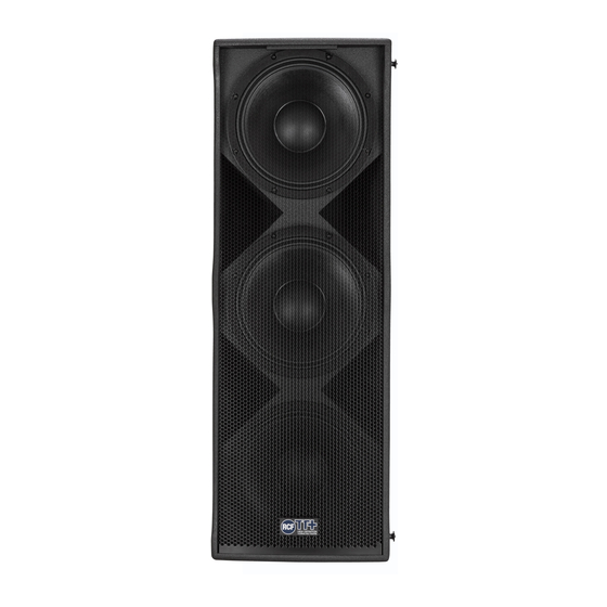
± SPECIFICATIONS µ ÷ TTL6-A TTL6-AS ACOUSTICAL Operating frequency range 45 - 20.000 Hz 35 - 400 Hz Max SPL 139 dB 139 dB Coverage 90° x 30° Crossover frequencies 200, 800 Hz selectable TRANSDUCERS Low frequency 2 x 12” neo, 3.0” v.c.
Need help?
Do you have a question about the TTL6-AS and is the answer not in the manual?
Questions and answers