
Related Manuals for Acer Aspire TC-780


Summary of Contents for Acer Aspire TC-780
- Page 1 Aspire TC-780 Desktop Computer Service Guide Service guide files and updates are available on the Acer/CSD web site; for more information, go to http://gcsd.acer.com.tw/GCSD_Portal/ SG V1.03 PRINTED IN TAIWAN...
- Page 2 Revision History Refer to the table below for changes made on this version of the Aspire TC-780 Desktop Computer Service Guide. Date Version Chapter Updates 05-09-2016 First Draft 05-17-2016 V1.00 09-07-2016 V1.01 Page 1 - Removed Win7x64 driver in “System Features”.
- Page 3 Any Acer Incorporated software described in this guide is sold or licensed "as is". Should the programs prove defective following their purchase, the buyer (and not Acer Incorporated, its distributor, or its dealer) assumes the entire cost of all necessary servicing, repair, and any incidental or consequential damages resulting from any defect in the software.
- Page 4 Alerts you to any physical risk or system damage that might result from doing or not doing specific actions. CAUTION Gives precautionary measures to avoid possible hardware or software problems. IMPORTANT Reminds you to do specific actions relevant to the accomplishment of procedures. Aspire TC-780 Desktop Computer Service Guide...
- Page 5 FRU list of this printed service guide. You MUST use the list provided by your regional Acer office to order FRU parts for repair and service of customer machines. Aspire TC-780 Desktop Computer Service Guide...
- Page 6 Aspire TC-780 Desktop Computer Service Guide...
-
Page 7: Table Of Contents
Removing the Power Button Module ....... . .48 Aspire TC-780 Desktop Computer Service Guide... - Page 8 Aspire TC-780 FRU List........
-
Page 9: Features And Specifications
Chapter 1 Features and Specifications This chapter lists the features and specifications of the Aspire TC-780 Desktop Computer. NOTE The items listed in this section are for reference only. The exact configuration of your PC depends on the model purchased. -
Page 10: Physical Specifications
Packed: -20 to 60 °C (-4 to 140 °F) Unpacked: -10 to 60 °C (14 to 140 °F) Operating humidity -15% to 80% RH non-condensing Non-operating humidity -10% to 90% RH non-condensing at 40 °C Aspire TC-780 Desktop Computer Service Guide... -
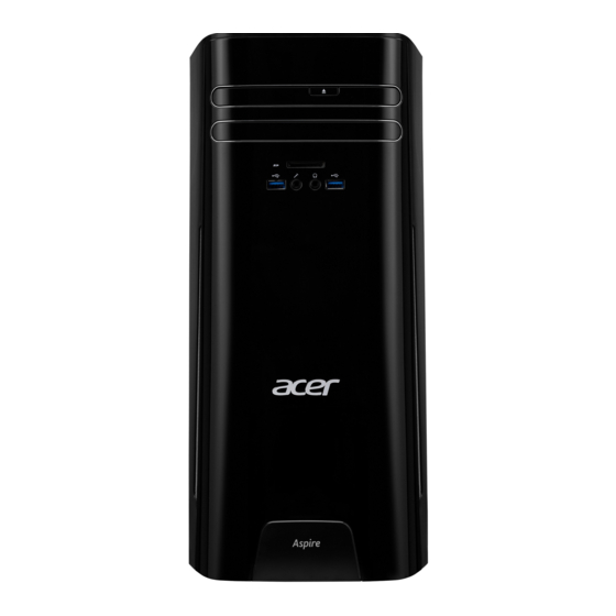
Page 11: System Tour
The pictures and tables in this section illustrate the physical outlook of the computer. Front View Item Component ODD eject button USB 3.0 ports Microphone-in jack SD card reader Headphone jack Dummy ODD bezel ODD emergency eject hole Power button/LED Aspire TC-780 Desktop Computer Service Guide... -
Page 12: Rear View
Rear View Item Component Power connector HDMI ports USB 2.0 ports USB 3.0 port Microphone jack Line-in jack Line-out jack Expansion card slots Expansion card LAN connector Aspire TC-780 Desktop Computer Service Guide... -
Page 13: Hardware Specifications
• HYNIX – 4GB HMA451U6AFR8N / 8GB HMA41GU6AFR8N / 16GB HMA82GU6MFR8N • SAMSUNG – 4GB M378A5143DB0 / 8GB M378A1G43DB0 / 16GB M378A2K43BB1 Population rule Please refer to “Reinstalling the Memory Modules” on page for Memory Population Matrix Table. Aspire TC-780 Desktop Computer Service Guide... -
Page 14: Hard Disk Drive
Integrated in the Intel Skylake H110 chipset Type DVD ROM/SuperMulti Number of ODD bays Form factor Slim type, 9mm Interface SATA 3.0 Write/read speed Vendor and models • HLDS – GUE1N • PLDS – DA-8A6SH Aspire TC-780 Desktop Computer Service Guide... -
Page 15: Card Reader
Item Specification Controller Integrated in the Intel Skylake H110 chipset Connectors • One PCI Express x16 slot (PCIe V3.0) • One PCI Express x1 slot (PCIe V2.0) • Two mini-PCIe M.2 slot (PCIe V3.0) Aspire TC-780 Desktop Computer Service Guide... -
Page 16: Keyboard And Input Devices
• FSP FSP220-50AANA 220W Active PFC 220v-240V • FSP FSP300-60THA(1) 300W None PFC (A01003) 100-127V/220-240V • FSP FSP300-60EP(1) 300W Active PFC (A01007) 100-127v/220v-240V • LITE-ON PS-6301-18A4 300W None PFC 100-127V/220-240V • LITE-ON PS-7501-5AE 500W Active PFC 100-127V/220-240V Aspire TC-780 Desktop Computer Service Guide... -
Page 17: System Utilities
Chapter 2 System Utilities This chapter lists the system utilities installed in Aspire TC-780 Desktop Computer. CMOS Setup Utility CMOS Setup Utility is a hardware configuration program built into the system ROM. Since most systems are already properly configured and optimized, there is normally no need to run this utility. -
Page 18: Accessing The Setup Utility
Some options (marked with a) lead to submenus that enable you to change the values for the option. Use the Up/Down/Left/Right arrow keys to scroll through the items in the submenu Aspire TC-780 Desktop Computer Service Guide... -
Page 19: Navigating Through The Setup Utility
• On one of the primary menu screens, the Exit menu displays. • On a submenu screen, the previous screen displays. • When you are making selections from a pop-up menu, closes the pop- up without making a selection. Aspire TC-780 Desktop Computer Service Guide... -
Page 20: Setup Utility Menus
Official model name of the computer. System Serial Number System serial number. Base Board Serial Number Base board serial number. Asset Tag Number System asset tag number System Date Sets the system date. System Time Sets the system time. Aspire TC-780 Desktop Computer Service Guide... -
Page 21: Advanced
Integrated Peripherals Access this submenu to enable or disable operation modes for the onboard I/O controllers. PC Health Status Access this submenu to view current level of system/processor/PCH temperature, voltages, and fan speed. Aspire TC-780 Desktop Computer Service Guide... - Page 22 Video Output Select which display device the system will use when Discrete the system boots. Onboard Onboard Graphics Select whether to enable or disable the onboard video Enabled Controller controller when the system boots. Disabled Aspire TC-780 Desktop Computer Service Guide...
- Page 23 Enables or disables the load of embedded option ROM Enabled for onboard network controller. Disabled Onboard Wi-Fi module Enables or disables the onboard Wi-Fi module. Enabled Disabled Onboard Bluetooth module Enables or disables the onboard Bluetooth module. Enabled Disabled Aspire TC-780 Desktop Computer Service Guide...
- Page 24 Enables or disables the System Shutdown Temperature Enabled Temperature function. Disabled VRD Shutdown Enables or disables the VRD Shutdown Temperature Enabled Temperature function. Disabled Smart Fan Enables or disables the smart system fan control Enabled function. Disabled Aspire TC-780 Desktop Computer Service Guide...
-
Page 25: Power
USB keyboard or mouse. Disabled Restore On AC Power Enables or disables the system to reboot after a power Power Off Loss failure or interrupt occurs. Power On Last State Aspire TC-780 Desktop Computer Service Guide... -
Page 26: Authentication
Enables or disables the secure boot function. Enabled Disabled Secure Boot Mode Select the secure boot mode when secure boot is Standard enabled. Custom Default Key Provisioning Enables or disables the default key provisioning Enabled function. Disabled Aspire TC-780 Desktop Computer Service Guide... -
Page 27: Security
Enables or disables the Trusted Platform Module (TPM) Enabled function. Disabled TPM Operation Displays the current Trusted Platform Module (TPM) None operation. Enable Take Ownership Disable Take Ownership Clear Hash Policy Displays supported hash policy SHA-1 Aspire TC-780 Desktop Computer Service Guide... - Page 28 Press Enter twice without entering anything in the new and confirm password fields. You will be prompted to confirm the password removal. Press Enter. Press F10 to save the changes you made and close the Setup Utility. Aspire TC-780 Desktop Computer Service Guide...
-
Page 29: Boot Options
• All, but Keyboard – If a keyboard error is detected, No Errors BIOS will pause the system. • All Errors –- Any error detected will pause the system. • No Errors – BIOS will ignore any errors detected during POST Aspire TC-780 Desktop Computer Service Guide... -
Page 30: Exit
Save as User Default Select this option and press Enter to save changes that you have made as Settings user defaults. Load User Default Settings Select this option and press Enter to restore user defaults. Aspire TC-780 Desktop Computer Service Guide... -
Page 31: System Disassembly And Reassembly
Turn off the power to the computer and all peripherals. Unplug the power cord from the computer. Unplug the network cable and all connected peripheral devices from the computer. Place the computer on a flat, steady surface with the rear cover facing upward. Aspire TC-780 Desktop Computer Service Guide... -
Page 32: Disassembly Procedures
Slide the side panel toward the back of the chassis until the tabs on the side panel disengage with the slots on the chassis. Detach the side panel from the unit and put it aside for re-installation later. Aspire TC-780 Desktop Computer Service Guide... -
Page 33: Removing The Front Bezel
Removing the Front Bezel Force eject the ODD tray by inserting a thin metal object into the ODD emergency eject hole. Disengage the latch securing the ODD bezel to the ODD tray, then detach the ODD bezel. Aspire TC-780 Desktop Computer Service Guide... - Page 34 Push back the ODD tray until it latches into place. Release the front bezel retention tabs from the chassis interior. Aspire TC-780 Desktop Computer Service Guide...
- Page 35 Pull the front bezel away from the chassis. Aspire TC-780 Desktop Computer Service Guide...
-
Page 36: Removing The Odd Module
Removing the ODD Module Release all the cables from the twist wire tie securing them to the chassis. Disconnect the power and data combo cable from the ODD module. Aspire TC-780 Desktop Computer Service Guide... - Page 37 Disconnect the power and data combo cable from the power supply cable. Disconnect the ODD data cable from the mainboard. Aspire TC-780 Desktop Computer Service Guide...
- Page 38 Remove the two screws securing the ODD module to the chassis. Quantity Color Torque Part Number Screw Type Silver 6.0 ± 0.5 kgf-cm 86.B1HD1.001 Slide the ODD module out of the chassis. Aspire TC-780 Desktop Computer Service Guide...
- Page 39 Remove the two screws securing the ODD to the ODD bracket. Quantity Color Torque Part Number Screw Type Silver 1.5 ± 0.3 kgf-cm 86.SXLD1.001 Pull the ODD out of the ODD carrier. Aspire TC-780 Desktop Computer Service Guide...
-
Page 40: Removing The Hdd Module
Removing the HDD Module Disconnect the data and power cables from the HDD module. Disconnect the HDD data cable from the mainboard. Aspire TC-780 Desktop Computer Service Guide... - Page 41 Remove the four screws securing the HDD module to the chassis. Quantity Color Torque Part Number Screw Type Silver 6.0 ± 0.5 kgf-cm 86.SXHD1.001 Slide the HDD module out of the chassis. Aspire TC-780 Desktop Computer Service Guide...
-
Page 42: Removing The Thermal Module
Disconnect the heatsink fan cable from the mainboard. Loosen the four captive screws securing the thermal module to the mainboard. Quantity Color Torque Part Number Screw Type Silver 6.0 ± 0.5 kgf-cm Thermal Screws Aspire TC-780 Desktop Computer Service Guide... - Page 43 Remove the thermal module from the mainboard. Aspire TC-780 Desktop Computer Service Guide...
-
Page 44: Removing The Processor
WARNING:The processor becomes very hot when the system is on. Allow it to cool off first before handling. Press the load lever and move it to the right to release the load lever from the retention tab. Pull the load lever to release the CPU cover plate from the retaining post. Aspire TC-780 Desktop Computer Service Guide... - Page 45 Note: WEEE Annex VII component. A circuit board that is >10 cm has been highlighted with a yellow rectangle as shown in the above image. Follow local regulations for disposing this type of circuit board. Aspire TC-780 Desktop Computer Service Guide...
-
Page 46: Removing The Memory Modules
Note: WEEE Annex VII component. A circuit board >10 cm2 has been highlighted with the yellow rectangle as shown above. Please follow local regulations for disposal of detached circuit boards. Repeat Step 1 to remove the remaining memory module. Aspire TC-780 Desktop Computer Service Guide... -
Page 47: Removing The Expansion Board
Remove the screw securing the expansion board bracket to the chassis. Quantity Color Torque Part Number Screw Type Silver 6.0 ± 0.5 kgf-cm 86.SPZD1.003 Unlatch the metal clip securing the expansion board bracket to the chassis. Aspire TC-780 Desktop Computer Service Guide... - Page 48 Remove the PCIe x16 expansion board from its slot. Note: WEEE Annex VII component. A circuit board >10 cm2 has been highlighted with the yellow rectangle as shown above. Please follow local regulations for disposal of detached circuit boards. Aspire TC-780 Desktop Computer Service Guide...
-
Page 49: Removing The Wlan Module
NOTE: For reference during machine reassembly, note which cable color corresponds to the main and auxiliary connectors. Remove the screw securing the WLAN module to the mainboard. Quantity Color Torque Part Number Screw Type Silver 1.5 ± 0.3 kgf-cm 86.NBY01.003 Aspire TC-780 Desktop Computer Service Guide... - Page 50 Remove the WLAN module from the mainboard. Note: WEEE Annex VII component. A circuit board >10 cm2 has been highlighted with the yellow rectangle as shown above. Please follow local regulations for disposal of detached circuit boards. Aspire TC-780 Desktop Computer Service Guide...
-
Page 51: Removing The Ssd Module
Remove the SSD module from the mainboard. Note: WEEE Annex VII component. A circuit board >10 cm2 has been highlighted with the yellow rectangle as shown above. Please follow local regulations for disposal of detached circuit boards. Aspire TC-780 Desktop Computer Service Guide... -
Page 52: Removing The Power Supply Module
Disconnect the power supply cables from the mainboard. Remove the four screws securing the rear end of the power supply module to the chassis. Quantity Color Torque Part Number Screw Type Silver 6.0 ± 0.5 kgf-cm 86.SPZD1.003 Aspire TC-780 Desktop Computer Service Guide... - Page 53 Pull the power supply module out of the chassis. Aspire TC-780 Desktop Computer Service Guide...
-
Page 54: Removing The Front I/O And Card Reader Assembly
Disconnect the front I/O board and card reader board cables from the mainboard. Remove the screw securing the front I/O and card reader bracket to the chassis. Quantity Color Torque Part Number Screw Type Silver 6.0 ± 0.5 kgf-cm 86.SPZD1.003 Aspire TC-780 Desktop Computer Service Guide... - Page 55 Pull the bracket with the cables out of the chassis. Aspire TC-780 Desktop Computer Service Guide...
-
Page 56: Removing The Power Button Module
Removing the Power Button Module Disconnect the power button and LED cable from the mainboard. Release the power button cable from the plastic clip securing it to the chassis. Aspire TC-780 Desktop Computer Service Guide... - Page 57 Slide the top cover to disengage the latches securing it to the chassis, then remove the top cover. Pull the power button cable out of the chassis. Aspire TC-780 Desktop Computer Service Guide...
-
Page 58: Removing The Mainboard
Gently lift the mainboard off the chassis. Note: WEEE Annex VII component. A circuit board >10 cm2 has been highlighted with the yellow rectangle as shown above. Please follow local regulations for disposal of detached circuit boards. Aspire TC-780 Desktop Computer Service Guide... - Page 59 Please follow local regulations for disposal of used batteries. Caution: Risk of explosion if battery is replaced by an incorrect type. Dispose of used batteries according to the instructions. Aspire TC-780 Desktop Computer Service Guide...
-
Page 60: Reassembly Procedures
Slide the RTC battery into its socket in the mainboard (1) then push it down (2) until it latches into place. Slide the mainboard into the chassis, with the I/O ports of the mainboard extruding from their port holes, then lower the mainboard in place. Aspire TC-780 Desktop Computer Service Guide... - Page 61 Secure the mainboard to the chassis using six screws. Quantity Color Torque Part Number Screw Type Silver 6.0 ± 0.5 kgf-cm 86.SPZD1.003 Aspire TC-780 Desktop Computer Service Guide...
-
Page 62: Reinstalling The Power Button Module
Reinstalling the Power Button Module Insert the power button cable into the chassis. Place the top cover into its socket in the chassis and push until it latches into place. Aspire TC-780 Desktop Computer Service Guide... - Page 63 Use the plastic clip to secure the power button cable to the chassis. Connect the power button and LED cable to the mainboard. Aspire TC-780 Desktop Computer Service Guide...
-
Page 64: Reinstalling The Front I/O And Card Reader Assembly
Insert the cables and place the front I/O and card reader assembly in its socket. Secure the front I/O and card reader bracket to the chassis using one screw. Quantity Color Torque Part Number Screw Type Silver 6.0 ± 0.5 kgf-cm 86.SPZD1.003 Aspire TC-780 Desktop Computer Service Guide... - Page 65 Connect the front I/O and card reader board cables to the mainboard. Aspire TC-780 Desktop Computer Service Guide...
-
Page 66: Reinstalling The Power Supply Module
Slide the power supply module into its socket in the chassis. Secure the rear end of the power supply module to the chassis using four screws. Quantity Color Torque Part Number Screw Type Silver 6.0 ± 0.5 kgf-cm 86.SPZD1.003 Aspire TC-780 Desktop Computer Service Guide... - Page 67 Connect the power supply cables to the mainboard. Aspire TC-780 Desktop Computer Service Guide...
-
Page 68: Reinstalling The Ssd Module
Reinstalling the SSD Module Insert the SSD module into the mainboard. Secure the SSD module to the mainboard using one screw. Quantity Color Torque Part Number Screw Type Silver 1.5 ± 0.3 kgf-cm 86.NBY01.003 Aspire TC-780 Desktop Computer Service Guide... -
Page 69: Reinstalling The Wlan Module
Reinstalling the WLAN Module Insert the WLAN module into the mainboard. Secure the WLAN module to the mainboard using one screw. Quantity Color Torque Part Number Screw Type Silver 1.5 ± 0.3 kgf-cm 86.NBY01.003 Aspire TC-780 Desktop Computer Service Guide... - Page 70 Connect the WLAN antenna cables to the WLAN module. NOTE: Refer to your machine disassembly note to determine which cable color corresponds to the main and auxiliary connectors. Aspire TC-780 Desktop Computer Service Guide...
-
Page 71: Reinstalling The Expansion Board
Insert the PCIe x16 expansion board into its slot, then press it down until it latches into place. Press the metal clip securing the expansion board bracket to the chassis until it latches into place. Aspire TC-780 Desktop Computer Service Guide... - Page 72 Secure the expansion board bracket to the chassis using one screw. Quantity Color Torque Part Number Screw Type Silver 6.0 ± 0.5 kgf-cm 86.SPZD1.003 Aspire TC-780 Desktop Computer Service Guide...
-
Page 73: Reinstalling The Memory Modules
Insert the memory module into the DIMM slot (1) then press it down until it latches into place (2). Repeat Step 1 to install the remaining memory module. IMPORTANT When installing DIMM modules, populate the DIMM slots according to the table below: Size DIMM1 DIMM2 Aspire TC-780 Desktop Computer Service Guide... -
Page 74: Reinstalling The Processor
NOTE: Make sure the gold arrow on the corner of the processor is aligned with the beveled corner of the socket. The processor will easily fit into the socket if it is properly oriented. Replace the CPU cover plate. Aspire TC-780 Desktop Computer Service Guide... - Page 75 Pull down the load lever, making sure the cover plate latch into the retaining post. Slide the load lever to the left until it latches into the retention tab. Aspire TC-780 Desktop Computer Service Guide...
-
Page 76: Reinstalling The Thermal Module
Place the thermal module into the mainboard. Tighten the four captive screws to secure the thermal module to the mainboard. Quantity Color Torque Part Number Screw Type Silver 6.0 ± 0.5 kgf-cm Thermal Screws Aspire TC-780 Desktop Computer Service Guide... - Page 77 Connect the thermal module fan cable to the mainboard. Aspire TC-780 Desktop Computer Service Guide...
-
Page 78: Reinstalling The Hdd Module
Reinstalling the HDD Module Slide the HDD module into the chassis. Secure the HDD module to the chassis using four screws. Quantity Color Torque Part Number Screw Type Silver 6.0 ± 0.5 kgf-cm 86.SXHD1.001 Aspire TC-780 Desktop Computer Service Guide... - Page 79 Connect the HDD data cable to the mainboard. Connect the data and power cables to the HDD module. Aspire TC-780 Desktop Computer Service Guide...
-
Page 80: Reinstalling The Odd Module
Reinstalling the ODD Module Place the ODD into the ODD bracket. Secure the ODD to the ODD bracket using two screws. Quantity Color Torque Part Number Screw Type Silver 1.5 ± 0.3 kgf-cm 86.SXLD1.001 Aspire TC-780 Desktop Computer Service Guide... - Page 81 Slide the ODD module into the chassis. Secure the ODD module to the chassis using two screws. Quantity Color Torque Part Number Screw Type Silver 6.0 ± 0.5 kgf-cm 86.B1HD1.001 Aspire TC-780 Desktop Computer Service Guide...
- Page 82 Connect the ODD data cable to the mainboard. Connect the power and data combo cable to the power supply cable. Aspire TC-780 Desktop Computer Service Guide...
- Page 83 Connect the power and data combo cable to the ODD module. Use the twist wire tie to secure all the cables to the chassis. Aspire TC-780 Desktop Computer Service Guide...
-
Page 84: Reinstalling The Front Bezel
Insert the tabs on the front bezel into the notches on the right side of the chassis, then rotate the front bezel in the direction indicated. Push the front bezel until the retention tabs latch into place and are securely fastened to the chassis interior. Aspire TC-780 Desktop Computer Service Guide... - Page 85 Force eject the ODD tray by inserting a thin metal object into the ODD emergency eject hole. Place the bezel into the ODD tray (1), then press until the latches lock into place (2). Aspire TC-780 Desktop Computer Service Guide...
- Page 86 Push back the ODD module into its slot until it latches into place. Aspire TC-780 Desktop Computer Service Guide...
-
Page 87: Reinstalling The Side Panel
Slide the side panel toward the front of the chassis until the tabs on the side panel engage with the slots on the chassis. Secure the side panel to the chassis using two screws. Quantity Color Torque Part Number Screw Type Black 6.0 ± 0.5 kgf-cm 86.SR2D1.001 Aspire TC-780 Desktop Computer Service Guide... - Page 88 Aspire TC-780 Desktop Computer Service Guide...
-
Page 89: Troubleshooting
This chapter provides instructions on how to troubleshoot system hardware problems. Hardware Diagnostic Procedure IMPORTANT The diagnostic tests described in this chapter are only intended to test Acer products. Non- Acer products, prototype cards, or modified options can give false errors and invalid system responses. -
Page 90: Checkpoints
Verify that all power and data cables are firmly and properly attached to the installed drives. Verify that all cable connections inside the system are firmly and properly attached to their appropriate mainboard connectors. Verify that all components are Acer-qualified and supported. 10. Reinstall the side panel. 11. Power on the system. - Page 91 Erase the flash part. Program the flash part. The flash has been updated successfully. Make flash write disabled. Disable ATAPI hardware. Restore CPUID value back into register. Give control to F000 ROM at F000:FFF0h. Aspire TC-780 Desktop Computer Service Guide...
- Page 92 Display total memory in the system. Mid POST initialization of chipset registers. Detect different devices (Parallel ports, serial ports, and coprocessor in CPU, ... etc.) successfully installed in the system and update the BDA, EBDA…etc. Aspire TC-780 Desktop Computer Service Guide...
- Page 93 Uninstall POST INT1Ch vector and INT09h vector. Deinitializes the ADM module. Prepare BBS for Int 19 boot. End of POST initialization of chipset registers. Save system context for ACPI. Passes control to OS Loader (typically INT19h). Aspire TC-780 Desktop Computer Service Guide...
-
Page 94: Post Error Indicators
IMPORTANT: If your system fails after you make changes in the Setup menus, reboot the computer, enter Setup again and load Setup defaults to correct the error. Aspire TC-780 Desktop Computer Service Guide... - Page 95 The IDE/ATAPI device configured as Secondary Master could not be properly Hard Disk Error initialized by the BIOS. This message is typically displayed when the BIOS is trying to detect and configure IDE/ATAPI devices in POST. Aspire TC-780 Desktop Computer Service Guide...
- Page 96 The IDE/ATAPI device configured as Slave in the 4th IDE controller failed an ATAPI ATAPI Incompatible compatibility test. This message is typically displayed when the BIOS is trying to detect and configure IDE/ATAPI devices in POST. Aspire TC-780 Desktop Computer Service Guide...
- Page 97 Detection is enabled in AMIBIOS setup. VIRUS: Continue If the BIOS detects possible virus activity, it will prompt the user. This message will (Y/N)? only be displayed if Virus Detection is enabled in AMIBIOS setup. Aspire TC-780 Desktop Computer Service Guide...
- Page 98 CMOS battery is low. This message usually indicates that the CMOS battery needs to be replaced. It could also appear when the user intentionally discharges the CMOS battery. CMOS Settings CMOS settings are invalid. This error can be resolved by using AMIBIOS Setup. Wrong Aspire TC-780 Desktop Computer Service Guide...
- Page 99 Error code = 004Ah ROM. Unknown BIOS error. This message is displayed when language module is not present in the AMIBIOS8 Error code = 004Bh ROM. Floppy Controller Error in initializing legacy Floppy Controller. Failure Aspire TC-780 Desktop Computer Service Guide...
- Page 100 Blinking cursor only; system does not work. • IDE drive connection/cables • IDE disk drives • See “Undetermined Problems”. • Mainboard NOTE: Ensure the memory modules are installed properly and the contact leads are clean before diagnosing any system problems. Aspire TC-780 Desktop Computer Service Guide...
- Page 101 • CD/DVD-ROM drive. NOTE: Make sure the optical disc drive is configured correctly in CMOS Setup, the cable/jumper are set correctly and the drive’s optical lens is clean before diagnosing any optical drive problems. Aspire TC-780 Desktop Computer Service Guide...
- Page 102 • Missing, broken, or incorrect characters • Mainboard • Blank monitor (dark) • Blank monitor (bright) • Distorted image • Unreadable monitor Display changing colors. • Monitor signal connection/cable • Video adapter card • Mainboard Aspire TC-780 Desktop Computer Service Guide...
- Page 103 Windows Start menu does not turn off the • Reload software from Recovery CD. system. (Only pressing power button can turn off the system). No system power, or power supply fan is • Power supply not running. • Mainboard Aspire TC-780 Desktop Computer Service Guide...
- Page 104 If the problem does not recur, reconnect the removed devices one at a time until you find the failed FRU. If the problem persists, replace the mainboard, and then LCD assembly (one at a time). Do not replace a non- defective FRU. Aspire TC-780 Desktop Computer Service Guide...
-
Page 105: Bios Recovery
Press the power button to turn on the system. The system will now execute the BIOS recovery process. You will hear a long beep followed by a short beep. Select Proceed with flash update to start recovery. Aspire TC-780 Desktop Computer Service Guide... - Page 106 Wait for the program to finish with the recovery. Flash update completed. Press any key to reboot system. 10. The BIOS recovery is now completed. Aspire TC-780 Desktop Computer Service Guide...
-
Page 107: Bios Update
Press Delete when the company logo is displayed on the screen to enter BIOS Setup Menu. Go to the Authentication page, select Secure Boot and press Enter. Select Disabled to disable Secure Boot. Go to the Exit page, select Save and Exit Setup and press Enter. Aspire TC-780 Desktop Computer Service Guide... - Page 108 14. Press the power button to turn on the system. The system will now execute the BIOS update process. 15. Press Delete when the company logo is displayed on the screen to enter BIOS Setup Menu. Aspire TC-780 Desktop Computer Service Guide...
- Page 109 16. Go to the Exit page, select Load Default Setting and press Enter. Select Yes to load default setting. 17. Select Save and Exit Setup and press Enter. 18. Select Yes to Restart. Aspire TC-780 Desktop Computer Service Guide...
-
Page 110: Clearing Cmos
14. During POST, press Delete to access the Setup Utility. 15. Press F9 to load the system default values. 16. Press F10 to save the changes you made and close the Setup Utility. Aspire TC-780 Desktop Computer Service Guide... -
Page 111: System Architecture
Chapter 5 System Architecture This chapter shows the block diagram and board layout of the Aspire TC-780 Desktop Computer. Block Diagram The core subsystems of the Aspire TC-780 computer are depicted in the following block diagram: Aspire TC-780 Desktop Computer Service Guide... -
Page 112: Mainboard Layout
SATA 6Gb/s connector U3RJ1 RJ45 + USB 3.0 ports USB3F1 Front panel USB 3.0 USB2R1 Rear USB2.0 ports connector 1 SATA0 SATA 6Gb/s connector HDMI2 HDMI port CMOS1 Clear CMOS jumper HDMI1 HDMI port Aspire TC-780 Desktop Computer Service Guide... -
Page 113: Field Replaceable Unit (Fru) List
Chapter 6 Field Replaceable Unit (FRU) List This chapter gives you the FRU (Field Replaceable Unit) listing of the Aspire TC-780 Desktop Computer global configurations. Refer to this list when ordering for repair parts or for RMA (Return Merchandise Authorization). -
Page 114: Exploded Diagram
Power Supply Unit DC.2201B.006 Rear I/O Cover 360.05Z08.0001 Main Chassis DC.13111.05E KO.0080D.019 ODD Top Bezel 360.05Y07.0001 ODD Bottom Bezel 360.05Y06.0001 Front I/O Board DA.13711.007 Card Reader DC.10411.01A Front I/O Bracket 360.02E07.0001 Front Bezel 360.05Y05.0001 Aspire TC-780 Desktop Computer Service Guide... -
Page 115: Aspire Tc-780 Fru List
WIRELESS LAN BOARD INTEL WLAN KI.STN01.101 INT3165.NGWG C0 STONE PEAK 1X1 AC + BT CABLES POWER CORD 110V 3PIN UL USA 27.01518.0I1 POWER CORD 1800MM 250V EURO 27.01518.0J1 POWER CORD 250V CCC 1800MM PRC 27.01518.0K1 Aspire TC-780 Desktop Computer Service Guide... - Page 116 CRT COVER 42.SF601.001 HDMI DUMMY COVER 42.SF601.002 WIFI COVER 42.SXLD1.001 FRONT IO BRACKET 60.B1HD1.003 ODD BRACKET 60.B1HD1.011 DUMMY ODD BRACKET 60.B1HD1.013 IO SHIELDING 60.B57D1.001 IO SHIELDING -FOR VGA HDMI*2 WITH QUARD 60.B57D1.008 PORT USB2.0 Aspire TC-780 Desktop Computer Service Guide...
- Page 117 KC.77A01.CI7 1151 65W Kaby Lake DVD-RW DRIVE ODD PANASONIC BD RW 9.0MM TRAY 6X KO.00607.010 UJ272QBAA2-B LF+HF W/O BEZEL SATA SUPER-MULTI DRIVE HLDS SUPER-MULTI DRIVE KO.0080D.019 9.0MM TRAY 8X GUE1N LF+HF W/O BEZEL SATA Aspire TC-780 Desktop Computer Service Guide...
- Page 118 21K2TA0 (XL1000C) SATA III 32MB LF F/ W:01.01A01 SOLID STATE DRIVE FLASH DISK KINGSTON SSD NAND 96GB RBU- KN.09607.001 SNS8151S3/96GG LF+HF FLASH DISK TOSHIBA SSD NAND 128GB KN.1280A.008 THNSNJ128G8NY LF+HF FLASH DISK LITE-ON SSD NAND 128GB CV1- KN.1280L.013 8B128 LF+HF Aspire TC-780 Desktop Computer Service Guide...
- Page 119 SWEDISH W/DK.RF41B.04H & DC.11211.00W KEYBOARD KIT LITE-ON SK-9662 RF2.4 BLACK 6K.SUYD1.014 UK W/DK.RF41B.04J & DC.11211.00W KEYBOARD KIT LITE-ON SK-9662 RF2.4 BLACK 6K.SUYD1.015 DUTCH W/DK.RF41B.04K & DC.11211.00W KEYBOARD KIT LITE-ON SK-9662 RF2.4 BLACK 6K.SUYD1.016 SWISS/G W/DK.RF41B.04L & DC.11211.00W Aspire TC-780 Desktop Computer Service Guide...
- Page 120 & DC.11211.00W KEYBOARD KIT LITE-ON SK-9662 RF2.4 BLACK 6K.SUYD1.035 CZECH/SLOVAK W/DK.RF41B.057 & DC.11211.00W KEYBOARD KIT LITE-ON SK-9662 RF2.4 BLACK 6K.SUYD1.036 SWISS/FR W/DK.RF41B.058 & DC.11211.00W KEYBOARD KIT LITE-ON SK-9662 RF2.4 BLACK 6K.SUYD1.037 KOREAN W/DK.RF41B.059 & DC.11211.00W Aspire TC-780 Desktop Computer Service Guide...
- Page 121 DK.USB1B.07B NORWEGIAN KEYBOARD LITE-ON SK-9626 USB BLACK DK.USB1B.07C HEBREW NEW LAYOUT FOR EMEA KEYBOARD LITE-ON SK-9626 USB BLACK DK.USB1B.07D POLISH KEYBOARD LITE-ON SK-9626 USB BLACK DK.USB1B.07E SLOVENIAN KEYBOARD LITE-ON SK-9626 USB BLACK DK.USB1B.07F SLOVAK Aspire TC-780 Desktop Computer Service Guide...
- Page 122 KEYBOARD PRIMAX KBAY211 USB BLACK US DK.USB1P.0CC KEYBOARD PRIMAX KBAY211 USB BLACK DK.USB1P.0CD THAILAND KEYBOARD PRIMAX KBAY211 USB BLACK DK.USB1P.0CE SPANISH KEYBOARD PRIMAX KBAY211 USB BLACK DK.USB1P.0CF PORTUGUESE KEYBOARD PRIMAX KBAY211 USB BLACK DK.USB1P.0CG BRAZILIAN PORTUGUESE Aspire TC-780 Desktop Computer Service Guide...
- Page 123 KEYBOARD PRIMAX KBAY211 USB BLACK DK.USB1P.0D4 NORDIC KEYBOARD PRIMAX KBAY211 USB BLACK DK.USB1P.0D5 ENGLISH/CANADIAN FRENCH KEYBOARD PRIMAX KBAY211 USB BLACK DK.USB1P.0DC ARABIC/ENGLISH NEW LAYOUT FOR EMEA KEYBOARD PRIMAX KBAY211 USB BLACK DK.USB1P.0DD TURKMEN NEW LAYOUT FOR EMEA Aspire TC-780 Desktop Computer Service Guide...
- Page 124 KEYBOARD PRIMAX KBAY211 USB BLACK DK.USB1P.0DH HEBREW NEW LAYOUT FOR EMEA MAINBOARD MAIN BOARD KIT ASPIRE TC-760 INTEL H110 N N DB.B4M11.002 RTL8111GA N ACER LOGO DTX W/O 1394 V1.0 LF+HF MEMORY MEMORY SAMSUNG UNB-DIMM DDRIV 2133 KN.16G0B.016 16GB M378A2K43BB1-CPB LF+HF 1024*8 25NM...
- Page 125 SCREW MA HEX 6-32 L5 BLACK 3NOD 86.SR2D1.001 SCREW M2 L2.5 NI JF 86.SXLD1.001 SCREW MACH PAN M3*L4 NI NYLOK 86.VBK01.003 SPEAKER JS SPEAKER USB MS1238UA WITH NEW ACER SP.10600.049 LOGO (MEET AJC SPEC.) Aspire TC-780 Desktop Computer Service Guide...
- Page 126 Aspire TC-780 Desktop Computer Service Guide...
-
Page 127: Test Compatible Components
Appendix A Test Compatible Components This computer’s compatibility is tested and verified by Acer’s internal testing department. All of its system functions are tested for both the Home Basic and Home Premium editions of Microsoft’s Windows 10 operating system. Refer to the following lists for components, adapter cards, and peripherals which have passed these tests. - Page 128 U3x2, vendor p/n: L43F1024-DT-R Daughter board (30L) Mingji U3=450mm, Audio=600mm, HD audio x2, DA.13711.007 U3x2, vendor p/n: 9143-0100009RII External JS speaker USB MS1238UA with new acer SP.10600.049 Speaker logo SEAGATE HDD SEAGATE 3.5" 5900rpm 4000GB KH.04K01.003 ST4000DM000 (Lombard) SATA III 64MB LF F/W:CC54 SEAGATE HDD SEAGATE 3.5"...
- Page 129 Keyboard LITE-ON SK-9626 USB Black DK.USB1B.07G Russian new layout for EMEA Keyboard Lite-On Keyboard LITE-ON SK-9626 USB Black DK.USB1B.07F Slovak Keyboard Lite-On Keyboard LITE-ON SK-9626 USB Black DK.USB1B.07E Slovenian Keyboard Lite-On Keyboard LITE-ON SK-9626 USB Black DK.USB1B.06Y Spanish Aspire TC-780 Desktop Computer Service Guide...
- Page 130 DK.RF41B.056 English/Canadian French Keyboard Lite-On Keyboard LITE-ON SK-9662 RF2.4 Black DK.RF41B.04G French Keyboard Lite-On Keyboard LITE-ON SK-9662 RF2.4 Black DK.RF41B.04E German Keyboard Lite-On Keyboard LITE-ON SK-9662 RF2.4 Black DK.RF41B.04W Greek new layout for EMEA Aspire TC-780 Desktop Computer Service Guide...
- Page 131 Keyboard LITE-ON SK-9662 RF2.4 Black DK.RF41B.049 Thailand Keyboard Lite-On Keyboard LITE-ON SK-9662 RF2.4 Black DK.RF41B.046 Traditional Chinese Keyboard Lite-On Keyboard LITE-ON SK-9662 RF2.4 Black DK.RF41B.050 Turkish Keyboard Lite-On Keyboard LITE-ON SK-9662 RF2.4 Black DK.RF41B.051 Turkish-Q Aspire TC-780 Desktop Computer Service Guide...
- Page 132 DK.RF41B.05B with Rupee Symbol for India MB Kit Wistron MB Kit Aspire T3-780; Aspire X3-780 Intel DB.B5711.001 H110 N N RTL8111GA Acer Logo DTX W/O 1394 V1.0 LF+HF MB Kit Wistron MB Kit Aspire TC-760 Intel H110 N N DB.B4M11.002 RTL8111GA N Acer Logo DTX W/O 1394 V1.0 LF+HF...
- Page 133 VGA card VGA Card nVidia GT730 DDRIII 2GB ATX DA.73011.001 (30L) PCI-Ex16 UEFI DVI HDMI 288-6N326-X01A8 VGA card VGA Card nVidia GTX745 DDRIII 4GB ATX DA.74511.003 (30L) PCI-Ex16 UEFI DVI HDMI MEM 288-1N249- X04A8 Aspire TC-780 Desktop Computer Service Guide...
- Page 134 Intel WLAN Intel WLAN 7265.NGWG.W D0 KI.STN01.008 Stonepeak M.2 2X2 AC + BT 2230 WLAN/BT Lite-On Wireless LAN Liteon 802.11ac Bluetooth FM KE.11A0L.001 3rd WiFi 1x1 AC+ BT M.2 QCA9377A QCA NFA435A, Rev 1.1 Aspire TC-780 Desktop Computer Service Guide...
-
Page 135: Online Support Information
This appendix describes online technical support services available to help you repair your Acer products. If you are a distributor, dealer, ASP or TPM, please refer your technical queries to your local Acer branch office. Acer branch offices and regional business units can access our website. However some information sources will require a user ID and password. - Page 136 Aspire TC-780 Desktop Computer Service Guide...
-
Page 137: Index
LAN port WLAN 7 specifications 7 connector LAN 4 main board placement 104 PS/2 keyboard 4 main unit disassembly audio board 46, 56 DIM checkpoints 86 heat sink 34, 41, 43, 68 disassembly procedures Aspire TC-780 Desktop Computer Service Guide... - Page 138 1 specifications audio 7, 8 Ethernet controller 7 hard disk drive 6 memory 5 optical disc drive 6 power supply unit 8 system chipsets 5 WLAN controller 7 supervisor password 19 Aspire TC-780 Desktop Computer Service Guide...
Need help?
Do you have a question about the Aspire TC-780 and is the answer not in the manual?
Questions and answers
motherboard battery positive up or down?
The motherboard battery (RTC battery) in an Acer Aspire TC-780 should be installed by sliding it into its socket and pushing it down. Typically, RTC batteries are CR2032 coin-cell batteries, which are installed with the positive (+) side facing up.
This answer is automatically generated
motherboard battery positive up or down?