Table of Contents
Advertisement
Quick Links
Instrument Manual
PR 5211 Transmitter Series
PR 5211/00 ProfiBus Transmitter
PR 5211/10 Digital Process Transmitter
PR 5211/11 ProfiBus Transmitter (without Analog Output)
Instrument Manual
for PR 5211
Sartorius Mechatronics T&H GmbH, Meiendorfer Str. 205, 22145 Hamburg, Germany
Tel:+49.40.67960.303
9499 050 52100
Release 6.00
Fax:+49.40.67960.383
Edition 1
20.01.2014
Advertisement
Table of Contents

Related Manuals for Sartorius PR 5211 Series


Summary of Contents for Sartorius PR 5211 Series
- Page 1 PR 5211/00 ProfiBus Transmitter PR 5211/10 Digital Process Transmitter PR 5211/11 ProfiBus Transmitter (without Analog Output) Instrument Manual 9499 050 52100 Edition 1 20.01.2014 for PR 5211 Release 6.00 Sartorius Mechatronics T&H GmbH, Meiendorfer Str. 205, 22145 Hamburg, Germany Tel:+49.40.67960.303 Fax:+49.40.67960.383...
- Page 2 Any information in this document is subject to change without notice and does not represent a commitment on the part of SARTORIUS. This product should be operated only by trained and qualified personnel. In correspondence concerning this product the type, name and release number as well as all license numbers in relation to the product have to be quoted.
-
Page 3: Table Of Contents
RS-485 Interface ..................................14 3.2.3 Analog Output ..................................16 3.2.4 3 Opto Inputs .................................... 17 3.2.5 3 Opto Outputs ..................................18 3.2.6 Load Cell Connection ................................19 3.2.7 ProfiBus Interface (for PR 5211/00 and PR 5211/11 only) ..................23 Sartorius EN-1... - Page 4 Invoke Scale Diagnostics ............................... 49 5.3.10 About Scale First Line ................................49 5.3.11 About Scale Scroll ................................... 50 5.3.12 Scale Information ..................................50 5.3.13 Scale Information Scroll ................................ 50 5.3.14 Abort Command ..................................50 5.3.15 Repeat Displayed Weight Continuously ........................... 50 EN-2 Sartorius...
- Page 5 Register 80…93: Action bits state controlled (write) ....................68 6.2.15 Register 112…125: Action bits transition controlled (write) ..................69 ProfiBus Parameter Numbers ..............................70 6.3.1 Configuration parameter ..............................70 6.3.2 Calibration ....................................73 6.3.3 ADU parameter ..................................75 6.3.4 Parameter P99: Access Code ..............................80 Sartorius EN-3...
- Page 6 Index ..................................89 Appendix ..................................91 12.1 Pin Assignment for Interface RS-485 ............................91 12.2 EC Declaration of Conformity ..............................91 12.3 GSD File for ProfiBus DP ................................91 12.4 Spare Parts ......................................91 12.5 Example Print Out ..................................92 EN-4 Sartorius...
-
Page 7: Safety Hints
Check the contents of the consignment for completeness and note whether any damage has occurred during transport. If the content is incomplete or damaged, a claim must be filed with the carrier immediately and the Sartorius sales or service organization must be informed to permit repair or replacement of the unit. -
Page 8: Installation
Supply Voltage Connection The supply voltage is 24 V DC +10 %/-15 %. The power consumption is 8.2 W maximum. For connection to 230/115 V AC an external power supply (e.g. Sartorius PR 1624/00 or Phoenix Mini Power) is required. EN-6... -
Page 9: Failure And Excessive Stress
Connect mounting rail to protective earth. Install measure and data cables separately from power cables. Pos. Designation Mounting rail (35 mm) Screen clamp (e.g. Phoenix SK8-D) Screen rail (e.g. Phoenix NLS-CU 3/10) Rail connection (e.g. Phoenix AB-SK 65D) Sartorius EN-7... -
Page 10: Pr 5211 Transmitter Series
This version has digital in and outputs and USB-B connection for the configuration of the device. Via serial output an e.g. remote display can be connected. This version is equipped with a ProfiBus connection, but not with an analog output. The respective menus in the operating tools are adapted to it. EN-8 Sartorius... -
Page 11: Transmitter Survey
Analog Output value defined by ProfiBus (PR 5211/00 only) Digital Input 3 channels, galvanically isolated Digital Output 3 channels, galvanically isolated Communication protocols For the internal RS-485: Remote display protocol SMA protocol Slave: PR 5211/00 ProfiBus-DP PR 5211/11 ProfiBus-DP Sartorius EN-9... -
Page 12: Label On The Housing
The wiring principle is located at the side of the housing: Housing Dimensions Open Housing To open the housing, press the four closings (two on each side). During assembly, take care of the earth connection in the bottom of the housing. EN-10 Sartorius... -
Page 13: Display
* The LED for ProfiBus activity (PR 5211/00 and PR 5211/11 only) is activated if a connection has been established. It remains on, even if the communication is not running or the physical connection is interrupted! 2.6.1.2 Weight status indication Standstill Center zero Below zero or above FSD Sartorius EN-11... -
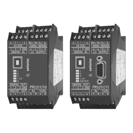
Page 14: Overview Of Connections
PR 5211 Transmitter Series PR 5211 Instrument Manual Overview of Connections EN-12 Sartorius... -
Page 15: Installing The Instrument
The configuration and calibration can be carried out from the PC program ConfigureIt! Via (release 6.00 or higher) the USB interface, see Chapter 4.4 and 4.5. Connection USB-B connector USB 2.0 A>B Connection cable Cable length Max. 5 m Sartorius EN-13... -
Page 16: Rs-485 Interface
The RS-485-receiver (Rx) has an internal terminal resistance of 120 ¥ and 1.6 k¥ to the internal bus supply voltage (- at RxA + at RxB). 3.2.2.1 Connecting to PC or to RS-485 Converter Point-to-point connection for the SMA protocol. Configuration PR 5211/.. [Parameter]-[Communication]: ’SMA protocol’ EN-14 Sartorius... - Page 17 – – – – The following operations are possible from the connected remote display: Indicate current value type Set tare Reset tare Set zero Sartorius EN-15...
-
Page 18: Analog Output
Cable length (screened) 150 m (current output) 0/4…20mA analog signal, current output The current is supplied directly from the terminals. 0…10V analog signal, voltage output The voltage level corresponds to the voltage drop at the 500 Ohm (10 ppm/K) resistor. EN-16 Sartorius... -
Page 19: Opto Inputs
< 5 mA @ 12 VDC Potential isolation Yes, 3 inputs have got 1 common minus potential Example: contact input connection When a voltage ≥10 V DC is applied to the terminals (in the example: 1-GND), input 1 is active (true). Sartorius EN-17... -
Page 20: Opto Outputs
For protection of the output circuit, relays with free-wheel diode must be provided. Example: voltage output connection When output 1 is active (true), the output voltage changes from 24/12 V DC into <3 V DC. A load resistance of 2.2/1 k¥ must be provided. EN-18 Sartorius... -
Page 21: Load Cell Connection
Installing the Instrument 3.2.6 Load Cell Connection The cable colours shown in this chapter are of Sartorius load cells series PR 62XX. Before connection of other types, strictly necessary read the instructions concerning cable colours of the load cell/platform. •... - Page 22 (symmetrical to housing GND) Measuring voltage M+ to M- : 0 - 12 mV @ WZ mit 1,0 mV/V 0 - 24 mV @ WZ mit 2,0 mV/V Measuring voltage Ground (earth) to M- : 0 V ±0,5 V EN-20 Sartorius...
- Page 23 The common line of the symmetrical external supply has to be connected to the same terminal at PR 5211 as the screen of the load cell cable/connecting cable. Specification external supply: 6 V DC +5 %, -30 %; ripple max. 50 mVpp; asymmetry max. ±3 %. Sartorius EN-21...
- Page 24 PR 5211/xx: Solder link J300 must be opened on the A/D converter print (0 ¥ resistance removed). Delivery condition: Solder link is closed with 0 ¥ resistance. Note: When J300 is open; Sense voltage monitoring is switched off! EN-22 Sartorius...
-
Page 25: Profibus Interface (For Pr 5211/00 And Pr 5211/11 Only)
The ProfiBus connection is done via the 9-pin D-Sub connector (female) on the front. Transmitter is the only or the last slave on Transmitter is not the only/ Signal the bus not the last slave on the bus RxD/TxD-P CNTR-P DGND RxD/TxD-N Sartorius EN-23... -
Page 26: Commissioning
If the CAL switch is in the position 'open', the calibration data and parameters can be altered via the PC program or via the ProfiBus connection. If the CAL switch is in the position 'locked', the calibration data (e.g. deadload, SPAN) and the calibration parameters (e.g. measure time, zerotracking etc.) cannot be altered. EN-24 Sartorius... -
Page 27: Factory Settings
If a new calibration is started, the calibration data are set to default (The parameters remain unchanged). 4.1.3 Power Failure Calibration data and parameters are stored in EAROM and kept in case of power failure or if the instrument is disconnected from power supply. Sartorius EN-25... -
Page 28: Switching On The Instrument
Installation of USB Chip Drivers • If necessary download the USB chip driver from the internet. • Open the internet browser. Note: The internet address may have changed (In this case contact Sartorius.). • Enter ‚www.ftdichip.com/Drivers/VCP.htm‘ and confirm. The web page is displayed. •... -
Page 29: Installation Of Configureit
• Start the program 'ConfigureIt! 6.00 Setup.exe'. • Follow the instructions given. • Select the destination directory (e.g. C:\Programs\Sartorius\PR 5211). • After successful installation the message: Installation finished will appear. • Start the program in the previously defined directory: ConfigureIt!.exe. -
Page 30: Load And Store Setup And Configuration
Save to File Store the modified data under a name different to DEFAULT.DAT Print Data Set Print Dataset The current calibration data and all parameters are printed on the printer assigned as standard printer, see example in chapter 12.5. EN-28 Sartorius... -
Page 31: Select Language
PR 5211 Instrument Manual Commissioning Select Language If the program was set to English [GB] If the program was set to German [D] Sartorius EN-29... -
Page 32: Status Line
The program has established a communication connection using COM4 with a PR 5211 of release 06.00. A data set for the device type PR 5211/00 is loaded. The instrument has got the board number 4294967295. The actual weight is +2426 kg. EN-30 Sartorius... -
Page 33: Adu
The value must be divisible by the step width and can have max. 5 digits behind the decimal point/comma. The default value is 3000 kg. 4.9.1.2 Scale interval (stepwidth) The scale interval which is valid for the total scale range has to be selected: 1, 2, 5, 10, 20, 50, default: 1. Sartorius EN-31... - Page 34 (M+, M-). For the SPAN a measuring signal of 12 mV could be calculated. At full scale deflection the measuring signal is deadload value + SPAN = 18 mV (M+, M-). EN-32 Sartorius...
-
Page 35: Configuration
(Standstill time expressed in multiples of measuring time = Standstill time), the weight value of the scale must be within defined limits (Standstill range). In this case, the scale is in standstill condition. Entry 'Number of measuring times', permissible range: 1…9, default: 1. Sartorius EN-33... - Page 36 (Zerotrack step) at defined intervals (Zerotrack repeat). Entry is in multiples of measuring time, permissible range 0 to 100, default = 0 (Automatic zero tracking = off) • Switching off the automatic zero tracking is by setting Zerotrack repeat to = 0. EN-34 Sartorius...
-
Page 37: Parameter
Gross weight value is linked to the analog output Net weight value is linked to the analog output (if not tared : gross) 4.10.1.2 Analog Range The following selections are possible: 0-20 mA Analog output range 4-20 mA Analog output range Sartorius EN-35... -
Page 38: Profibus Address
The address on the ProfiBus has to be defined here, valid addresses are in the range 1, 2 ... 126. Default: 10 4.10.3 Bus Size The normal bus size is 8. 10 byte bus size is used for a coded data transfer. Default: 8 EN-36 Sartorius... -
Page 39: Communication
(standstill has to be fulfilled, else standstill timeout will be given, see chapter 4.9.2.6 and 4.9.2.8) set tare The transmitter will be switched to net mode. (standstill has to be fulfilled, else standstill timeout will be given, see chapter, 4.9.2.6 and 4.9.2.8) reset tare The transmitter will be switched to gross mode Sartorius EN-37... -
Page 40: Limits
(on = off), output 1 (Limit 1 out) switches ON, when the weight (Wgt) exceeds the value and output 2 (Limit 2 out) switches OFF, when the weight drops below the value. Default values for Limit1 – Limit 3 are 0 kg. EN-38 Sartorius... -
Page 41: Calibration
PR 5211 Instrument Manual Commissioning 4.11 Calibration The Calibration of the instrument is done via this mask. A new calibration will be done. An existing calibration should be changed, e.g. only the dead load should be recalibrated. Sartorius EN-39... - Page 42 Commissioning PR 5211 Instrument Manual During calibration the display resolution (scale interval) can be increased by factor 10. The calibration is done in several steps. Press this button after each entry. Cancel the calibration, if necessary. EN-40 Sartorius...
- Page 43 By entering by mV/V, enter the mV/V value for the full SPAN (zero to full scale deflection value (FSD)). By selecting With load cell data the load cell data are used for calibration (see chapter 4.11.1). 5. step: Save calibration. If necessary return to previous step of calibration. Save the calibration. Sartorius EN-41...
-
Page 44: Smart Calibration
If the scale to be calibrated is not in 'legal for trade' application, the calibration can be performed by using the load cell data. Before start of the calibration the load cell data have to be entered and downloaded to PR 5211. Software ConfigureIt! 6.00 is required. Instrument software 6.00 is required. EN-42 Sartorius... - Page 45 Press the button after entering the data to load the load cell data into the device. Select [Calibration]. The sequence has to be performed as described in chapter 4.11, only in step 4 [by load cell data] has to be chosen. Sartorius EN-43...
-
Page 46: Analog Output Adaption
The analog output is set to 20mA. Measure the current at the receiver side and enter the value of the measured current, e.g. 20.003 mA. 5. step Press [next]. The current on the receiver side is now corrected to 4.000 mA and 20.000 mA. With [Reset Adaption] the values are reset to [4,000] and [20,000]. EN-44 Sartorius... -
Page 47: Status
Status of the digital inputs 1-3 Zero Offset Zero offset from calibrated zero point. By using the set zero function the new zero point differs from the calibrated zero point. Switch test mode on- and off. Tare and reset tare Set zero Sartorius EN-45... -
Page 48: Analog Part/Weight Status
The RS-485 interface is used. The setting of the interface is fixed to 8 bit, no parity and 1 stop bit. The scale commands are printable ASCII characters and start with a <LF> (0A hex) and end with a <CR> (0D hex). On each received command the transmitter sends after about 100ms an answer. EN-46 Sartorius... -
Page 49: Key To Symbols Used
<yyyyyy> Text field of printable ASCII characters used to convey scale information. This field will not exceed a maximum of 25 characters. <uuu> Unit-of-Measure abbreviation. This field is always 3 characters long with a trailing space(s) when appropriate. Sartorius EN-47... -
Page 50: Scale Command Set
For this function the standstill condition of the scale must be fullfilled. The maximum wait time for standstill could set with the 'Standstill time-out', see chapter 4.9.2.8. <LF><Z><r><n><m><f><xxxxxx.xxx><uuu><CR> For detail see chapter 5.4.1. If the scale is not inside the zero set range, an error message is generated. EN-48 Sartorius... -
Page 51: Request Scale To Tare
The scale runs scale diagnostics and sends a diagnostic response message with the results of the tests. <LF><r><e><c><m><CR> For detail see chapter 5.4.4. 5.3.10 About Scale First Line Command: <LF>A<CR> Response: The scale will send the first line of the About scale data. <LF><SMA>:<yyyyyy><CR> For detail see chapter 5.4.5. Sartorius EN-49... -
Page 52: About Scale Scroll
<LF><s><r><n><m><f><xxxxxx.xxx><uuu><CR> For detail see chapter 5.4.1. Depending on the used baud rate, the following approximately repetition times of response messages are possible: 19200 Bd 100 ms 9600 Bd 110 ms 4800 Bd 170 ms EN-50 Sartorius... -
Page 53: Scale Response Messages
‘M’ scale in Motion <space> scale not in Motion <f> future reserved for future or custom use <xxxxxx.xxx> weight data this field is fixed at 10 characters <uuu> Unit of Measure <CR> End of response message Sartorius EN-51... -
Page 54: Unrecognized Command Response
‘E’ = EEPR OM error, ‘_’ = OK <c> ‘C’ = Calibration error, ‘_’ = OK <m> Always: ‘_’ = OK <CR> End of diagnostic message Example: With no errors! Command Response <LF>D<CR> <LF> <_> <_> <_> <_> <CR> EN-52 Sartorius... -
Page 55: About 'A' And 'B' Command Response
(1, 2, etc.); revision= (1.0, 1.1, etc.) <CR> End of About response Examples: Command Response <LF> A <CR> <LF>SMA:1/1.0 <CR> <LF> B <CR> <LF>MFG:Sartorius <CR> <LF> B <CR> <LF>MOD:PR 5211 <CR> <LF> B <CR> <LF>REV:02.09.9 <CR> <LF> B <CR> <LF>SN_:148388723 <CR> <LF> B <CR> <LF>END: <CR>... -
Page 56: Scale Information 'I' And 'N' Command Response
ASCII ‘?’. Upon error discovery the host can then decide which course of action to take to re-affirm or re-establish proper communications with the scale. EN-54 Sartorius... -
Page 57: Profibus Interface
ProfiBus interface 8-byte write 8-byte read window window Data and functions in PR 5211 Interface • Weight data • Weight status protocol • Limit values • Calibration • Configuration • Digital Inputs • Digital outputs • Analog output Sartorius EN-55... -
Page 58: Write Window (Input Area)
2. Write value in byte 0 to 3. 3. Write register number in byte 5 (Write_Value_Select) 4. Wait, until Write_Active = 1 (acknowledges data reception) 5. Write 0 into byte 5 (Write_Value_Select) -> Write_Active will go to 0. EN-56 Sartorius... -
Page 59: Description Of I/O Area (Read/Write Window)
The weight value has exceeded the measuring range, no valid weight data are given (Gross>FSD+Overload) AboveFSD The weight value has exceeded FSD, but is still within FSD+Overload. (Gross <= FSD+Overload) AduError Error in AD conversion.(Details are available at register 1, Read_Value_Select = 1) Sartorius EN-57... - Page 60 The Test mode will be finished SetTest The Test mode will be started. Now the test number is shown, by reading the gross weight. ResTare Tare will be reset SetTare The transmitter will be tared SetZero The transmitter will be set to zero EN-58 Sartorius...
-
Page 61: Register Read And Write Via Profibus
To reset, the bit number + 128 (208…255) is written to Write_Value_Select. The Write_Value itself is not relevant. Master Transmitter Register number in Write_Value_Select Write Write_Value to selected register Set bit Write_Active Wait until Write_Active is set Write 0 in Write_Value_Select Reset bit Write_Active Sartorius EN-59... - Page 62 IF error occurs: Set bit CmdError and byte LastError Reset bit CmdBusy Wait until CmdBusy is reset Test bit CmdError: If set, read LastError (see chapter 6.1.5.1) This is valid for taring, standstill, zero setting, calibrating, reading and writing of parameters via ProfiBus. EN-60 Sartorius...
-
Page 63: Parameter Read And Write Via Profibus
(method see chapter 6.1.5.2) Write parameter index in register 21 The value is stored intermediately. (method see chapter 6.1.5.2) Set bit 123, set parameter The parameter is taken over. (method see chapter 6.1.5.3) The bit is reset immediately Sartorius EN-61... - Page 64 Set parameter P20 to 2 (default = factory data) Default data are taken as calibration data. (method see chapter 6.1.6.1) All ADU data will be reset, see chapter 4.9. Set parameter P20 to 3 (SaveAndExit) Data are stored in the non-volatile EAROM. (method see chapter 6.1.6.1) EN-62 Sartorius...
-
Page 65: Profibus Register
117) 'Power failure reset' the bit PowerFail is reset. TestActiv Analog test is aktive CalChanged Calibration mode is active or calibration data have been changed. FSD has to be read again to reset this bit. TareActiv Transmitter has beeen tared Sartorius EN-63... -
Page 66: Register 2: Status Of State Controlled Action Bits
Register 4: Calibration Information, Error Byte Only reading is allowed. Bit 7 Bit 6 Bit 5 Bit 4 Bit 3 Bit 2 Bit 1 Bit 0 Byte 0 EXPO Byte 1 UNIT Byte 2 STEP Byte 3 LASTERROR EN-64 Sartorius... - Page 67 102, 103 = EAROM error (command SaveProcess, register 2) 104 = wrong access code 106 = baudrate of remote display cannot be altered 107 = no standstill at Getfixtare 108 = parameter not valid (at entering via PLC) Sartorius EN-65...
-
Page 68: Register 5: Transmitter Type And Version
Real DINT Register 8 Actual gross value Register 9 Actual net value, if tared, else gross Register10 Actual tare value, if tared, else 0 Register11 Reserved Register12 Reserved Register13 Reserved Register14 Full scale deflection FSD Register15 Reserved (free) EN-66 Sartorius... -
Page 69: Register 20 And 21: Parameter Channel (Read/Write)
Register 27 6.2.12 Register 30: Analog output (read/write) Register 30 Fixed value for analog output. Value(num) 0... 40000 Correspond to 20mA 6.2.13 Register 31: Fixtare (read/write) Register 31 Fixed value for fixtare, see also SetFixTare, GetFixTare (see chapter 6.2.3) Sartorius EN-67... -
Page 70: Register 80
Register 92 GetParam Read parameter (parameter R21 to R20) Register 93 SaveConfig The configuration parameter will be stored to EAROM analog output (parameter 1…3) I/O parameter (parameter 4, 6) input/output configuration (parameter 5, 7) access control parameter (parameter 99) EN-68 Sartorius... -
Page 71: Register 112
Register 124 GetParam Register 125 SaveConfig To prevent the EAROM from being written too often, the writing rate for taring and zero setting should not be shorter than 15 seconds, for configuration data not shorter than 5 minutes. Sartorius EN-69... -
Page 72: Profibus Parameter Numbers
** The ADU error state is only valid if output value is set to gross (8) or net (9). *** The linear selection can be used to get a proportional output signal outside the range 0 to FSD. EN-70 Sartorius... - Page 73 The transmission to a remote terminal (e.g. PR 1628) or the SMA protocol can be switched on or off. COM = 0: switched off, COM = 1: a remote terminal (e.g. PR 5110) switched on, COM = 2: SMA protocol switched on, Default = 1. Sartorius EN-71...
- Page 74 Byte 1 Input 1 default 0 Byte 2 Input 2 default 0 Byte 3 Input 3 default 0 Description Value none set Zero set Tare reset Tare The PLC can read the status of the inputs at any time. EN-72 Sartorius...
-
Page 75: Calibration
(e.g. 250.0 kg) • Parameter 24 = 2500 250.0 kg • Parameter 20 = 3 save and exit calibration After each step, the error has to be tested under each circumstances. Sartorius EN-73... - Page 76 CalActiv is reset. SetDefaultSpan To be used to start a calibration: All calibration data are reset, scale in status not calibrated FSD = 3000 kg, stepwidth = 1, SPAN = 1.000000 mV/V, deadload = 0.000000 mV/V. EN-74 Sartorius...
-
Page 77: Adu Parameter
Write only Bit 7 Bit 6 Bit 5 Bit 4 Bit 3 Bit 2 Bit 1 Bit 0 Byte 0 Byte 1 Byte 2 Byte 3 At writing to this parameter, the actual weight will be stored as deadload. Sartorius EN-75... - Page 78 SPAN in mV/V (value in mV/V )*10 6.3.3.7 Parameter P27: CalcTest Write only Bit 7 Bit 6 Bit 5 Bit 4 Bit 3 Bit 2 Bit 1 Bit 0 Byte 0 Byte 1 Byte 2 Byte 3 Calculate testvalue EN-76 Sartorius...
- Page 79 6.3.3.11 Parameter P43: Test Mode Bit 7 Bit 6 Bit 5 Bit 4 Bit 3 Bit 2 Bit 1 Bit 0 Byte 0 Byte 1 Byte 2 Byte 3 MODE MODE 0 = absolute, 1 = relative, default = 0 Sartorius EN-77...
- Page 80 Bit 7 Bit 6 Bit 5 Bit 4 Bit 3 Bit 2 Bit 1 Bit 0 Byte 0 Byte 1 Byte 2 RANGE MSB Byte 3 RANGE LSB RANGE 0…500.00 d default = 50 d Value = d*100 EN-78 Sartorius...
- Page 81 Bit 7 Bit 6 Bit 5 Bit 4 Bit 3 Bit 2 Bit 1 Bit 0 Byte 0 OVL MSB Byte 1 "" Byte 2 "" Byte 3 OVL LSB Overload in d 0…9999999 default = 9 d Sartorius EN-79...
-
Page 82: Parameter P99: Access Code
P99. Parameter P99 can always be written. To activate the protection P99 has to be set to –1 again. If CODE is set to 0, no access check is done. EN-80 Sartorius... -
Page 83: Repair And Maintenance
Repair and Maintenance Repair and Maintenance Repairs are subject to checking and can be carried out only at Sartorius. In case of defect or functional trouble, please, contact your local Sartorius organization for repair. When returning the instrument for repair, an exact and complete fault description must be supplied. Maintenance work may be carried out only by a trained technician aware of the involved hazards, whereby the relevant precautions must be taken. -
Page 84: Disposal
If the packaging is no longer needed, it can be disposed of by local waste disposal authorities. Contact your local authorities regarding the disposal of the devices. In Germany, Sartorius also offers a return service and legally compliant recycling of its equipment. -
Page 85: Error Messages
Error 3 Error 6 Arithmetic (negative) Overload (>36 mV) Sense control Flash. 1Hz Flash. 1Hz Altern. flash 1 Hz Flash. 1Hz Flash. 1Hz Altern. flash 1 Hz Flash. 1Hz Flash. 1Hz Flash. 1Hz Flash. 1Hz Altern. flash 1 Hz Sartorius EN-83... -
Page 86: Technical Data
U= ± 6 VDC for I = 160 mA, protected by multifuses Load cell supply circuit for max. 8 load cells each with 650 Ω 12 V DC for max. 4 load cells each with 350 Ω Max. load ≥75 Ω EN-84 Sartorius... -
Page 87: Profibus Dp
Reference temperature 23 °C Ambient temperature operation -10... +55 °C Switch-on temperature 0... +55 °C Storage/ transport -40... +70 °C Humidity <95 %, without condensation, (acc. to IEC 68-2) Protection type IP 20 Vibration to IEC 68-2-6, test Fc Sartorius EN-85... -
Page 88: Electromagnetic Compatibility (Emc)
(0.15 – 80 MHz) Voltage variations NAMUR NE21 100%-0%-100%, 2 s-1 s-2 s 100%-40%-100%, 2 s-1 s-2 s Voltage interrupts NAMUR NE21 0%, 20 ms 10.4.3 RF interference suppression Electromagnetic emission acc. To EN 55011 group 1, limit value class A EN-86 Sartorius... -
Page 89: Mechanical Data
ConfigureIt! to configure/calibrate the transmitter via PC on CD-ROM Connection cable for PC; length 1.8 m 10.7 Options 9499 050 52100 Operation manual on paper (English), order no. 9499 050 52108 Operation manual on paper (German), order no. Sartorius EN-87... -
Page 91: Index
Smart Calibration ..............42 SPAN ................... 32 Load Cell with 4-Wire Cable ..........19 Load Cell with 6-Wire Cable ..........19 Spare parts ................91 Load Cells ................... 84 Sprache auswählen ..............29 Stepwidth ................. 31 Supply Voltage Connection ........... 6 Sartorius EN-89... - Page 92 Index PR 5211 Instrument Manual USB Interface ................13 Weight error ................83 Weight Status ................46 Weight status indication ............11 Write window ................56 Voltage Output Connection ..........18 EN-90 Sartorius...
-
Page 93: Appendix
The GSD file can be found in the directory ProfiBus-Files on the CD-ROM delivered with the instrument. 12.4 Spare Parts Order number Description Beschreibung 5312 264 48012 Connector 4-pin Stecker 4-polig 5312 321 28052 PC connecting cable USB-A/B 1.8 m PC-Anschlusskabel USB-A/B 1,8 m 5312 447 98005 Blind cap Blindkappe Sartorius EN-91... -
Page 94: Example Print Out
Appendix PR 5211 Instrument Manual 12.5 Example Print Out EN-92 Sartorius... - Page 96 Sartorius Mechatronics T&H GmbH Meiendorfer Straße 205 22145 Hamburg, Germany Tel +49.40.67960.303 Fax: +49.40.67960.383 www.sartorius.com © Sartorius Mechatronics T&H GmbH All rights are strictly reserved Printed in Germany...
Need help?
Do you have a question about the PR 5211 Series and is the answer not in the manual?
Questions and answers