Table of Contents
Advertisement
Quick Links
Download this manual
See also:
User Manual
Advertisement
Table of Contents

Related Manuals for ABB ACS880


Summary of Contents for ABB ACS880
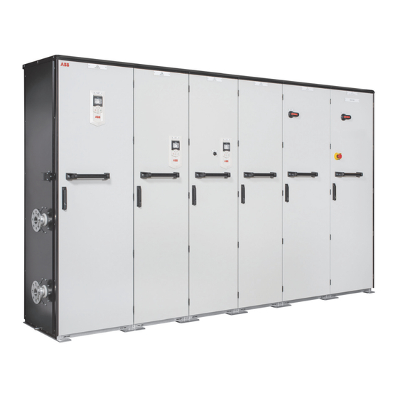
- Page 1 — ABB INDUSTRIAL DRIVES ACS880 liquid-cooled multidrive cabinets Mechanical installation instructions...
- Page 3 ACS880 liquid-cooled multidrive cabinets Mechanical installation instructions Table of contents 1. Mechanical installation © 2019 ABB Oy. All Rights Reserved. 3AXD50000048635 Rev A EFFECTIVE: 2019-06-30...
-
Page 5: Table Of Contents
Table of contents 5 Table of contents 1 Mechanical installation Contents of this chapter ................Examining the installation site ..............Necessary tools ................... Checking the delivery ................Moving and unpacking the drive ..............Moving the drive in its packaging ............Lifting the crate with a forklift ............. -
Page 7: Mechanical Installation
Mechanical installation 7 Mechanical installation Contents of this chapter This chapter describes the mechanical installation procedure of the drive. Examining the installation site Examine the installation site: • The installation site is sufficiently ventilated or cooled to remove heat from the drive. See the technical data. -
Page 8: Checking The Delivery
8 Mechanical installation Checking the delivery The drive delivery contains: • drive cabinet line-up • optional modules (if ordered) installed onto the control unit(s) at the factory • appropriate drive and optional module manuals • delivery documents. Check that there are no signs of damage. Before attempting installation and operation, check the information on the type designation labels of the drive to verify that the delivery is of the correct type. -
Page 9: Moving And Unpacking The Drive
Mechanical installation 9 Moving and unpacking the drive Move the drive in its original packaging to the installation site as shown below to avoid damaging the cabinet surfaces and door devices. When you are using a pallet truck, check its load capacity before you move the drive. The drive cabinet is to be moved in the upright position. -
Page 10: Lifting The Crate With A Crane
10 Mechanical installation Lifting the crate with a crane Lifting point Optimal position for the lifting sling: as close to the traverse board as possible... -
Page 11: Moving The Crate With A Forklift
Mechanical installation 11 Mechanical installation 61 Moving the crate with a forklift Moving the crate with a forklift 750 mm (29.5'') ■ Removing the transport package Remove the transport package as follows: 1. Undo the screws that attach the wooden parts of the transport crate to each other. 2. -
Page 12: Moving The Unpacked Drive Cabinet
1. Undo the screws that attach the wooden parts of the transport crate together. 2. Remove the wooden parts. 3. Remove the clamps with which the drive cabinet is mounted onto the transport pallet 12 Mechanical installation by undoing the fastening screws. 4. -
Page 13: Moving The Cabinet On Rollers
Mechanical installation 13 Moving the cabinet on rollers WARNING! Do not move marine versions (option +C121) on rollers. Lay the cabinet on the rollers and move it carefully until close to its final location. Remove the rollers by lifting the unit with a crane, forklift, pallet truck or jack. Moving the cabinet on its back WARNING! Do not transport the drive with an LCL or L filter on its back. -
Page 14: Final Placement Of The Cabinet
14 Mechanical installation Final placement of the cabinet Move the cabinet into its final position with a slate bar (spud bar). Place a piece of wood between the edge of the cabinet and the bar to protect the cabinet frame. -
Page 15: Fastening The Cabinet To The Floor And Wall Or Roof
Mechanical installation 15 Fastening the cabinet to the floor and wall or roof ■ General rules • The drive must be installed in an upright vertical position. • Leave 250 mm (9.85”) of free space above the cabinet for maintenance, and to allow pressure relief operation. -
Page 16: Fastening The Cabinet (Non-Marine Units)
16 Mechanical installation ■ Fastening the cabinet (non-marine units) Alternative 1 – Clamping 1. Insert the clamps (included) into the twin slots along the front and rear edges of the cabinet frame body and fasten them to the floor with a bolt. The recommended maximum distance between the clamps in the front edge is 800 mm (31.5”). -
Page 17: Alternative 2 - Using The Holes Inside The Cabinet
Mechanical installation 17 Alternative 2 – Using the holes inside the cabinet 1. Fasten the cabinet to the floor through the bottom fastening holes with M10 to M12 (3/8” to 1/2”) bolts. The recommended maximum distance between the front edge fastening points is 800 mm (31.5”). -
Page 18: Fastening The Cabinet (Marine Units)
18 Mechanical installation ■ Fastening the cabinet (marine units) See the dimension drawing delivered with the drive for details of the fastening points. Fasten the cabinet to the floor and roof (wall) as follows: 1. Bolt the unit to the floor through the flat bars at the base of the cabinet using M10 or M12 screws. -
Page 19: Joining Cabinet Sections Together
Mechanical installation 19 Joining cabinet sections together Wide cabinet line-ups are delivered in multiple sections. The sections are to be joined on-site using a 200 mm wide joining cubicle at the end of one section (a common motor terminal cubicle can also act as a joining cubicle). The screws required for the joining are enclosed in a plastic bag inside the cabinet. - Page 20 20 Mechanical installation 5. Center the Axilock connectors onto the gaps between coolant pipe ends. Tighten the connector screws to the torque indicated on the connector label. 6. Fasten the front and rear posts of the joining cubicle to the posts of the other section with 14 screws (7 per post).
- Page 21 Mechanical installation 21 9. Remove the shroud covering the DC busbars in the joining cubicle. 10. Use the joint pieces to connect the DC busbars. Tighten the bolts to 55…70 N·m (40…50 lbf·ft). Units with single DC busbars 55…70 N·m 55…70 N·m (40…50 lbf·ft) (40…50 lbf·ft)
-
Page 22: Miscellaneous
■ Arc welding ABB does not recommend attaching the cabinet by arc welding. However, if arc welding is the only option, connect the return conductor of the welding equipment to the cabinet frame at the bottom within 0.5 meters (1’6”) of the welding point. -
Page 23: Further Information
Product and service inquiries Address any inquiries about the product to your local ABB representative, quoting the type designation and serial number of the unit in question. A listing of ABB sales, support and service contacts can be found by navigating to www.abb.com/searchchannels. - Page 24 3AXD50000048635A © 2019 ABB Oy. All Rights Reserved. Specifications subject to change without notice.
Need help?
Do you have a question about the ACS880 and is the answer not in the manual?
Questions and answers