
Related Manuals for socomec ATyS UL 1008


Summary of Contents for socomec ATyS UL 1008
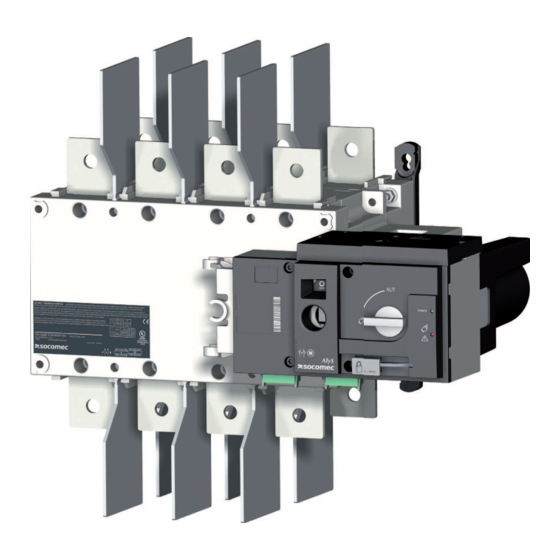
- Page 1 ATyS UL 1008 Transfer Switching Equipment www.socomec.com www.socomec.com/operating-instructions To download, brochures, catalogues and technical manuals.
-
Page 2: Table Of Contents
INDEX 1. GENERAL SAFETY INSTRUCTIONS ............4 2. - Page 3 5.4.3. MOUNTING OF ADDITIONAL AUXILIARY CONTACTS FOR 100 TO 400A (OPTIONAL ACCESSORIES) . . .23 5.4.4. POWER TERMINAL CONNECTIONS (OPTIONAL ACCESSORIES) ......24 .
-
Page 4: General Safety Instructions
1. GENERAL SAFETY INSTRUCTIONS This instruction manual must be made accessible so as to be easily available to anyone who may need to read it in relation with the AT The AT Do not handle any control or power cables connected to the ATYS when voltage may be present on the product directly through the mains or indirectly through external circuits. -
Page 5: Introduction
2. INTRODUCTION AT S transfer switches are designed for use in total system optional standby power applications for the safe ATYS transfer switching equipment ensures: (Manual operation is functional with and without the motorization in place). Genset Genset ATyS ATyS ATyS... -
Page 6: Quick Start
This Quick Start is intended for personnel trained in the installation and commissioning of this product. For further details refer to the product instruction manual available on STEP 4 the SOCOMEC website. This product must always be installed and commissioned ■ by qualified and approved personnel. -
Page 7: Bridging Bars (Optional Accessory)
STEP 1B 0.83in 21mm Dimensions in/mm Ref. code mm in mm in mm in mm in mm in mm in mm in mm in mm in mm in mm in mm in mm in mm in mm in mm in mm in mm 2/3P 12.91 328 6.30 160 6.30 160 9.60 244 0.41 10,5 5.08 129 6.8 173 4.21 107... - Page 8 3.1. Quick Start ATY STEP 2B Power Terminal Connections (optional accessories) To be connected using terminal lugs, rigid or flexable busbars. FRAME B4 FRAME B5 100 A 200 A 260 A 400 A Ref ATyS 97232010 97233010 97234010 97232020 97233020 97234020 97232026 97233026 97234026 97232040 97233040 97234040 Ref lugs 39542020 39543020 39544020 39542020 39543020 39544020 39542040 39543040 39544040 39542040 39543040 39544040 Qty per reference...
- Page 9 STEP 3B CONTROL / COMMAND Terminals - Ensure that the product is in Manual Mode. Class CC 4A fuse 312 313 314 315 316 317 63A 64A 24 14 04 13 CONTROL OUTPUTS Connect the product with a cable of section of 24 to 16 AWG. Screw M3 - Tightening torque: min.: 5 lb-in - max.
- Page 10 This Quick Start is intended for personnel trained in the installation and commissioning of this product. For further details refer to the product instruction manual available on Clip for the SOCOMEC website. storage of ■ This product must always be installed and commissioned by qualified and approved personnel.
- Page 11 1.96 3.54 Dual Dimensions STEP 1B Ø 0.41 Ø 10,5 0.98 1.02 1.49 1.02 Ø 0.41 Ø 10,5 0.83 Ref. code 3P 19.8 13.38 340 15.4 9.09 13.7 9.05 11.5 2.02 51.5 9.84 4.92 3.15 2.61 66.5 9.98 4P 22.99 584 13.2 3P 23.5 13.7...
-
Page 12: Mounting Of Terminal Covers (Optional Accessory)
3.2. Quick Start ATY STEP 2B Power Terminal Connections (optional accessories) To be connected using terminal lugs, rigid or flexable busbars. FRAME B6 FRAME B7 600 A 800 A 1200 A Ref ATyS 97233060 97234060 97233080 97234080 97233120 97234120 Ref lugs 39543060 39544060 39543080... - Page 13 STEP 3B Control / Command Terminals - Ensure that the product is in Manual Mode. Class CC 4A fuse 312 313 314 315 316 317 63A 64A 24 14 04 13 CONTROL OUTPUTS Connect the product with a cable of section of 24 to 16 AWG. STEP 4 Power Supply Terminal - Remove the Top cover to access and connect the terminal - Replace the cover before putting in service.
- Page 14 GENERAL OVERVIEW Product introduction (Position indication I-O-II and product availability outputs)
- Page 15 Electrical characteristics Applicable standards and...
- Page 16 Environmental The AT S product meets the following environmental requirements: ø 1 mm Operating Conditions Temperature Altitude Storage Conditions Temperature 100 - 400A 600 - 1200A...
- Page 17 Volume and shipping weights by reference ATYS N° of Reference Frame Size Number Gross UL marking The AT S complies the with the European directive for: The AT...
- Page 18 INSTALLATION 21mm Rating Ref. code in mm in mm in mm in mm in mm in mm in mm in mm in mm 97232010 / 97233010 / 97232020 / 97233020 2/3P 12.91 328 100 - 200A 6.30 160 9.60 244 0.41 10,5 5.08 129 6.8 173 4.21 107 1.51 38,5 5.21 132,5 97234010 / 97234020 4P 14.88 378 97232026 / 97233026 / 97232040 / 97233040...
- Page 19 1.96 3.54 Ø 0.41 Ø 10,5 0.98 1.02 1.49 1.02 Ø 0.41 Ø 10,5 0.83 Ref. in mm in mm in mm in mm in mm in mm in mm in mm code 3P 19.8 13.38 340 15.4 392 9.09 231 13.7 347 9.05 230 11.5 293 2.02 51.5 9.84 250 4.92 125 3.15 2.61 66.5 9.98 254...
- Page 20 Mounting orientation CAUTION Always install the product on a flat and rigid surface. Assembly of customer mounted accessories Never handle any customer mounted accessories while there may be the risk of DANGER voltage being or becoming present.
- Page 21 USED FOR ATYS REF. USED FOR ATYS REF. USED FOR ATYS REF. USED FOR ATYS REF. USED FOR ATYS REF.
- Page 22 13.3 lb-in 1,5 Nm pozidriv n°1 Ref. USED FOR 22 lb-in 2,5 Nm Flat 5 USED FOR...
- Page 23 Mounting of terminal covers USED FOR (optional accessory) 22 lb-in 2,5 Nm Flat 5 Pos II P o s Pos II Pos I 1 (fast-on) General Use 1A P o s Pos I...
-
Page 24: Power Terminal Connections (Optional Accessories)
To be connected using terminal lugs, rigid or flexable busbars. FRAME B4 FRAME B5 100 A 200 A 260 A 400 A Ref ATYS 97232010 97233010 97234010 97232020 97233020 97234020 97232026 97233026 97234026 97232040 97233040 97234040 Ref lugs 39542020 39543020 39544020 39542020 39543020 39544020 39542040 39543040 39544040 39542040 39543040 39544040 Qty per reference Ref qty to order... - Page 25 Power Terminal Connections (optional accessories) To be connected using terminal lugs, rigid or flexable busbars. FRAME B6 FRAME B7 600 A 800 A 1200 A Ref ATyS 97233060 97234060 97233080 97234080 97233120 97234120 Ref lugs 39543060 39544060 39543080 39544080 39543120 39544120 Qty per reference Ref qty to order...
-
Page 26: Typical Atys Wiring (480/277 Vac)
Control circuits Verify that the nominal auxiliary power supply feeding terminals 301 and 302 are CAUTION within the limits of 208VAC -> 277VAC Do not handle any control or power cables connected to the ATYS when voltage DANGER may be present. Typical ATY Class CC 4A fuse... -
Page 27: Atys Input And Output Contacts
ATYS input and output contacts Denomination Terminal Description Characteristics Recommended Cable Section Signalisation Outputs (No Fault powered and ready to changeover) Power supply Input Control Inputs input forcing the product to remote control mode Attn: Do not connect terminals 312 to 317 to any power supply. These order inputs are CAUTION powered through terminal 317 and external dry contacts ONLY. - Page 28 ATYS OPERATING MODES The AT As standard the AT The modes of operation are as follows: Activates the remote control manual operation handle when padlocked or when the handle for manual operation is inserted into the AT Allows to insert the handle (With the handle for manual operation removed) Turning the selector switch to...
- Page 29 Manual operation The AT To operate the AT CAUTION Ensure to verify the product position and direction of rotation before effecting manual Ensure to remove the handle from the product before turning the selector switch back towards Padlocking The AT To padlock the AT Padlocking is only made possible in the “O position”, when in manual mode and CAUTION...
-
Page 30: Power Supply
Electrical operation Power supply within the limits of : Fixed inputs Description The AT The AT Pin 312: Pin 313: contact is open the AT This contact is active with the AT This contact is active with the AT This contact is active with the AT... - Page 31 Motorisation Module Thighten torque: Impulse logic: Impulse logic order I The AT order 0 order II position I position 0 position II Contactor logic order I The AT order 0 order II position I position 0 (1st order received is held until no longer maintained).
-
Page 32: Fixed Outputs - Dry Contacts
Fixed outputs - Dry contacts Description The AT This contact gives constant feedback about the product’s availability and it’s capacity to transfer from the main The AT S motorisation module become Conditions that render the Comments Relay ATyS motorisation unavailable Manu Open LED ON... - Page 33 Startup duration minimum minimum Thighten torque:...
- Page 34 Frame size Short circuit rating at 600 VAC with fuses (kA) Type of fuse Short circuit rating at 600 VAC with "Specific Circuit Breaker" (kA) Short circuit rating at 600 VAC with "Any Breaker" (kA) Rated operational current Connection terminals Power supply Switching time...
- Page 35 PREVENTIVE MAINTENANCE of the critical level and application where the product is installed should form an essential and integral part of the The AT S does not operate electrically manually operate the switch Electrical operation does condition switch the AT...
- Page 36 YS FAMILY The AT The AT S will depend on the application as well as the nature of installation in which the AT all other AT (The encircled device is the product detailed in this instruction manual). Transformer Side by Side ATyS The ATYS Range Key Features Selecting the right AT...
- Page 37 ATyS ATyS ATyS ATyS ATyS ATyS ATyS ATyS Test on load functionality Test off load functionality...
- Page 38 11. ATYS Family: ORDERING INFORMATION The following is an ordering guide for AT Product Type Ctrl Voltage N° of poles Rating Note Product Type Ctrl Voltage N° of poles Rating Note...
- Page 40 CORPORATE HQ CONTACT: SOCOMEC SAS 1-4 RUE DE WESTHOUSE 67235 BENFELD, FRANCE www.socomec.com...
Need help?
Do you have a question about the ATyS UL 1008 and is the answer not in the manual?
Questions and answers