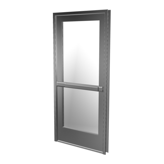
Summary of Contents for C.R. Laurence CRL JACKSON 1295
- Page 1 INSTALLATION INSTRUCTIONS CRL JACKSON 1295 RIM PANIC EXIT DEVICE Phone: (800) 421-6144 • Fax: (866) 921-0531 crlaurence.com • usalum.com • crl-arch.com crlaurence.com 11M0249...
- Page 2 CRL JACKSON 1295 RIM PANIC EXIT DEVICE ORDER OF ASSEMBLY AND INSTALLATION Tools Required ...................
- Page 3 CRL JACKSON 1295 RIM PANIC EXIT DEVICE PARTS IDENTIFICATION FASTENERS PROVIDED CALL FASTENER USED WITH QTY. FASTENER PART DESCRIPTION PART NUMBER 3/16" Pan Head 302670 Screw Dogging Assembly Base End Plate 1/4"-20 x 1/2" (Included in 302654 Pan Head SMS Base Cover Plate Pkg.)
- Page 4 CRL JACKSON 1295 RIM PANIC EXIT DEVICE PARTS IDENTIFICATION PARTS LIST CALL QTY. PART PART NO. DESCRIPTION 302674 and Cover Plate 30267448 Optional Rim DL911 Key Cylinder "C" Type Surface 302436 Mounted Strike "S" Type Surface 302501 Mounted Strike 9500LV02...
- Page 5 CRL JACKSON 1295 RIM PANIC EXIT DEVICE DOOR PREPARATION REMOVE DOOR 1. Place door horizontally on stands, interior side up. 2. Mark stile centerlines Y-lines, 1-1/8" (28.6) from outside edge for all stile widths. (Fig. 1) 3. Mark stile X-lines per template instructions. (Fig. 2) 4.
- Page 6 CRL JACKSON 1295 RIM PANIC EXIT DEVICE DOOR PREPARATION – LAYOUT SELECTION 1295 RIM PANIC EXIT DEVICE INSTALLATION INTERIOR VIEW 1295 ACTIVE STILE ACTIVE STILE MOUNTING INSIDE FACE Drill and Countersink for a 10-32 FHMS (2) Places Drill and Tap for 12-24 FHMS (2) Places Drill 9/16"...
- Page 7 CRL JACKSON 1295 RIM PANIC EXIT DEVICE DOOR PREPARATION – LAYOUT SELECTION 1295 RIM PANIC EXIT DEVICE INSTALLATION WITH OPTIONAL RIM LOCK CYLINDER INTERIOR VIEW 1295 ACTIVE STILE ACTIVE STILE MOUNTING INSIDE FACE For Cylinder Only Drill 7/32" (5) (2) Places...
- Page 8 CRL JACKSON 1295 RIM PANIC EXIT DEVICE DOOR PREPARATION – LAYOUT SELECTION 1295 RIM PANIC EXIT DEVICE INSTALLATION WITH OPTIONAL EXTERIOR TRIM AND RIM CYLINDER INTERIOR VIEW Drill and Countersink for a 10-32 FHMS ACTIVE STILE (2) Places 1295 ACTIVE STILE MOUNTING INSIDE Drill 9/16"...
- Page 9 CRL JACKSON 1295 RIM PANIC EXIT DEVICE DOOR HARDWARE INSTALLATION INSTALLATION OF OPTIONAL RIM CYLINDER NOTE: Optional Rim Cylinder must be installed before attaching exit device. Attach the Rim Cylinder on door stile with (2) 1-7/8" (47.6 mm) Breakaway Screws provided. Fig. 9...
- Page 10 CRL JACKSON 1295 RIM PANIC EXIT DEVICE DOOR HARDWARE INSTALLATION (CONTINUED) INSTALLATION OF EXTERNAL TRIM (OPTIONAL) NOTE: Exterior trim must be installed before attaching exit device. Attach the exterior trim with (2) #10 x 2-1/8" Flat head screws provided shown in Fig. 10.
- Page 11 CRL JACKSON 1295 RIM PANIC EXIT DEVICE DOOR HARDWARE INSTALLATION (CONTINUED) INSTALLATION OF 1295 RIM PANIC EXIT DEVICE Attach exit panic device to door with (2) 12-24 x 3/4" FHMS on active stile and (1) 1/4"-20 x 1/2" PHSMS at end cap bracket on inactive stile as shown in Fig. 11.
- Page 12 CRL JACKSON 1295 RIM PANIC EXIT DEVICE DOOR HARDWARE INSTALLATION (CONTINUED) INSTALLATION OF END CAPS AND COVER PLATES Slide the (2) base cover plates 302674 and 30267448 in place. Attach both end caps to the previously attached end cap brackets with (4) 8-32 x 1/4"...
- Page 13 CRL JACKSON 1295 RIM PANIC EXIT DEVICE DOOR HARDWARE INSTALLATION (CONTINUED) FRAME PREPARATION Apply Dogging 1/4"-20 Instruction Label Tap Hole to back of Cover Inactive Stile (2) 8-32 x 1/4" Active Stile FHMS EXTERIOR Base Cover Plate (2) 10-24 x 5/8"...
- Page 14 CRL JACKSON 1295 RIM PANIC EXIT DEVICE DOGGING INSTRUCTIONS TO DOG Insert Hex Dogging Key (Cat. No. 302796). Turn Key clockwise until it stops. Depress and hold the Push Bar then release the Key. Push Bar will remain depressed. Remove Key. (Fig. 14) TO UNDOG Insert Hex Dogging Key and turn clockwise until it stops.
- Page 15 CRL JACKSON 1295 RIM PANIC EXIT DEVICE PACKAGED PARTS AVAILABLE Assembly No. Part No. Description 302654 Base End Cap Package 302679 Latch Assembly Package 302664 Control Arm Hardware Package 302670 Dogging Assembly 302650 Push Pad End Cap Package 302674 Cover Plate Package - Ribbed - 3/0 Panic...

Need help?
Do you have a question about the CRL JACKSON 1295 and is the answer not in the manual?
Questions and answers