Table of Contents
Advertisement
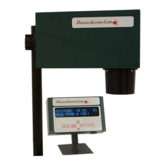
Multiple Constituent Transmitter
Installation and Operation Manual
USA:
Process Sensors Corp
113 Cedar Street, S1
Milford, MA 01757
Tel: (508) 473-9901
Fax: (508) 473-0715
info@processsensors.com
MCT Series
June 15, 2005
Process Sensors Corporation
www.processsensors.com
Europe:
Process Sensors Europe
Adelaide House, Unit 3
Corbygate Business Park
Corby, Northants NN17 5JG UK
Tel: (44) 015 36408066
Fax: (44) 015 36407813
infouk@processsensors.com
Eastern Europe:
Process Sensors Polska
Dr inz. Tomasz Stachowiak
Biuro Informatcyjne Techniki
Pomiarowej 03-980 Warzawa
ul. Znanieckiego 16/23
Tel: (48) 226739526
Fax: (48)226739527
T_stachowiak@poczta.onet.pl
Advertisement
Table of Contents

Summary of Contents for Process Sensors MCT Series
- Page 1 Multiple Constituent Transmitter MCT Series Installation and Operation Manual June 15, 2005 Process Sensors Corporation www.processsensors.com Eastern Europe: Process Sensors Polska USA: Europe: Dr inz. Tomasz Stachowiak Process Sensors Corp Process Sensors Europe Biuro Informatcyjne Techniki 113 Cedar Street, S1...
-
Page 2: Table Of Contents
Table of Contents Introduction Main Menu Selections Principle of Operation Sensor Components On-Line Menu 3. 1 Light Source Calibration Parameters Filter Wheel 7.4.1 Analog Output Channels Filter Wheel Motor Calibration Routine Detector Diagnostics Electronics Miscellaneous Installation Gauge Calibration 4. 1 Sitting the Sensor 8. - Page 3 Warranty, Exclusions and Limitations The workmanship and the materials of all products manufactured by Process Sensors Corp. are warranted for a period of one year from the date of shipment. This warranty covers parts and labor required to correct defects within the scope of the Corporation’s warranty.
-
Page 4: Introduction
1.0 Introduction The MCT Series are near infrared photometric analyzers that use fixed infrared wavelengths to measure one, two or three constituents in a variety of products. The MCT is a “stand-alone” sensor with all items necessary for continuous monitoring being located in the sensor. -
Page 5: Electronics
3.5 Electronics The MCT contains the following electronic components: o Power Supply, a 90-260 volt auto selection supply providing DC power to operate the sensor. o Main PCB, containing pre-amplifiers, detector controller, central processing system, analog and serial communications. 4.0 Installation 4. -
Page 6: Reflections From Material Surface
The optimum viewing distance is 8” (200mm) from the bottom of the sensor but any distance between 6” and 12” (150 - 300mm) is acceptable. Variations in product pass height of +/- 1” (25mm) around the 8’’ (200mm) nominal are permissible. 4.7 Reflections from the Material Surface It is essential to avoid specular reflections of the transmitted light from the product. -
Page 7: Ac Power Connections
Refer to Section 11.0 5. 1 AC Power Connection The sensor is powered directly using the 6-foot (2mtrs) power cord provided. The input is auto ranging and accepts 90-260VAC volts, 15 amps. It is recommended that the power be supplied via a breaker or on/off switch mounted close to the sensor. -
Page 8: Wall Mounting Interface
6.1 Wall Mounting Interface The Wall Operator Interface is a display unit with keypad for user setup, calibration and routine interaction with the sensor. It is constructed in a cast aluminum housing rated for Nema 12 (IP 55). The display is a two-line 20 character vacuum fluorescent display. It may be mounted up to 100 feet from the sensor and obtains both power and communications from the sensor. - Page 9 Wall Mount Operator Interface...
-
Page 10: Keypad
Keypad Keys: Symbol: Allows the user to move around the menu structure and to position the cursor UP/DOWN in the desired place for setting numerical RIGHT/LEFT values. Selects the desired Product Calibration PRODUCT Code. CODE Confirms changes and commits them to ENTER permanent memory. - Page 11 Operator Interface Panel...
-
Page 12: Set-Up Instructions-Operator Interface
7.1.1 Keypad Lock The complete keypad may be ‘locked’ preventing use of any key until the correct key push sequence is made to unlock the keypad. Contact Process Sensors to obtain the lock and unlock sequences. 7.1.2 Display Selector The MCT may be ‘Set-up’... - Page 13 Constit 1 : 3.6% Constit 2 : 25.9% Home Screen for Three Constituents Constit 1 : 3.6% Prod.: Prod A (01) In the Three Constituent Mode the top line will scroll through the three constituents at 5-second intervals. An asterisk will be presented in the upper right corner indicating that the sensor is in the Three Constituent Mode.
- Page 14 Dual Mode Pressing Display Rotate a third time will Constit 1: 3.6% revert the display to the Constit 2: 25.9% two constituent 'home screen' Triple Mode Pressing the Display Constit 3: 34.5% Rotate a third time will Prod: Prod A (01) select the third constituent menu Pressing Display...
- Page 15 Moisture: 3.6% 01 Home Screen-Single Mode Prod: Prod A (01) Press the code # key Moisture: 3.6% 01 will scroll through the Prod.: Prod A (09) ??? 10 product codes Moisture: 3.6% 01 Press ENTER to accept New Cal Accepted the desired Prod.
-
Page 16: Main Menu Selections
Press the Grab Sample key a third time to exit the routine or wait 10 seconds and it will exit automatically. Press Display Rotate to return to the ‘Home’ screen. 7.2. Main Menu Selections The menu selections of each constituent are as follows: Online (Home) Calibration Parameters Calibration Routine... - Page 17 Main Menu Selections Home Moisture: 12.89% Moisture: 12.89% Prod.: Prod A (01) Damping: 5 Moisture = 5.1% 01 Sample Val: 0.0 Moisture: 12.89% Moisture: 12.89% CAL PARAMETERS Password:0000 Displays Calibration Parameters Moisture: 12.89% Moisture: 12.89% CAL ROUTINE Password:0000 Enters Cal Develop Moisture: 12.89% Moisture: 12.89% DIAGNOSTICS...
-
Page 18: On-Line Menu
7.3 On-line Menu The user may make changes to the response time of the sensor and to the zero setting of the selected Calibration Channel directly from the ‘Home” screen. When at the ‘home’ screen, pressing the RIGHT arrow will display the Damping Time currently being used by the sensor. -
Page 19: Calibration Parameters
7.4 Calibration Parameters Move down to display CAL Parameters Moisture= 12.89% Move right to enter the CAL Parameters menu Password: Move cursor under digits, Moisture= 12.89% Moisture= 12.89% move up/down to set the correct PASSWORD=0000 PASSWORD=____ password, Press ENTER to accept Prod. - Page 20 Analog Ranges: Move down to access the Analog Output Ranges. Analog Out 1 High Setting: Move the cursor under the Moisture= 12.89% Moisture= 12.89% value. Move up/ Anout (1) HI: 100.0 Anout (1) HI: 50.00 down to set the desired value, press Enter to confirm.
-
Page 21: Analog Output Channels
7.4.1 Analog Output Channels The MCT has three analog output channels providing both milliamps and voltage signals. These channels may be designated to the constituent using an RS 232 command. The default designations are as follows: Single Constituent Mode Format Constituent # Analog 1 Isolated... - Page 22 This menu selection allows the operator to correctly calibrate the sensor on the range of products being measured. When using this sequence, the following information will be required: Calibration Channel (1 through 9) that was used to generate the MCT readings for each sample.
- Page 23 Move the cursor under the Prod. Code value and scroll up/down to set the correct value. Press Enter to accept. Move DOWN to enter the first data value. Moisture= 12.89% Moisture= 12.89% Start: PROD A (01) Start: PROD A (03) Move the cursor under the digits for the first LAB value.
- Page 24 Regression Statistics: The display will present the linear regression statistics of correlation coefficient CC and standard error SE. Move down. Moisture= 12.89% CC:0.987 SE: 0.04 Calculated Calibration Settings: Using the regression statistics, the software will calculate the correct calibration settings for the data entered. Move down from the zero screen to view the Span value. Moisture= 12.89% New Zero: -23.56 Moisture: 5.1% 01...
-
Page 25: Diagnostics
.6 Diagnostics The MCT’s software continually monitors several internal electronic variables to ensure that the sens is operating correctly at all times. If any of these parameters go out of pre-set limits then the M CT’s display will provide a warning message. Maintenance perso nnel may view the values of these arameters by selecting Diagnostics from the Main Menu. - Page 26 Moisture = 12.89% This is the motor speed in rpm. Motor: 1101 rpm Moisture = 12.89% This is the value of the +5 volt power PSU VCC: +4.9v supply. Moisture = 12.89% This is the value of the +15 volt power PSU VP: +15.3v supply.
-
Page 27: Miscellaneous
Ranges of Diagnostic Parameters: The Operator Interface Display will present fault warnings indicating that certain diagnostic values are outside of the acceptable ranges. The following table gives the range of values for each of the diagnostic parameters and the fault message that is displayed on the Operator Interface. Parameter Nominal Min. - Page 28 This menu selection allows users to setup several basic parameters and to view some reference data stored in the sensors memory. Press RIGHT to enter the menu. Press RIGHT again to move the cursor under the digits, Scroll up/down to set the correct password. Moisture = 12.89% Moisture = 12.89% MISCELLANEOUS...
- Page 29 Enter a new password as above. The characters that may be used in the password are 0-9. The MCT series sensors arre fitted with software that continually monitors the cleanliness of the sensor window. This software may be switched ON/OFF by this Moisture = 12.89%...
-
Page 30: Gauge Calibration
8.0 Gauge Calibration The object of gauge calibration is to obtain a straight-line graphical relationship between the sensor’s reading and the true moisture value of a series of samples. Calibration Graph True Moisture 8. 1 Approximate Calibration Select one of the Product Codes (1-9 or 1-50) that will be used to store the calibration setting for the product being measured. -
Page 31: Multi-Sample Calibration
8. 2 Multi-Sample Calibration- Static Samples A more accurate calibration may be obtained by using a larger quantity of samples. As for the approximate calibration, select the Product code that will be used to store the correct calibration settings. Make or collect from the process a series of sample (up to 25) with moisture contents covering the range expected in the process. -
Page 32: On-Line Off Set Trim Adjustments
8.3 On-line Offset Trim Adjustment Install the sensor on the moving process line. Grab 2-3 samples of the product and note the sensor’s reading for each sample. For a more accurate calculation of the sensor’s readings during the collection of the each sample, the sensor’s “grab sample average feature” may be used. Refer to section 7.3 for more details on the use of this feature. - Page 33 Sample Handling: Representative sampling is a key factor in the calibration procedure. It must ensure that any sample taken from the line relates exactly to the displayed moisture reading logged as “the sensor reading”. Samples should be taken immediately downstream of the sensor and in the same plane as the measurement beam.
-
Page 34: Accessories
9.4 Cooling Panels The MCT series sensors may be fitted with a cooling panel to allow the sensor to be installed in environments where the temperature is greater than 50 C (120 F). -
Page 35: Maintenance Alarm
9.5 Maintenance Alarm The MCT sensor may be fitted with an alarm card with a DC solid-state relay that will activate whenever any of the sensor’s internal alarms are triggered. Refer to the Maintenance Section for a listing of the alarms that will trigger the alarm contact. 9.6 Dirty Window Alarm All MCT sensors have a software routine that continually monitors the cleanliness of the sensor’s window. -
Page 36: Output Signals
10.0 Output Signals The MCT has the following signal interfaces available for connection to other devices. Three 0–10 volts isolated. Analog Outputs: Three 4-20mA isolated. Load resistance 500 ohms Max. Hold/Gated Input: Facility for a contact closure input indicating a gap in the stream of product on the conveyor. - Page 37 MCT300 RS485 QUICK START GUIDE EXAMPLE OF RS485 CONNECTION TO MCT SERIES +12V 485 A (IN) TD(B) 485 B (IN) TD(A) FIRST SENSOR ALL 3 JUMPERS MUST BE PLACED ON LAST SENSOR IF HOST PC DOES NOT HAVE PULLUPS PULLDOWNS.
- Page 38 Example of connecting a B&B RS485 Converter to the MCT300 OI connector.
-
Page 39: Customer Wiring Connections
11.0 Customer Wiring Connections All wiring connections are made to three quick-disconnect connectors mounted on the rear of the sensor enclosure. These connectors may have different signals coming to them from inside the sensor. The following diagrams show the standard configurations for these connectors. POWER Terminal Input... - Page 40 DIGITAL Connector (RS232, RS485 & Hold) – Standard Configuration Terminal # Signal RS485 A RS485 B RS232 Tx RS232 Rx Digital Gnd Hold Input Note: When sensors are fitted with network interface cards this Digital connector may be wired to meet the network format or it may be replaced with the network’s approved connector.
- Page 41 Rear of Sensor...
- Page 42 Rear Analog/Digital Connector Use the end of the Dust Cover to un-screw the ‘Retaining Ring’ in order to remove the 6 pin connector. The ‘Flat part’ of the connect fits into the ‘Housing’, mating with a similar ‘Flat part’.
-
Page 43: Maintenance
12.0 Maintenance Tools required for maintenance on the MCT sensor and Operator Interface are: Flat blade screwdriver 7/64” Allen Key 3/32” Allen Key 5/64’ Allen key 1/16” Allen Key 12.1 Routine Maintenance The MCT requires little or no routine maintenance. 12.1.1Sensor Window The ‘Clean Window Software’... -
Page 44: Corrective Maintenance
Screen Message Description Corrective Action High Signals Too much signal Check for proper product placement or no product Low Signals Too little signal Check for proper product placement or no product High Motor Speed Motor rpm above 1200 Call PSC Low Motor Speed Motor Speed below 1000 Call PSC... - Page 45 MCT Enclosure The MCT sensor has two-part cast aluminum housing. The two sections are held together by four machine screws. These screws are held captive in the bottom half of the housing. Unscrew the four screws and place the upper half to one side. Lamp Replacement This operation requires that the optical bench be removed from the bottom half of the sensor enclosure.
- Page 46 9. Install the new motor; connect it to the main board. 10. Re-install the dome mirror/detector plate assembly and re-connect the detector to the main board. 11. Re-connect the power supply harness and the power supply assembly to the main board. 12.
- Page 47 8. Install a new power supply on the plate. Make sure the insulating paper is fitted under the power supply. 9. Re-connect the power supply harness and the power supply assembly to the main board. 10. Re-connect the AC cable to the power supply. 11.
-
Page 48: Replacement Parts List
Replacement Parts List 12.4 Sensor Description 300035-2 Main Board (A1149) 200025 Power Supply (GPC408) 200022A Detector Assembly 200019A Lamp Assembly 200056 Motor Assembly 200013 Dome Mirror 200010A Sensor OI Cable Connector Assembly 300027A Analog I/O Connector Assembly 300028A Digital I/O Connector Assembly 300002A Power Connector Assembly 300030... - Page 49 Wall Operator Interface Description 210002 Display Module (IEE) 210040 Interface Board (IEE) 210008 Cable Connector Assembly 210041 Keypad Board 210021 Display Module (Graphic) 210023 Graphic Display Interface PCB...
-
Page 50: Special Features
Appendix 1 – Special Features Backdoor Password If the password for the MCT has been forgotten is unknown then a special ‘backdoor’ password will allow the user/engineer to view and change the old password. To use this ‘backdoor’ system proceed as follows: Press Display Rotate to present a single constituent Home screen. - Page 51 Access to the Engineering Menu is gained by using a special password. At any password request enter the number 2882 and press ENTER. This will allow access to the menu. Preamp Gain The MCT has a software adjustable preamp gain factor. This factor is the gain applied to the filter signals coming from the detector.
- Page 52 To change a value, move the cursor under the number and scroll up/down to set a new value. Press ENTER to save this value Moisture = 12.89% 01 The first constituent will use the measure filter F1 C1: 1.0 and will thus have C1=1 and C6=0.0 the coefficients for C2-C5 will variable, depending on the application of the sensor.
- Page 53 Math Code Moisture: 3.3% 01 Linear Algorithm (1=Log): 0 Press Enter to save Instrument Network ID # Moisture: 3.6% 01 This line allows each sensor to be Inst ID: 1 given a discrete number, when multiple sensors are connected using RS485. Main Board Serial # Moisture: 3.6% 01 This lists the serial number of the...
- Page 54 Dual Mode Moisture: 3.6% 01 The MCT May be switched Single Dual: Y/N to Dual Mode. The triple mode requires a different EPROM to be fitted to the sensor. Language Selection Moisture: 3.6% 01 The MCT display system may be set to use a different language to Language: Y/N English.
- Page 55 Averaging Modes The MCT 300 has a choice of three methods of ‘averaging’ the constituent readings, these are: Damping: This is a time constant based ‘smoothing’ of the readings. Real Time Averaging: This is a ‘pipeline’ average of the readings over a selected time. Gated: This is an ‘event’...
- Page 56 Dead Band The MCT has built-in Smoothing Factor that operates at a +/- level Moisture: 3.6% 01 either side of the sensor reading. Dead Band: 0.2 The default value is 0.2, the minimum is 0.0 and the maximuim is 1.0 Reset Moisture: 3.6% 01 Press ENTER to RESET the...
- Page 57 Installation of the welding spud. • Cut a 3.25” (82.5 mm) hole in the duct at the desired location. • Cut the welding spud to the length that will give the insertion depth desired. • Weld the spud to the duct around the hole. Ensure that one of the boltholes is located at the 12 o’clock position.
- Page 58 Purge = 10 seconds Fill = 20 seconds Sample = 10 seconds Delay = 2 seconds. These times can be adjusted to optimize the sequence to the flow rate of the product. Changing the Sequence Times Use the Operator Interface. Use the down arrow to move the bottom line of the display to Miscellaneous.
- Page 59 SAMP FILL = 0020 Repeat as per the Samp Purge. Press the down arrow to see the next time. SAMP MEAS = 0010 Repeat as per Samp Purge. Press the down arrow to see the next time. SAM DELAY = 0002 Repeat as per Samp Purge.
- Page 60 Connections for Sampler MOISTURE : 25.4 % CONSTIT 2 : 35.6 % OPERATOR DISPLAY POWER IN POWER OUT LINE EARTH NEUTRAL AIR PURGE SOLENOID LINE EARTH NEUTRAL Sampler (Air purge) connections. To activate Sampler mode, using the Operator Interface, proceed to Engineering and cursor down until the display reads: SAMPLER Y/N Place cursor over the Y and press Enter.
-
Page 61: Dry Basis Measurements
Appendix III – Dry Basis Measurements It is common for some industries, particularly the wood panel industry to calculate the moisture in the wood particles as a percentage of the dry material rather than a percentage of the wet material. Wet % = Wet Weight –... - Page 62 Appendix IV - Calibration Check Standard – MCT Series The Process Sensors Calibration Check Standard provide users of the MCT Series NIR Transmitters with a quick way of verifying that the sensor’s calibration has not altered over time. The standard simulates moisture levels as follows:...
- Page 63 4. Rotate the standard selector knob to the HIGH position and lock into place. Note the MCT reading. At any time in the future, inserting the check standard, and selecting the respective reflectors, will give the same values as previously noted above. If the MCT does not give the same readings to +/- 0.2, then the calibration of the MCT may be in error.
- Page 64 Cables Via shielded twisted pair. RS232: Connection: Signal Digital 9Pin ‘D’ Connector # Connector # RS485: Via a shielded twisted pair. Connection: Refer to Section 11.0 Communications Programmers writing software should refer to the command list below. The communications is a simple request/reply system.
- Page 65 SPAN= SPAN=n c s.ss where n is CAL (1-9 or 50 depending on version) c is constituent 0-1 (or 0-2 for three constituent) SPAN? SPAN?n c DAMP= DAMP=n d.dd Response time of the measured signal DAMP? DAMP?n WTIM Returns the wheel revolution time in uS. GAIN= GAIN=n where n =1 to 255.
- Page 66 F2=c f.ff where c is constituent 0-1 MOIST? MOIST?c c=const 0 or 2, where 0 = constituent 1 (e.g. moisture) and 1 = constituent 2 (e.g. oil or coat weight), fault status of 3 hex digits is appended. CDRV= Take over cooler drive. CDRV? Read cooler drive (volts) CTARG=...
- Page 67 Abbreviated RS232/485 Commands The following listing is the minimum set of commands that a HOST COMPUTER program will require to be able to display the measured constituent, select different calibration channels, make changes to the calibration coefficients (zero & span) and review sensor diagnostics. Constituent MOIST? MOIST?c c=const 0 or 1, where 0 = constituent 1 (e.g.
- Page 68 Appendix VI - PI Controller Output The MCT series gauges include a ‘Controller Output’ that may be used to make a change to process machinery to achieve a desired moisture (process variable) level. This ‘Controller Output’ operates using a PI control algorithm.
- Page 69 When selected the Controller Output will be available on the second analog output channel of the sensor The display will then show the following control parameters: CON TARG: 0.00% This is the set point target. Its default value is 0.000 Minimum value is 0.00 Maximum value is 100.00 CON PROP: 1.00...
- Page 70 Control Output Signals The output signal from the controller feature is either a DC voltage or current depending on the terminals used. Voltage: The voltage is a 0 –10V signal where: 5v is provided when the measured variable is at the set point value. ABOVE 5V when the process variable is LESS than the set point.
- Page 71 Appendix VII – Outline Drawings...
- Page 72 Appendix VIII Product Temperature Option IRt/c P/N 240-021 The MCT sensor may be fitted with a non-contact infrared temperature sensor that will measure the temperature of the product surface as it passes the MCT. The temperature sensor and associated interface circuit card are mounted inside the MCT case. The sensor is installed in a polymeric sight window inside the sensor window shroud.
- Page 73 Analog Outputs The MCT sensor provides a 4-20mA output signal for the temperature reading. Even though the temperature sensor is set up to measure over 20-120C (70-250F), the 4-20mA signal may be scaled for any desired range within these limits. Using the Operator Interface, select the TEMPERATURE menu.
- Page 74 Declaration of Conformity European Standards MCT Series of Infrared absorption transmitters Equipment: The above equipment complies with the following European Directives. Electromagnetic Compatibility Directive 89/336/EEC Amending Directive 91/263/EEC, 92/31/EEC, 93/68/EEC Low Voltage Directive 73/23/EEC Amending Directive 93/68/EEC In order to achieve this the instrument was tested to the following standards: For EMC EN55022 Class B.
- Page 75 If you have any questions or need technical service, please contact Process Sensors Corporation’s Technical Department: Process Sensor Corporation 113 Cedar Street-S1 Milford, MA 01757 Tel: 508-473-9901 Fax: 508-473-0715 info@processsensors.com You can also visit our website: www.processsensors.com...
Need help?
Do you have a question about the MCT Series and is the answer not in the manual?
Questions and answers