Table of Contents
Advertisement
Use and Maintenance Instructions
Use and Maintenance Instructions
USE &
MAINTENANCE MANUAL
General Features
Please read these instructions carefully before using the machine and keep them safe for future use
VERSION BRUSHES PENDULUM
Compiled according to Machinery Directive 2006/42/CE, Annex I, point 1.7.4
WARNING:
1
1
EN
EN
Advertisement
Table of Contents

Summary of Contents for AGRICOW BRUSH
- Page 1 Use and Maintenance Instructions Use and Maintenance Instructions VERSION BRUSHES PENDULUM USE & MAINTENANCE MANUAL General Features WARNING: Please read these instructions carefully before using the machine and keep them safe for future use Compiled according to Machinery Directive 2006/42/CE, Annex I, point 1.7.4...
-
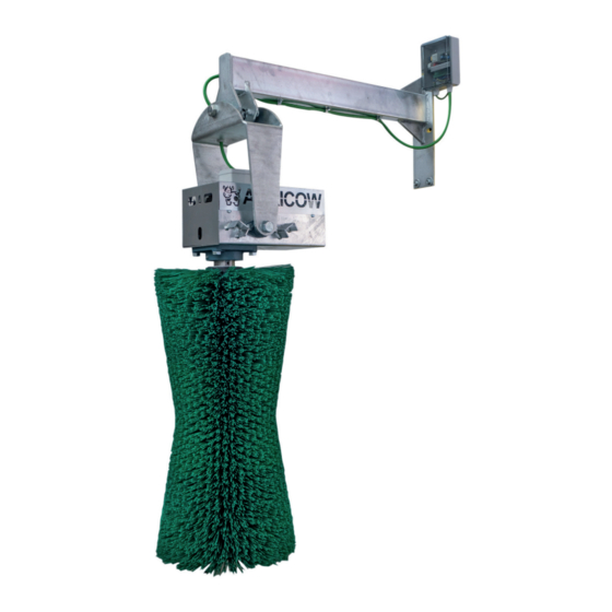
Page 2: Machine Description
Cattle Brushing Machine (BRUSH) Pendulum Description: The AGRICOW BRUSHING MACHINE has been designed to facilitate a more hygienic and efficient clea- ning of cattle, while rationalising costs with respect to traditional manual cleaning. AGRICOW owns Italian patent No. BS2005A000032, relating to “Apparatus for brushing cattle” and the equivalent European patent No. -
Page 3: Using The Machine
The machine is checked on Agricow premises before delivery as foreseen by internal procedures. Use: The cattle brush has been designed and produced for use as a system for cleaning the coat of dairy cows. One brush should be used for every 50/60 cows. -
Page 4: Ce Declaration Of Conformity
CE DECLARATION OF CONFORMITY (In compliance with the EC Machinery Directive 2006/42/EC e s.m.i., Annex II/A) The company AGRICOW Srl - Via Caduti del Lavoro, 88 - 25013 Carpenedolo - (Brescia) Italy Declares, on its own responsibility , that the machine... -
Page 5: Safety Instructions
Inversion of rotation when meeting resistance in the presence of an obstacle • • If the maximum force is exceeded, the brush inverts direction and rotates in the opposite direction for 1 minute, after which it returns to rest position. -
Page 6: Warranty
The checks and verification of the anomaly will be carried out by the specialist personnel in charge. Mechanical parts of the brush, such as motors and gearboxes out of warranty must be disposed of locally and should in no way be returned to Agricow. -
Page 7: Periodic Maintenance
Photo of the motor and/or gearbox label; photo of the electronic card bearing the sensor error number. It is also understood that AGRICOW is not liable for any direct or indirect damages caused to persons or things by defects and breakdowns of the machine or resulting from forced suspension in its use. -
Page 8: Installation And Assembly
Optimal positioning and stable fastening are particularly important for the correct operation of the Agricow pendulum brush. It is thus important to ensure that the mounting surface is stable and not exposed to vibrations or movement. - Page 9 Use and Maintenance Instructions Fig. 1 Fig. 2 Fig. 3 Fig. 4 cable free 45 cm / 17.72” Fig. 5...
- Page 10 Book Plate PARTICOLARE PIASTRA 12.0 cm 1.1 cm 3.0 cm 29,52” / 35.43” 3.8 cm Recommended installation height ATTENTION: The height of the brush must accommodate the different shoulder’s height of the animal (75/90 cm or 29,52”/35.43”). SEE PIC .
-
Page 11: Description Of Control Panel And Display
DL1 RED LED REVERSE MOTOR ROTATION OVERVOLTAGE ALARM UNDERVOLTAGE ALARM BOARD OVERHEATING ALARM DISCONNECTED MOTOR ALARM MOTOR BLOCK ALARM POWER FUSE 10A (12,5A SL49A) Pendulum BRUSH SELECTION MOTOR START DL2 GREEN LED 3-WIRE INCLINATION SENSOR NEUTRAL (Blue) GREY SISTEMA ELETTRONICO BROWN... - Page 12 The SL49 board manages the operation of electric brushes for farmed cattle, controlling the start motor contact, the operation time, the direction of rotation and the force applied to the brush itself. It supports monophase 230VAC motors (1HP max) for the standard version and 115VAC (0.5HP max) for version “A”.
- Page 13 90 seconds. The end of each cycle is followed by a pause of about 4 seconds; when the device is activated again, the motor starts to turn in the opposite direction to that of the previous cycle in order to use the brush evenly. The display shows the letters “R” and “L” to indicate the sense of rotation.
- Page 14 Description of LED meaning Rif. Colour Description Presence of voltage supply. GREEN On: inclination sensor at rest (brush stopped after time out). Off: inclination sensor active (brush in operation). Description of display messages Carattere Description Flashing, board active, awaiting work cycle...
-
Page 15: Fault Tree
• Fuse F1 burnt out. Remove voltage from brush and replace the 10A fuse F1, pressing the cap and turning slightly anti-clockwise. Supply voltage to brush and check that the red LED DL1 lights up. If the fuse burns immediately, the board is faulty. - Page 16 Replace board. • Motor with locked mechanical parts. Replace motor. 6. The brush attempts to start five consecutive times but does not turn, then it stops for 4 minutes; the display shows the alarm message “5”: • Motor is mechanically blocked.
Need help?
Do you have a question about the BRUSH and is the answer not in the manual?
Questions and answers