
Summary of Contents for Covidien Valleylab FT Series
- Page 1 User’s Guide Valleylab FT10 FT Series Energy Platform For use with software version 1.1x Part Number: PT00016328...
-
Page 2: Preface
This guide and the equipment it describes are for use only by qualified medical professionals trained in the particular technique and surgical procedure to be performed. It is intended as a guide for using the Covidien Valleylab FT10 FT Series Energy Platform only. Additional technical information, such as circuit diagrams, component part lists,... -
Page 3: Limited Warranty
This limited warranty does not apply to any product, or part thereof, which has been repaired or altered in a way so as, in Covidien’s judgment, to affect its stability or reliability, or which has been subjected to misuse, neglect, or accident. -
Page 4: Software License
Customer’s intent to exercise any such rights unless an order of a government agency of competent jurisdiction will not so allow. This License will terminate immediately upon notice from Covidien if Customer fails to comply with any provision of this License or any agreement. - Page 5 Customer. 5. Change Orders: Covidien shall have the right, at any time during the Term, by written request to Customer (an “Update Notice”), to require that Customer return the Products and Software to Covidien for such periods of time as are required by Covidien (“Update...
- Page 6 Covidien, in its sole discretion, from time to time. Covidien shall have no warranty obligations with respect to any failures of the Software that are the result of accident, abuse, misapplication, extreme power surge or extreme electromagnetic field, or any other cause outside of Covidien’s control.
- Page 7 Software License 10. Survival. Sections 2, 3, 4, 8, 9 and this Section 10 shall survive the termination or expiration of these Software License Terms. Valleylab FT10 Energy Platform User’s Guide...
-
Page 9: Table Of Contents
Contents Preface ..........ii Limited Warranty . - Page 10 Chapter 3. System Setup Setup ..........3-2 Unpacking the System.
- Page 11 Chapter 5. Bipolar Front Panel Bipolar Features ......5-2 Rear Panel Bipolar Features......5-3 Bipolar Quick Setup Instructions .
- Page 12 Service Manual Copies and Updates ..... . 9-6 Covidien Technical Service......9-6 Training/Education.
- Page 13 Wireless Fidelity (WiFi) ......10-7 Ethernet ........10-8 Symbols Used .
-
Page 15: Chapter 1. Overview And General Features
Chapter 1 Overview and General Features This chapter provides an overview of the features and functions of the Valleylab FT10 FT Series Energy Platform. Precaution Read the instructions, warnings, and precautions provided with this energy platform and associated accessories before using. Specific instructions for electrosurgical instruments are not included in this manual. -
Page 16: The Valleylab Ft10 Energy Platform
The VLFT10GEN, applied parts (patient return electrodes and active instruments) are designed to work as a system. Covidien offers a selection of patient return electrodes and active instruments that are fully compatible with this energy platform. -
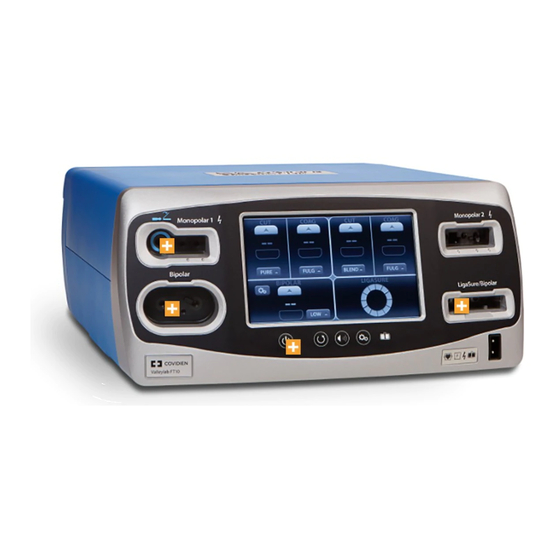
Page 17: Front Panel
The Valleylab FT10 Energy Platform Front Panel FT10 On/Off button Restore Settings button Audio Volume control button Service/Settings button REM (Return Electrode Monitoring) indicator Interface touchscreen REM patient return electrode receptacle LigaSure™/Bipolar receptacle Monopolar 2 instrument receptacle Monopolar 1 Universal Foot Pedal Port (UFP) receptacle Bipolar instrument receptacle Valleylab FT10 Energy Platform User’s Guide... -
Page 18: Rear Panel
The Valleylab FT10 Energy Platform Rear Panel Monopolar 2 Monopolar 1 Bipolar Warning: Risk of Fire. Replace Fuse as Marked 250V, F10.0A (100-127Vac) 250V, F6.3A (220-240Vac) M onopolar M onopolar Avertissement: Risque du feu. Remplacez les fusibles comme marqués. 250V, F10.0A (100-127Vac) 250V, F6.3A (220-240Vac) Monopolar 2 foot-pedal receptacle (requires included adapter to connect standard four-pin monopolar foot pedal) -
Page 19: Modes & Settings
The Valleylab FT10 Energy Platform Modes & Settings The VLFT10GEN provides the following modes and settings for a variety of surgical procedures: Monopolar modes Power-Setting Ranges Peak Voltage - PURE Off, 1–300 W 1287 V - BLEND Off, 1–200 W 2178 V ... - Page 20 SPRAY delivers wider fulguration; penetration is shallower and the affected tissue area is larger than with the FULGURATE mode. Compatible Monopolar Instruments & Devices The following Covidien catalog numbers for monopolar surgical instruments, return electrodes, foot pedals, and adapters are fully compatible with the VLFT10GEN. UFP-Receptacle Adapter (connect only to Monopolar 1)
- Page 21 The Valleylab FT10 Energy Platform Instruments (connect to either Monopolar 1 or Monopolar 2) This generator is designed for use with Covidien monopolar instruments. However, monopolar instruments are compatible with the VLFT10GEN if they have a connector that matches the following figure and are rated for peak voltages of at least 3933 V.
- Page 22 The Valleylab FT10 Energy Platform Foot Pedals FT6003 ForceTriad Three-Pedal Footswitch (Monopolar 2 only) E6008 Valleylab Monopolar Footswitch (Monopolar 1, Monopolar 2 with adapter) E6008B Valleylab Monopolar Footswitch (Monopolar 1, Monopolar 2 with adapter) 1017577 6-Pin to 4-Pin Monopolar Footswitch Adapter (Monopolar 2 only) Bipolar Effects Selection of Bipolar effects and power settings is dependent on surgeon preferences, tissue characteristics, accessories selection, and the intended clinical application.
- Page 23 Do not use the FT0501 ForceTriad Bipolar Adapter with Auto Bipolar on the VLFT10GEN. Compatible Bipolar Instruments & Devices The VLFT10GEN is designed for use with Covidien bipolar instruments. However, other bipolar instruments are compatible with the FT10 if their connectors match the following illustration and are rated for peak voltages of at least 531 V.
- Page 24 The Valleylab FT10 Energy Platform The following Covidien catalog numbers for bipolar foot pedals are fully compatible with the VLFT10GEN. Foot Pedals E6009 Valleylab Bipolar Standard Footswitch E6009B Valleylab Bipolar Standard Footswitch E6019 Valleylab Bipolar Dome Footswitch Bipolar Resection Bipolar Resection configures the LigaSure/Bipolar receptacle to use bipolar-resection resectoscopes.
- Page 25 Compatible LigaSure Instruments & Devices This generator is designed for use with Covidien LigaSure instruments that have a connector that matches the following figures and are rated for peak voltages of at least 244 V. However, it does not recognize all LigaSure instruments. Please refer to the cover of the instructions for use to confirm if a specific LigaSure catalog number is compatible with the VLFT10GEN.
- Page 26 The Valleylab FT10 Energy Platform LigaSure with Switching A. Utilizes 4 mm banana pins B. Utilizes 2 mm banana pins The following LigaSure foot pedal is fully compatible with the VLFT10GEN. Foot Pedal LS0300 Tissue Fusion Footswitch, Purple Connection to External Systems The VLFT10GEN can be connected to an external system.
-
Page 27: System Conventions
System Conventions System Conventions The Touchscreen The VLFT10GEN features a user-friendly touchscreen interface to control system functions. The touchscreen is divided into quadrants; each of the four sections is associated with an adjacent instrument receptacle. • Quadrant 1—Settings entered in the touchscreen control an instrument attached to the Monopolar 1 receptacle. - Page 28 System Conventions Generator States The appearance of touchscreen components indicates one of the three states of the system. Edit When the system is powered on and no instrument is attached, the instrument controls in the monopolar and bipolar sections can be preset. The following illustration shows monopolar controls edited prior to inserting an instrument.
-
Page 29: System Buttons
System Conventions Activation The black background illuminates brightly when the instrument is activated. The following illustration shows the two-button pencil is currently delivering energy for PURE CUT. The mode controls are locked during activation preventing any change in the mode. Power settings can be changed during activation. -
Page 30: Interface Conventions
System Conventions Interface Conventions Interface Element Name Description Pop-up window/ Pop-up windows and menus appear on screen menu when user input is needed or requested. Pop- ups close if the user touches anywhere outside of the pop-up window. Up/Down arrows Up and down arrows indicate additional values or selections are available for the current setting. -
Page 31: Chapter 2. Warnings And Precautions For Patient And Operating Room Safety
Chapter 2 Warnings and Precautions for Patient and Operating Room Safety The safe and effective use of electrosurgery depends to a large degree upon factors solely under the control of the operator. There is no substitute for a properly trained and vigilant surgical team. It is important that the operating instructions supplied with this or any electrosurgical equipment be read, understood, and followed. -
Page 32: General Warnings And Precautions
General Warnings and Precautions General Warnings and Precautions Fire/Explosion Hazards Warning Danger - Explosion Hazard Do not use electrosurgery in the presence of flammable anesthetics or oxidizing gases (such as nitrous oxide (N O and oxygen) or in close proximity of to volatile solvents (such as ether or alcohol). -
Page 33: System Setup Warnings And Precautions
General Warnings and Precautions System Setup Warnings and Precautions Warning Electric Shock Hazard Connect the system power cord to a properly grounded power receptacle. Do not use power plug adapters. Electric Shock Hazard When taking measurements or troubleshooting the system, take appropriate precautions, such as using isolated tools and equipment, using the “one hand rule,”... - Page 34 For surgical procedures where the current could flow through delicate parts of the body, the use of bipolar techniques may be desirable in order to avoid unwanted coagulation. Connect only Covidien-approved devices. Using devices from other manufacturers may cause equipment malfunction or patient injury.
- Page 35 General Warnings and Precautions Precaution Inadvertent activation may occur while installing, removing, or bending electrodes. Ensure that the instrument cord is not connected to the VLFT10GEN or that the system is off. Leads connected to the patient should be positioned in such a way that contact with the patient or other leads is avoided because the capacitance between the electrode cable and the patient may result in some local high current densities.
-
Page 36: Warnings And Precautions For The Energy Platform
General Warnings and Precautions Important If required by local codes, connect the energy platform to the hospital potential equalization system with an equipotential cable. The operator of the generator may be as far away from the generator as 2 feet (direct product interaction), 5 feet (inside the sterile field), and 13 feet (across the room working with other equipment). -
Page 37: Warnings And Precautions For Active Instruments
General Warnings and Precautions Notice Make no modifications to the energy platform. Any modifications to the system will void the warranty. When testing RF equipment, follow these test procedures. Keep test leads to the minimum length usable; lead inductance and stray capacitance can adversely affect readings. Carefully select suitable ground points to avoid ground loop error in measurements. -
Page 38: Warnings For Implanted Electronic Devices (Ieds)
Notice All Covidien instruments have voltage ratings that are greater than the maximum output voltages in the VLFT10GEN and are thus fully compatible. Inspect instrument plugs for wear before every use. Worn plugs may result in a loose or stuck connection to the generator. -
Page 39: Warnings And Precautions For Monopolar Procedures
Warnings and Precautions for Monopolar Procedures Warnings and Precautions for Monopolar Procedures Warning Simultaneously activating suction/irrigation and electrosurgical current may result in increased arcing at the electrode tip, burns to unintended tissues, or shocks and burns to the surgical team. Power output of a two- or three-button pencil (CUT and COAG selections) can change during use when another foot pedal is pressed. -
Page 40: Warnings And Precautions For Patient Return Electrodes
When using a Covidien energy platform or a patient return electrode during these types of surgical procedures, the user should seek written guidance in the form of detailed user instructions from the manufacturer of the active accessory regarding the currents and duty cycles that can be expected. -
Page 41: Inadvertent Radio Frequency (Rf) Burns
Important A statement of compatibility from the CQM patient return electrode manufacturer should be obtained prior to the use of a non-Covidien CQM patient return electrode. A patient return electrode is not necessary in bipolar or LigaSure procedures. Inadvertent Radio Frequency (RF) Burns... -
Page 42: Warnings And Cautions For Laparoscopic Procedures
Do not activate the LigaSure function in an open-circuit condition. Activate the energy platform only when the instrument is near or in direct contact with the target tissue to reduce the possibility of unintended burns. Covidien recommends against the use of laparoscopic surgery on pregnant patients. 2-12 Valleylab FT10 Energy Platform User’s Guide... -
Page 43: Warnings And Precautions For Bipolar Procedures
Warnings and Precautions for Bipolar Procedures Warning Use of different Covidien cord models or cords from other manufacturers may not achieve proper electrical output for this device, thereby failing to produce the desired clinical effect. For example, Auto Bipolar activation/deactivation settings may not work properly using cords other than those specified by Covidien. -
Page 44: Warnings And Precautions For Bipolar Resection
LigaSure/Bipolar receptacle with a Covidien Bipolar Resection cord. In addition, Bipolar Resection mode can be activated only with the Covidien Bipolar Resection foot pedal connected to the LigaSure/Bipolar foot-pedal receptacle. See the cords IFU listed in Accessories on page 1-10 for the list of supported Bipolar Resection instruments and cords. -
Page 45: Shunt Cords
Shunt Cords Notice Refer to this system’s service manual for maintenance recommendations, and function and output- power verification procedures. Do not spray cleaning fluids directly on the generator as damage to the generator may occur. The latest version of the Valleylab FT10 Energy Platform Service Manual is available at www.BioMedConnect.com. -
Page 47: Chapter 3. System Setup
Chapter 3 System Setup This chapter describes how to set up the energy platform, turn it on, and configure system settings. Precaution Read the instructions, warnings, and precautions provided with this energy platform and associated accessories before using. Specific instructions for electrosurgical instruments are not included in this manual. -
Page 48: Setup
Setup Setup Unpacking the System Carefully unpack the contents of the shipping container. The container contains the following items: • Valleylab FT10 FT Series Energy Platform • Power cord • First-time setup guide • Quick reference card • User’s guide •... -
Page 49: Turning On The Vlft10Gen
1. Turn on the system by depressing the On/Off button on the front panel. Observe the following during the power-on self-test (POST): • The Covidien logo appears on screen. • A status bar indicates authentication activity. • The system revision code appears. -
Page 50: System Functions
System Functions System Functions The VLFT10GEN system functions are accessed from buttons on the front panel: On/Off, Restore, Audio Volume, and Service and Settings. On/Off When the system is plugged into a power source, the On/Off button appears yellow. Turn on power to the energy platform by pressing and holding the On/Off button for 0.25 seconds. -
Page 51: Audio Volume
System Functions Audio Volume The VLFT10GEN has five levels of audio volume. Press the audio-volume button on the front panel to view the volume-select menu. The factory setting is as shown with the volume set at it’s highest level. Adjust the volume using the + or - buttons. -
Page 52: Service And Settings
The Service and Settings menu is accessed by pressing the gears button on the front panel. The Service and Settings menu displays the generator serial number, IP address (if connected to the network), software version number, and contact information for the Covidien Service Center. It provides available options for • Viewing logs –... -
Page 53: Logs
Service and Settings Logs The LOGS button displays the LOGS menu with three options. 1. Touch the LOGS button to view the Logs menu: • EVENTS—A detailed display of all user actions and generator events on the VLFT10GEN • ERROR—A display of all recorded system errors with details •... -
Page 54: Demo Mode
Service and Settings DEMO Mode DEMO mode is used for demonstration of the generator and accessories only. DEMO mode enables monopolar activation through an attached instrument without the use of a REM patient return electrode. When the monopolar surgery is performed clinically, the required return electrode provides a safe path for the current introduced to the patient’s body. -
Page 55: System Menu
Diagnostics • Instrument Bar Code Reader—Insert a Covidien device with a scannable bar code. When the SCAN button is touched, the bar-code reader displays the current view from the reader’s camera to verify it is working properly. - Page 56 Service and Settings Network The Network button allows the technician to select a network connection to the Valleylab Exchange server for service operations. There are 4 ways to connect to the IT network: • Wired Point-to-Point • Wired Automatic • Wired Manual •...
-
Page 57: Service Menu
Service and Settings Service Menu Items in the Covidien Service menu are specifically for qualified service personnel and are password protected. The password is 423213. The Service Menu button accesses settings • RF Output Test • Touchscreen Calibration • Energy Calibration •... -
Page 59: Chapter 4. Monopolar
Chapter 4 Monopolar This chapter describes the Monopolar function of the VLFT10GEN. Precaution Read the instructions, warnings, and precautions provided with this energy platform and associated accessories before using. Specific instructions for electrosurgical instruments are not included in this manual. Valleylab FT10 Energy Platform User’s Guide... -
Page 60: Front Panel Monopolar Features
Front Panel Monopolar Features Front Panel Monopolar Features FT10 Monopolar 1 Universal Foot Pedal Port (UFP) receptacle Monopolar 1 touchscreen quadrant Monopolar 2 touchscreen quadrant Monopolar 2 instrument receptacle REM Patient return electrode receptacle Return electrode monitoring (REM) indicator Valleylab FT10 Energy Platform User’s Guide... -
Page 61: Rear Panel Monopolar Features
Rear Panel Monopolar Features Rear Panel Monopolar Features Monopolar 2 Monopolar 1 Bipolar Warning: Risk of Fire. Replace Fuse as Marked 250V, F10.0A (100-127Vac) 250V, F6.3A (220-240Vac) M onopolar M onopolar Avertissement: Risque du feu. Remplacez les fusibles comme marqués. 250V, F10.0A (100-127Vac) 250V, F6.3A (220-240Vac) Monopolar 2 foot-pedal receptacle (requires adapter to connect standard four-pin... -
Page 62: Monopolar Quick Setup Instructions
The Monopolar 2 receptacle requires an adapter to connect a standard 4-pin monopolar foot pedal. Warning Use only Covidien foot pedals. Use of other manufacturer’s foot pedals is not recommended; unexpected output may occur. 5. Apply the patient return electrode to the patient and connect it to the patient return electrode receptacle on the generator’s front panel. -
Page 63: Monopolar Function Overview
1 or Monopolar 2 receptacles on the front panel. Standard foot-pedal devices attached to the Monopolar 1 Universal Foot Pedal Port receptacle on the front panel can be controlled with a Covidien foot pedal attached to the Monopolar 1 foot-pedal receptacle on the back panel. -
Page 64: Monopolar Foot-Pedal Activation
Precaution Connect only Covidien foot pedals. Using foot pedals from other manufacturers may cause equipment malfunction or patient injury. See the list of compatible Covidien foot pedals on page 1- Monopolar Foot-Pedal Activation All devices attached to the Monopolar 1 or Monopolar 2 receptacle—whether handswitching or foot-pedal-activated accessories—can be controlled with a foot pedal. -
Page 65: Return Electrodes - Rem Contact Quality Monitoring System
When using a Covidien energy platform or a patient return electrode during these types of surgical procedures, the user should seek written guidance in the form of detailed user instructions from the manufacturer of the active accessory regarding the currents and duty cycles that can be expected. -
Page 66: Patient Return Electrode Setup
Return Electrodes – REM Contact Quality Monitoring System A REM alarm sounds and the system stops producing output power when either of the following occurs: • The measured resistance is below 5 Ω or above 135 Ω, the limits of the standard range of safe resistance. - Page 67 Return Electrodes – REM Contact Quality Monitoring System Warning Do not cut a patient return electrode to reduce its size. Patient burns due to high-current density may result. 1. Select a well vascularized, convex area in close proximity to the surgical site for electrode application.
-
Page 68: Monopolar Electrodes
Monopolar Electrodes Connect a monopolar instrument to the Monopolar 1 or Monopolar 2 instrument receptacle on the front of the energy platform. See the Covidien instrument’s instructions for use for recommendations on which receptacle to use. The Monopolar 1 UFP receptacle, identified by a blue ring, accepts connectors of various sizes when coupled with the E05021 and E050212 UFP adapters. -
Page 69: Standard Monopolar Mode Functionality
Automatic Settings for a Recognized Instrument Some Covidien instruments compatible with the FT10 have an identification that is recognized by the system when attached to the Monopolar 2 receptacle. The energy platform automatically sets the default mode and power level assigned to the instrument. -
Page 70: Valleylab Mode Functionality
Inserting an instrument highlights the corresponding quadrant. VALLEYLAB Mode Functionality Covidien instruments featuring the VALLEYLAB mode—a unique combination of hemostasis and dissection—are specialty devices providing output control from the sterile field. Some have a sliding power control on the instrument that enables direct adjustments to power output during surgery. - Page 71 Monopolar Electrodes When an instrument with VALLEYLAB-mode capability is attached to the Monopolar 2 receptacle, the energy platform detects the instrument type and changes the screen from the default two-button to the corresponding screen. Force TriVerse Screen Power bar indicator Slider position indicator CUT mode ON/OFF switch CUT mode power indicator (watts)
-
Page 72: Using A Valleylab-Mode Instrument
Monopolar Electrodes Using a VALLEYLAB-Mode Instrument 1. Select the desired power level by touching the up and down arrows on the power- output mode. A brief double tone sounds. Power output is displayed in watts. The power level cannot be changed during instrument activation. Warning The power-selecting slider, if available on the instrument, increases and decreases power output. -
Page 73: After Surgery
After Surgery After Surgery Disconnect the instruments 1. Turn off the energy platform. 2. Disconnect all instruments from the front panel. 3. Dispose of the instrument according to the procedures for your institution. 4. Disconnect and store any foot pedals used. 5. -
Page 75: Chapter 5. Bipolar
Chapter 5 Bipolar This chapter describes the Bipolar function of the VLFT10GEN. Precaution Read the instructions, warnings, and precautions provided with this energy platform and associated accessories before using. Specific instructions for electrosurgical instruments are not included in this manual. Valleylab FT10 Energy Platform User’s Guide... -
Page 76: Front Panel Bipolar Features
Front Panel Bipolar Features Front Panel Bipolar Features FT10 Bipolar receptacle Bipolar touchscreen quadrant Bipolar settings button Valleylab FT10 Energy Platform User’s Guide... -
Page 77: Rear Panel Bipolar Features
4. If using a foot pedal, connect it to the Bipolar foot-pedal receptacle on the rear panel. Warning Use only Covidien foot pedals. Use of other manufacturer’s foot pedals is not recommended; unexpected output may occur. 5. Connect the instrument to the Bipolar instrument receptacle on the front panel. -
Page 78: Bipolar Function Overview
Bipolar Function Overview Bipolar Function Overview Delicate tissue requires less energy to desiccate. The VLFT10GEN provides low-voltage, continuous current for faster dessication without sparking. The possibility of sparking increases as desiccated tissue becomes more resistant to energy flow. The system protects against sparking by limiting the bipolar voltage at relatively high levels of tissue impedance. -
Page 79: Foot Pedal
If pedal activation is to be used with a bipolar instrument, attach the bipolar foot-pedal connector to the Bipolar foot-pedal receptacle on the rear panel. Warning Use only Covidien foot pedals. Use of other manufacturer’s foot pedals is not recommended; unexpected output may occur. Virtual Ammeter The virtual ammeter on the bipolar quadrant displays the current delivered during bipolar- instrument activation. -
Page 80: Auto Bipolar Function
Auto Bipolar Function 2. Touch the ammeter ON/OFF switch to enable the visual ammeter and audio ammeter tones for Bipolar procedures. 3. Touch OK to close the ammeter settings window and retain any changes. The visual ammeter is added to the Bipolar screen and the audio and visual feedback is in use during Bipolar activation. -
Page 81: Enable/Disable Auto Bipolar
Auto Bipolar Function Enable/Disable Auto Bipolar 1. Access Bipolar settings by touching the settings button in the Bipolar quadrant. The Bipolar settings appear with the default Auto Bipolar setting OFF 2. Touch the AUTO ON/OFF switch. 3. A confirmation screen appears over the Bipolar quadrant. Touch Yes to enable, or No to reject. -
Page 82: Setting The Auto Bipolar Activation Delay
Auto Bipolar Function Warning Use of different Covidien cord models or cords from other manufacturers may not achieve proper electrical output for this device, thereby failing to produce the desired clinical effect. For example, Auto Bipolar activation/deactivation settings may not work properly using cords other than those specified by Covidien. -
Page 83: Shutting Down Bipolar Functions
Shutting Down Bipolar Functions Shutting Down Bipolar Functions The Auto Bipolar settings can be exited quickly to change non-setting controls in response to the surgeon’s needs. Any of the following actions closes the window and reopens it with the last saved settings. •... -
Page 85: Chapter 6. Ligasure
Chapter 6 LigaSure This chapter describes how to set up and operate the LigaSure tissue-fusion function of the VLFT10GEN. Precaution Read the instructions, warnings, and precautions provided with this energy platform and associated accessories before using. Specific instructions for electrosurgical instruments are not included in this manual. -
Page 86: Front Panel Ligasure Features
Front Panel LigaSure Features Front Panel LigaSure Features FT10 LigaSure quadrant LigaSure/Bipolar receptacle Monopolar 2 quadrant (for LigaSure dual-plug instruments) Monopolar 2 receptacle (for LigaSure dual-plug instruments) Rear Panel LigaSure Features Monopolar 2 Monopolar 1 Bipolar Warning: Risk of Fire. Replace Fuse as Marked 250V, F10.0A (100-127Vac) 250V, F6.3A (220-240Vac) -
Page 87: Ligasure Quick Setup Instructions
LigaSure Quick Setup Instructions LigaSure Quick Setup Instructions If you are familiar with the VLFT10GEN, follow this abbreviated procedure to setup the system for LigaSure tissue fusion. The following instructions are for a single-plug instrument, which covers most LigaSure devices. For devices that have two plugs and provide both LigaSure and monopolar functionality, see Connecting Dual-Plug LigaSure Instruments on page 6-8. -
Page 88: Ligasure Function Overview
LigaSure Function Overview LigaSure Function Overview LigaSure tissue fusion can be used on arteries, veins, and lymphatics, up to and including, 7 mm in diameter and tissue bundles. This system provides precise energy delivery and electrode pressure to tissues for a controlled time period to achieve a complete and permanent fusion of tissues and vessel lumens. -
Page 89: Ligasure Default Settings
LigaSure Function Overview LigaSure Default Settings Output or Instrument Default LigaSure Handswitching—enabled (On) LF5544 Pistol Grip • MONOPOLAR mode—VALLEYLAB – 15 W LF5637 and LF5644 • MONOPOLAR mode—VALLEYLAB • Monopolar power – CUT—15 W – VALLEYLAB—15 W – COAG—15 W LigaSure/Bipolar Receptacle The LigaSure/Bipolar receptacle is located adjacent to the lower-right quadrant of the screen. -
Page 90: Foot Pedal
LigaSure Instruments Foot Pedal A single-pedal LigaSure foot pedal can be used when the energy platform is using the LigaSure quadrant. LigaSure Instruments Reusable-Instrument Assembly To prepare the reusable LigaSure instruments for use in a procedure, refer to the following steps for the general preparation. - Page 91 LigaSure Instruments If applicable, refer to the following sections: • Hand-Activation ON/OFF Switch on page 6-9 • Invalid Instrument on page 6-9 Connecting Single-Plug LigaSure Instruments There are multiple instrument designs, but the general LigaSure-instrument connection process is the same for LigaSure instruments with a single purple LigaSure connector. For devices that have two plugs and provide both LigaSure and monopolar functionality, see Connecting Dual-Plug LigaSure Instruments on page 6-8.
- Page 92 LigaSure Instruments Connecting Dual-Plug LigaSure Instruments LigaSure connector (purple) LigaSure/Bipolar instrument receptacle Monopolar connector (blue) Monopolar 2 instrument receptacle LigaSure touchscreen quadrant Monopolar 2 touchscreen quadrant REM patient return electrode Setup 1. With the bar code on the purple LigaSure connector (1) facing up, firmly insert it into the LigaSure/Bipolar receptacle (2) next to the LigaSure touchscreen quadrant (5).
- Page 93 LigaSure Instruments Hand-Activation ON/OFF Switch Some LigaSure instruments cause the hand-activation icon to appear in the lower left corner of the LigaSure control panel. The hand-activation switch toggles between the ON and OFF setting. For example, the LF1212 Curved, Small Jaw, Open Sealer/Divider, is a LigaSure instrument that can be used with hand-activation on or off.
-
Page 94: Activating The Ligasure Instrument
Activating the LigaSure Instrument Activating the LigaSure Instrument 1. Fully grasp the target tissue in accordance with the LigaSure instrument’s IFU. 2. Activate the LigaSure instrument either by pressing and holding the activation button on the instrument or by depressing the foot pedal. During instrument activation, the LigaSure quadrant of the display illuminates purple and rotates clockwise, and an activation tone sounds for the duration of energy delivery. - Page 95 Activating the LigaSure Instrument Incomplete Seal Cycle - Short The generator detected a short circuit between the LigaSure jaws—possibly due to contact with a metal object or excess fluid around the surgical site. If this message appears the user should 1.
-
Page 96: After Surgery
After Surgery Incomplete Seal Cycle - Time Out Additional time and energy are needed to complete the seal cycle. If this message appears, the user should 1. Release the foot pedal or activation button. 2. Open the instrument jaws and inspect for a successful seal. 3. -
Page 97: Chapter 7. Bipolar Resection
Chapter 7 Bipolar Resection This chapter describes how to set up and operate the Bipolar Resection application on the energy platform. For information about setting up and using the Bipolar Resection application, refer to these documents: • This chapter. • ForceTriad Bipolar Resection Footswitch Instructions for Use (FT6009) - Instructions for the only foot pedal that supports Bipolar Resection mode. -
Page 98: Front Panel Bipolar Resection Features
Front Panel Bipolar Resection Features Front Panel Bipolar Resection Features FT10 LigaSure/Bipolar receptacle Bipolar Resection quadrant (appears upon insertion of Bipolar Resection instrument) Rear Panel Bipolar Resection Features Monopolar 2 Monopolar 1 Bipolar Warning: Risk of Fire. Replace Fuse as Marked 250V, F10.0A (100-127Vac) 250V, F6.3A (220-240Vac) M onopolar... -
Page 99: Bipolar Resection Function Overview
Bipolar Resection Function Overview Bipolar Resection Function Overview Certain urology and gynecology procedures use resection electrodes in a saline environment requiring high bipolar-power outputs to obtain resection and hemostasis performance. Bipolar Resection function provides two different effect modes: • CUT effect for resection, activated by the yellow (left) foot pedal •... -
Page 100: Bipolar Resection Default Settings
Bipolar Resection Function Overview Bipolar Resection Default Settings Output or Instrument Default Bipolar Resection • CUT effect—1 • COAG effect—1 Warning Electric Shock Hazard • Do not connect wet instruments to the energy platform. • Ensure that all instruments are correctly connected and that no metal is exposed at any connection point. -
Page 101: Foot Pedal
Bipolar Resection Function Overview Foot Pedal The LigaSure/Bipolar foot-pedal receptacle is located on the rear panel of the energy platform. Monopolar 2 Monopolar 1 Bipolar LigaSure/Bipolar foot-pedal receptacle When Bipolar Resection is in use, a single dual-pedal Bipolar Resection Footswitch can be attached to the LigaSure/Bipolar foot-pedal receptacle using a 1060355 adapter. -
Page 102: Connecting Bipolar Resection Instruments To The Energy
Bipolar Resection Function Overview Connecting Bipolar Resection Instruments to the Energy Platform Warning Malfunction may be caused by a loose or incorrect connection of the cord to the energy platform or instrument. Worn cords cannot be repaired. Replace cords on a routine basis to maintain optimum functionality and reliability in operating-room use. -
Page 103: Bipolar Resection Settings
Bipolar Resection Settings Bipolar Resection Settings Changing the Energy-Delivery Setting Warning Confirm proper power or intensity settings before proceeding with surgery. Touch either the up or down arrows to increase or decrease the effect setting by one. The effect setting does not advance from 6 to 1 when touching the up arrow or from 1 to 6 when touching the down arrow. -
Page 104: After Surgery
After Surgery After Surgery Disconnect the Instruments 1. Turn off the energy platform. 2. Disconnect the Bipolar Resection cord from the LigaSure/Bipolar receptacle from the front panel. 3. Disconnect the instrument from the cord. • If the instrument is single-use only (disposable), dispose of it according to the procedures for your institution. -
Page 105: Chapter 8. Troubleshooting
Chapter 8 Troubleshooting Precaution Read the instructions, warnings, and precautions provided with this energy platform and associated accessories before using. Specific instructions for electrosurgical instruments are not included in this manual. Valleylab FT10 Energy Platform User’s Guide... -
Page 106: General Troubleshooting Guidelines
When you correct a REM-alarm condition, the system is enabled and the REM-alarm indicator on the front panel illuminates green. Precaution Covidien REM Polyhesive patient return electrodes are recommended for use with the VLFT10GEN. Return electrodes from other manufacturers may not provide proper impedance to work correctly with the energy platform. -
Page 107: Correcting Malfunctions
FULGURATE and the SPRAY modes. Abnormal 50–60 Hz leakage Contact your biomedical currents. engineering department or a Covidien technical service representative for assistance. Energy platform does not Disconnected power cord or Check power cord connections respond when turned on. - Page 108 System Alarms on page 8-9. Use a backup energy platform. Contact your biomedical engineering department or a Covidien technical service representative for assistance. Energy platform is on and Malfunctioning foot pedal or Turn off the energy platform. instrument is activated, but handswitching instrument.
- Page 109 Correcting Malfunctions Situation Possible Cause Solution System does not detect Firmly insert the monopolar monopolar instrument. connector into the appropriate receptacle on the energy platform front panel. Ensure the associated monopolar quadrant indicates that it has detected the instrument. System does not detect bipolar Firmly insert the bipolar instrument.
- Page 110 Contact your The energy platform may biomedical engineering respond to the resulting department or a Covidien voltage differences between technical service representative grounded objects. for assistance. Valleylab FT10 Energy Platform User’s Guide...
- Page 111 Correcting Malfunctions Situation Possible Cause Solution Interference with other Metal-to-metal sparking. Check all connections to the devices only when the energy platform, patient energy platform is activated. return electrode, and instruments. High settings used for Use lower power settings for FULGURATION.
- Page 112 Correcting Malfunctions Situation Possible Cause Solution Pacemaker interference. Intermittent connections or Check the active and patient metal-to-metal sparking. return electrode cord connections. It may be necessary to reprogram the pacemaker. Current traveling from active Consult the pacemaker to return electrode during manufacturer or hospital monopolar electrosurgery is cardiology department for...
-
Page 113: System Alarms
Correcting Malfunctions System Alarms Most system alarms require some action on the user’s part to correct the condition; however, some are corrected automatically. Use the following list to determine how to correct an alarm condition. After correcting the alarm condition, verify that the system completes the self-test as described in Chapter 3, System Setup. - Page 114 Correcting Malfunctions Error Error Title Description Alarm Type Clearing Condition Code E208 SYSTEM ERROR Stack Overflow High Alarm Power on reboot, successful POST E209 SYSTEM ERROR DMA Failure High Alarm Power on reboot, successful POST E210 SYSTEM ERROR Thread Limit High Alarm Power on reboot, Error...
- Page 115 Correcting Malfunctions Error Error Title Description Alarm Type Clearing Condition Code E225 SYSTEM ERROR Processor High Alarm Power on reboot, Watchdog Error successful POST E226 SYSTEM ERROR FPCA Comm High Alarm Power on reboot, Error successful POST E227 SYSTEM ERROR REM Circuit High Alarm Power on reboot,...
- Page 116 Correcting Malfunctions Error Error Title Description Alarm Type Clearing Condition Code E242 SYSTEM ERROR RF Data Timing High Alarm Power on reboot, Error successful POST E243 SYSTEM ERROR RF Data Delay High Alarm Power on reboot, Error successful POST E244 SYSTEM ERROR RF Interrupt Power on reboot,...
- Page 117 Correcting Malfunctions Error Error Title Description Alarm Type Clearing Condition Code E310 TOUCHSCREEN Unintentional Medium Alarm Condition clears ERROR Screen Input E312 INTERNAL CHECK Absolute Medium Alarm Reactivation, User Integrated Error acknowledge, Enter Service E313 INTERNAL CHECK Voltage Sensor Medium Alarm Reactivation, User Compare Error acknowledge, Enter...
- Page 118 Correcting Malfunctions Error Error Title Description Alarm Type Clearing Condition Code E326 CHECK Medium Alarm Switch release, INSTRUMENT Remove instrument E327 CHECK FOOT Medium Alarm Pedal release PEDAL E328 UNINTENTIONAL Panel Button Medium Alarm Button release INPUT Error E329 CHECK FOOT Invalid Foot Medium Alarm Condition clears...
- Page 119 Correcting Malfunctions Error Error Title Description Alarm Type Clearing Condition Code E342 INTERNAL CHECK Foot Pedal Medium Alarm Condition clears, User Comm Issue acknowledge, Enter Service E343 INTERNAL CHECK REM Comm Medium Alarm Condition clears, User Issue acknowledge, Enter Service E344 INTERNAL CHECK REM Comm...
- Page 120 Correcting Malfunctions Error Error Title Description Alarm Type Clearing Condition Code E401 AUTHORIZATION Invalid Pairing Low Alarm User acknowledge, ISSUE Code Enter Service E402 INCOMPLETE SEAL LigaSure Alarm Reactivation, Remove CYCLE instrument, User acknowledge, Enter Service, Install instrument E403 INCOMPLETE SEAL LigaSure Alarm Reactivation, Remove CYCLE...
- Page 121 Correcting Malfunctions Error Error Title Description Alarm Type Clearing Condition Code E415 FEATURE NOT Medium Alarm Remove instrument, ENABLED Enter Service, Dismiss message (select Okay or Cancel) E416 UNKNOWN Medium Alarm Remove instrument INSTRUMENT E417 INVALID Medium Alarm Remove instrument INSTRUMENT E419 Incomplete Setup...
-
Page 123: Chapter 9. Maintenance And Repair
• Product service • Service manual copies and updates • Returning the energy platform for service • Software updates • Covidien Technical Service • Training and education Precaution Read the instructions, warnings, and precautions provided with this energy platform and associated accessories before using. -
Page 124: Responsibility Of The Manufacturer
Responsibility of the Manufacturer Responsibility of the Manufacturer Covidien is responsible for the safety, reliability, and performance of the energy platform only if all of the following conditions have been met: • Installation and setup procedures in this manual are followed. -
Page 125: Cleaning
Product Service Covidien recommends that all VLFT10GEN systems be returned to the manufacturer for all service requirements. If any service is required without returning the system to the manufacturer, Covidien recommends that only qualified personnel service the VLFT10GEN system. -
Page 126: Returning The Energy Platform For Service
Product Service Returning the Energy Platform for Service Before returning the energy platform, call a Covidien sales representative for assistance. If the energy platform is to be sent to Covidien, do the following: 1. Obtain a return authorization number. Call the Covidien Technical Service Center (see page 9-6) to obtain a Return Authorization Number. -
Page 127: Software Updates
Software Updates Software Updates Software updates are available directly from Covidien by using the Valleylab Exchange Remote Software System application. Go to www.covidien.com/valleylabexchange to download and install the latest version of the Valleylab Exchange application. For additional information, the Valleylab Exchange Remote Software System User’s Guide is available on the Valleylab Exchange website. -
Page 128: Service Manual Copies And Updates
To request a hard copy of the service manual, call the telephone numbers listed in the next section. Covidien Technical Service For service, contact Covidien Technical Service or your VLFT10GEN sales representative. Contact a Covidien technical-service representative by telephone, email, or through the Internet: •... -
Page 129: Training/Education
Training/Education Training/Education For clinical professionals and service training options, please refer to the Covidien web site: http://www.covidien.com/education Valleylab FT10 Energy Platform User’s Guide... -
Page 131: Chapter 10. Technical Specifications
Chapter 10 Technical Specifications Precaution Read the instructions, warnings, and precautions provided with this energy platform and associated accessories before using. Specific instructions for electrosurgical instruments are not included in this manual. Valleylab FT10 Energy Platform User’s Guide 10-1... -
Page 132: Vlft10Gen Specifications
VLFT10GEN Specifications VLFT10GEN Specifications General Output configuration Isolated output Cooling Natural convection and fan Display 7 in. LCD touchscreen Connector receptacles LED illuminated connector readers on the LigaSure/Bipolar receptacle Enclosure Magnesium Mounting • Valleylab Universal Generator Cart (VLFTCRT) • Operating-room boom systems •... -
Page 133: Environmental Parameters
VLFT10GEN Specifications Environmental Parameters Operation Transport and Storage Ambient 50 to 104 °F (10 to 40 °C) 14 to 140 °F (-10 to +60 °C) temperature range Relative humidity 30% to 75% non-condensing 25% to 85% non-condensing Atmospheric 700 to 1060 millibars 500 to 1060 millibars pressure 1. -
Page 134: Power Cord Specifications
Plug - minimum 6 A - 250 VAC Unit receptacle - IEC female, minimum 6 A - 250 VAC Important Contact your local Covidien representative for alternative internationally approved power-cord options. Backup Power The VLFT10GEN retains all user programmed features, calibration, and statistical data when switched off and unplugged. -
Page 135: Internal Memory
VLFT10GEN Specifications Internal Memory Storage capacity 8 GB Duty Cycle The VLFT10GEN is capable of operating a duty cycle of 25%, defined as 10 seconds active and 30 seconds inactive, in any mode for a period of four hours. Precaution Use of duty cycles greater than 25% (10 seconds active followed by 30 seconds inactive) will increase the risk that heat build-up under a return electrode may be high enough to injure the patient. -
Page 136: Radio Frequency Identification (Rfid)
VLFT10GEN Specifications Radio Frequency Identification (RFID) The RFID module is located above the LigaSure/Bipolar receptacle. The intended use of the RFID module is to identify the inserted LigaSure instrument and configure the generator with the data included in the RFID tag. 13.56MHz Transmit/Receive Frequency Range 68.17 dBu V/m @3 meter... -
Page 137: Wireless Fidelity (Wifi)
VLFT10GEN Specifications Wireless Fidelity (WiFi) The WiFi module is located on the back of the generator. The intended use of the WiFi module is to perform service operations on the generator. Transmit/Receive Frequency Range 2.4000 ~ 2.4835 GHz (Industrial Scientific Medical Band) Standards IEEE 802.11b, 802.11g, 802.11n RF Output Power... -
Page 138: Ethernet
20 cm from the user or nearby persons. EU Declaration of Conformity Hereby, Covidien llc, declares that this wireless LAN and RFID are in compliance with the essential requirements and other relevant provisions of Directive 1999/5/EC. WiFi Device Installation Guide The translated Quick Installation Guide (QIG) for the WiFi device (EW-7811Un) is available on the Edimax™* website in many languages. -
Page 139: Symbols Used
Symbols Used Symbols Used For prescription use only Consult instructions for use Follow instructions for use (blue) Caution: Consult accompanying documents The energy platform output is floating (isolated) with respect to ground. Defibrillation proof DANGER Explosion risk if used with flammable anesthetics To reduce the risk of electric shock, do not remove the cover. - Page 140 Symbols Used Classified with respect to electrical shock, fire, and mechanical hazards only in accordance with AAMI ES standard 60601-1; certified to CSA standard C22.2 60601-1:2008. 3164410 3164410 Conforms to ANSI/AAMI std. ES60601-1:2005 Conforms to ANSI/AAMI std. ES60601-1:2005 Conforms to IEC std. 60601-2-2 Ed. 5 2009 Conforms to IEC std.
-
Page 141: Standards And Iec Classifications
Standards and IEC Classifications Foot pedal Volume adjustment for activation tones Equipotential grounding point Equipment should not be disposed in trash Do not reuse (Single use only) Standards and IEC Classifications The VLFT10GEN meets all pertinent clauses of the IEC 60601-1 editions 2.0 and 3.1, IEC 60601-2-2 editions 4.0 and 5.0, IEC 60601-1-2 editions 2.1 and 3.0 and 4.0, and IEC 60601-1-8 edition 2.1. -
Page 142: Ip21 Liquid Ingress/Spillage (Iec 60601-1 And Iec 60601-2-2)
Standards and IEC Classifications IP21 Liquid Ingress/Spillage (IEC 60601-1 and IEC 60601-2-2) The VLFT10GEN is constructed so that liquid spillage in normal use does not wet electrical insulation or other components which when wetted are likely to adversely affect the safety of the equipment. - Page 143 Standards and IEC Classifications Notice The system intentionally applies RF energy for diagnosis or treatment during activation. Observe other electronic medical equipment in the vicinity during the system activation for any possible adverse electromagnetic effects. Ensure adequate separation of electronic medical equipment based on observed reactions.
- Page 144 Standards and IEC Classifications Guidance and manufacturer’s declaration - electromagnetic immunity The Valleylab FT10 FT Series Energy Platform is intended for use in the electromagnetic environment specified below. The customer or the user of the Valleylab FT10 FT Series Energy Platform should assure that it is used in such an environment.
- Page 145 Standards and IEC Classifications Guidance and manufacturer’s declaration - electromagnetic immunity a. 1 cycle is at 50 Hz or 20 ms NOTE: U is the a.c. mains voltage prior to the application of the test level. Guidance and manufacturer’s declaration - electromagnetic immunity The Valleylab FT10 FT Series Energy Platform is intended for use in the electromagnetic environment specified below.
- Page 146 Standards and IEC Classifications Guidance and manufacturer’s declaration - electromagnetic immunity NOTE 1 At 80 MHz and 800 MHz, the higher frequency range applies. NOTE 2 These guidelines may not apply in all situations. Electromagnetic propagation is affected by absorption and reflection from structures, objects, and people. a.
- Page 147 Standards and IEC Classifications Recommended separation distances between portable and mobile RF communication equipment and the Valleylab FT10 FT Series Energy Platform Frequency ranges and text condition on transmitter bands Bands (MHz) Test Frequencies Modulation Claimed Compliance (MHz) Level V/m 380 –...
-
Page 148: Cables Used For Emc Compliance Testing
Standards and IEC Classifications Cables Used for EMC Compliance Testing The following cables, lengths, and instruments were used to determine compliance levels. Model No. Description Shielded Length Location Classification Tests Included 207002060 A/C cable 15 ft. Rear Emissions/ (4.6 m) panel Immunity 1017178... -
Page 149: Return Electrode Monitor (Rem)
Standards and IEC Classifications Model No. Description Shielded Length Location Classification Tests Included Ethernet 15 ft. Rear SIP/SOP Emissions/ (4.6 m) panel Immunity min. SEA3730 Coax 10 ft. Rear SIP/SOP Emissions/ (3 m) panel Immunity smoke2 evac. SEA3730 Coax 10 ft. Rear SIP/SOP Emissions/... -
Page 150: Auto Bipolar
Warning Use of different Covidien cord models or cords from other manufacturers may not achieve proper electrical output for this device, thereby failing to produce the desired clinical effect. For example, Auto Bipolar activation/deactivation settings may not work properly using cords other than those specified by Covidien. -
Page 151: Audio Tones
Standards and IEC Classifications Audio Tones Activation Tones Activation Tone Duration Volume Tones 660 Hz ± 5% Entire Activation Duration COAG 940 Hz ± 5% Entire Activation Duration User adjustable from 45 dBA VALLEYLAB 800 Hz ± 5% Entire Activation Duration to 65 dBA (-0/+6 dBA @ 1 m) BIPOLAR 940 Hz ±... - Page 152 Standards and IEC Classifications Alarm Tones Alarm Tone(s) Duration Volume Tones 660 Hz ± 5% Two 500 msec. tones separated by 500 msec. of silence Regrasp/ High 784 Hz ± Four 175 msec. tones (high, Reactivate low, high, low) Low 587 Hz ± Seal Cycle 988 Hz ±...
-
Page 153: Energy Output Characteristics
Energy Output Characteristics Notice Alarm characteristics cannot be changed. Alarm response time is less than one second. Energy Output Characteristics The VLFT10GEN automatically senses the tissue resistance and adjusts the output voltage to maintain a consistent effect across different tissue density. The adjustment is based on the selected mode or effect, power setting, and the level of tissue resistance. -
Page 154: Output Waveforms
Energy Output Characteristics Output Waveforms TissueFect Tissue Sensing Technology, an automatic adjustment, controls all modes and effects. As tissue resistance increases from zero, the energy platform outputs constant current, followed by constant power, followed by constant voltage. The maximum output voltage is controlled to reduce capacitive coupling and video interference and to minimize sparking. -
Page 155: Output Power Vs. Resistance Graphs
Output Power vs. Resistance Graphs LigaSure LIGASURE 434 kHz sinusoid continuous Bipolar Resection BIPOLAR RESECTION 434 kHz sinusoid continuous Output Power vs. Resistance Graphs For the values stated in the graphs provided in this section: • Output power is within the greater of 15% or 8 W. •... - Page 156 Output Power vs. Resistance Graphs Output power versus power setting for Pure CUT power 300 Ω Output power (watts) Power setting Peak voltage versus power setting for Pure CUT power Open Circuit Peak voltage Power setting 10-26 Valleylab FT10 Energy Platform User’s Guide...
- Page 157 Output Power vs. Resistance Graphs BLEND Output power versus impedance for BLEND power 100% Output power (watts) Load impedance (ohms) Output power versus power setting for BLEND power 300 Ω Output power (watts) Power setting Valleylab FT10 Energy Platform User’s Guide 10-27...
- Page 158 Output Power vs. Resistance Graphs Peak voltage versus power setting for BLEND power Open Circuit Peak voltage Power setting VALLEYLAB Output power versus impedance for VALLEYLAB power 100% Output power (watts) Load impedance (ohms) 10-28 Valleylab FT10 Energy Platform User’s Guide...
- Page 159 Output Power vs. Resistance Graphs Output power versus power setting for VALLEYLAB power 300 Ω Output power (watts) Power setting Peak voltage versus power setting for VALLEYLAB power Open Circuit Peak voltage Power setting Valleylab FT10 Energy Platform User’s Guide 10-29...
- Page 160 Output Power vs. Resistance Graphs SOFT COAG Output power versus impedance for SOFT COAG power 100% 1200 1600 2000 Output power (watts) Load impedance (ohms) Output power versus power setting for SOFT COAG power 100 Ω Output power (watts) Power setting 10-30 Valleylab FT10 Energy Platform User’s Guide...
- Page 161 Output Power vs. Resistance Graphs Peak voltage versus power setting for SOFT COAG power Open Circuit Peak voltage Power setting FULGURATE Output power versus impedance for FULGURATE power 100% Output power (watts) Load impedance (ohms) Valleylab FT10 Energy Platform User’s Guide 10-31...
- Page 162 Output Power vs. Resistance Graphs Output power versus power setting for FULGURATE power 500 Ω Output power (watts) Power setting Peak voltage versus power setting for FULGURATE power Open Circuit Peak voltage Power setting 10-32 Valleylab FT10 Energy Platform User’s Guide...
- Page 163 Output Power vs. Resistance Graphs SPRAY Output power versus impedance for SPRAY power 100% Output power (watts) Load impedance (ohms) Output power versus power setting for SPRAY power 500 Ω Output power (watts) Power setting Valleylab FT10 Energy Platform User’s Guide 10-33...
-
Page 164: Bipolar Graphs
Output Power vs. Resistance Graphs Peak voltage versus power setting for SPRAY power Open Circuit Peak voltage Power setting Bipolar Graphs Bipolar LOW Effect Output power versus impedance for Bipolar LOW power 100% Output power (watts) Load impedance (ohms) Note: Bipolar LOW effect is utilized for power settings of Off, 1–15 W inclusive within Bipolar mode (1-95 W). - Page 165 Output Power vs. Resistance Graphs Output power versus power setting for Bipolar LOW power 100 Ω Output power (watts) Power setting Peak voltage versus power setting for Bipolar LOW power Open Circuit Peak voltage Power setting Valleylab FT10 Energy Platform User’s Guide 10-35...
- Page 166 Output Power vs. Resistance Graphs Bipolar MEDIUM Effect Output power versus impedance for Bipolar MEDIUM power 100% Output power (watts) Load impedance (ohms) Note: Bipolar MEDIUM effect is utilized for power settings of 16–40 W inclusive within Bipolar mode (1-95 W). Output power versus power setting for Bipolar MEDIUM power 100 Ω...
- Page 167 Output Power vs. Resistance Graphs Peak voltage versus power setting for Bipolar MEDIUM power Open Circuit Peak voltage Power setting Bipolar HIGH Effect Output power versus impedance for Bipolar HIGH power 100% Output power (watts) Load impedance (ohms) Note: Bipolar HIGH Effect is utilized for power settings of 45–95 W inclusive within Bipolar mode (1-95 W).
- Page 168 Output Power vs. Resistance Graphs Output power versus power setting for Bipolar HIGH power 100 Ω Output power (watts) Power setting Peak voltage versus power setting for Bipolar HIGH power Open Circuit Peak voltage Power setting 10-38 Valleylab FT10 Energy Platform User’s Guide...
- Page 169 Output Power vs. Resistance Graphs LigaSure Output power versus impedance for LigaSure power Output power (watts) Load impedance (ohms) Note: The LigaSure Vessel Sealing algorithm is a vessel adaptive algorithm. The LigaSure Vessel Sealing algorithm only requests the power it needs to optimally seal vessels; the power requested will be within the confines of the output power capability curve.
- Page 170 Output Power vs. Resistance Graphs Peak voltage versus output power for LigaSure power Open Circuit Peak voltage Output power (watts) Bipolar Resection CUT Output power versus impedance for Bipolar Resection CUT effect setting CUT Effect 3 CUT Effect 6 Output power (watts) Load impedance (ohms) 10-40 Valleylab FT10 Energy Platform User’s Guide...
- Page 171 Output Power vs. Resistance Graphs Output power versus Bipolar Resection CUT effect setting 500 Ω Peak voltage Effect setting Peak voltage versus Bipolar Resection CUT effect setting Open Circuit Peak voltage Effect setting Valleylab FT10 Energy Platform User’s Guide 10-41...
- Page 172 Output Power vs. Resistance Graphs Bipolar Resection COAG Output power versus impedance for Bipolar Resection COAG setting COAG Effect 3 COAG Effect 6 Output power (watts) Load impedance (ohms) Output power versus Bipolar Resection COAG effect setting 100 Ω Peak voltage Effect setting 10-42 Valleylab FT10 Energy Platform User’s Guide...
- Page 173 Output Power vs. Resistance Graphs Peak voltage versus Bipolar Resection COAG effect setting Open Circuit Peak voltage Effect setting Valleylab FT10 Energy Platform User’s Guide 10-43...
Need help?
Do you have a question about the Valleylab FT Series and is the answer not in the manual?
Questions and answers